Awful_Charlie
-
Posts
947 -
Joined
-
Last visited
-
Days Won
1
Content Type
Profiles
Forums
Blogs
Gallery
Downloads
Media Demo
Events
Everything posted by Awful_Charlie
-
Factory Lycoming comes with turbo, controls & exhaust, but starter and alternators are excluded (had to do this earlier in the year )
-

Fuel efficiency in headwinds
Awful_Charlie replied to jaylw314's topic in Miscellaneous Aviation Talk
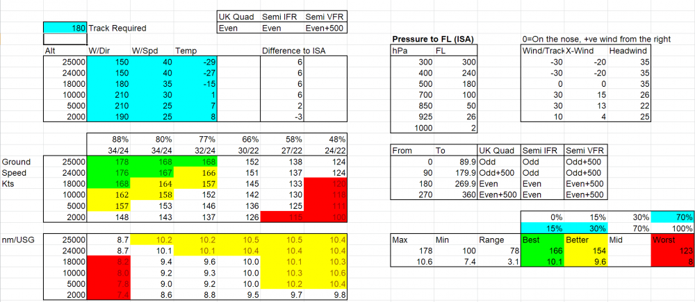
I already did this somewhere in times past: It's tailored for Bravo PoH figures and UK wind charts, but easily changed. It used Ed Williams aviation formulae, so has macros in it Put in the wind: (using SW UK in this example) and the desired track Read off the best/worst speeds and mpg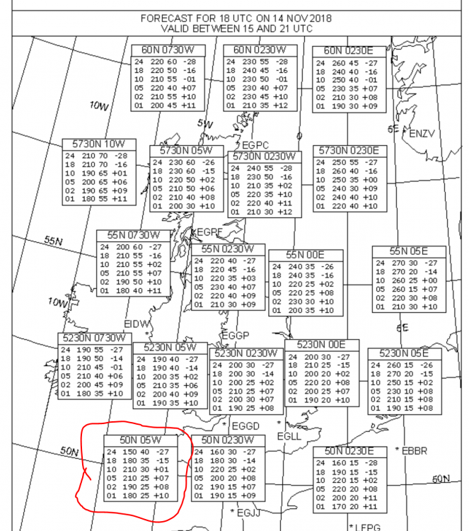
-
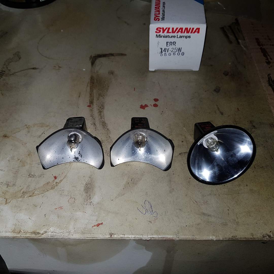
Ovation recog light replacment alternatives
Awful_Charlie replied to rogerl's topic in Modern Mooney Discussion
Finally dug out the bits and got round to taking some photos: From left: Bulb with sticker & leads removed, bulb with leads but sticker removed, bulb with sticker and lead removed, new uncut bulb with box behind ($3 from ebay) Two old bulbs and the new from the front - note that theold are trimmed off asymmetrically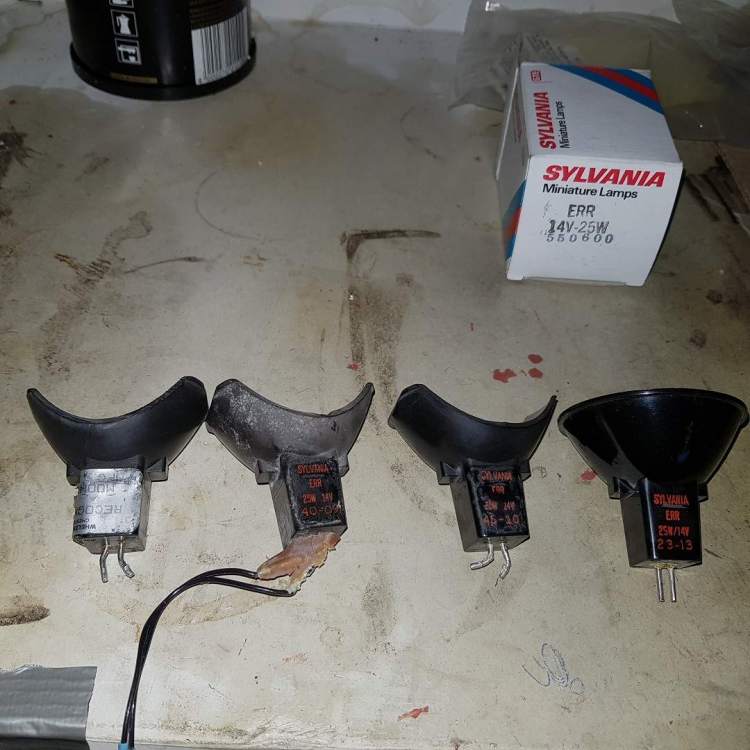

-
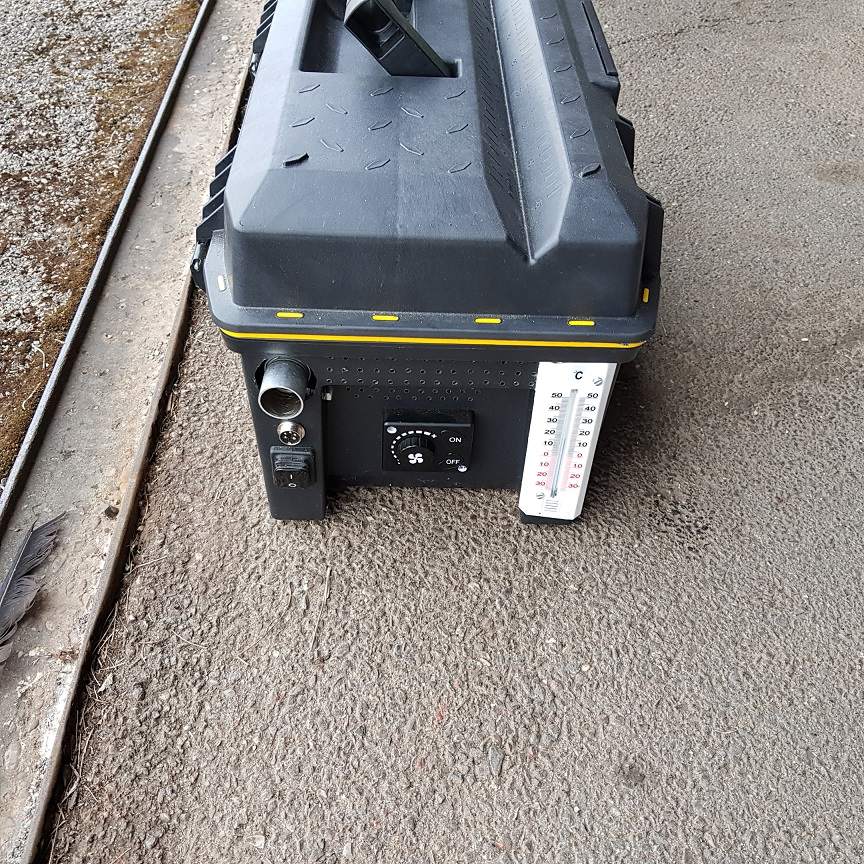
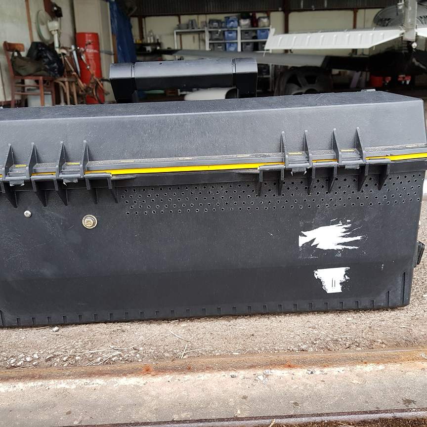
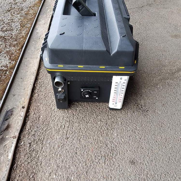
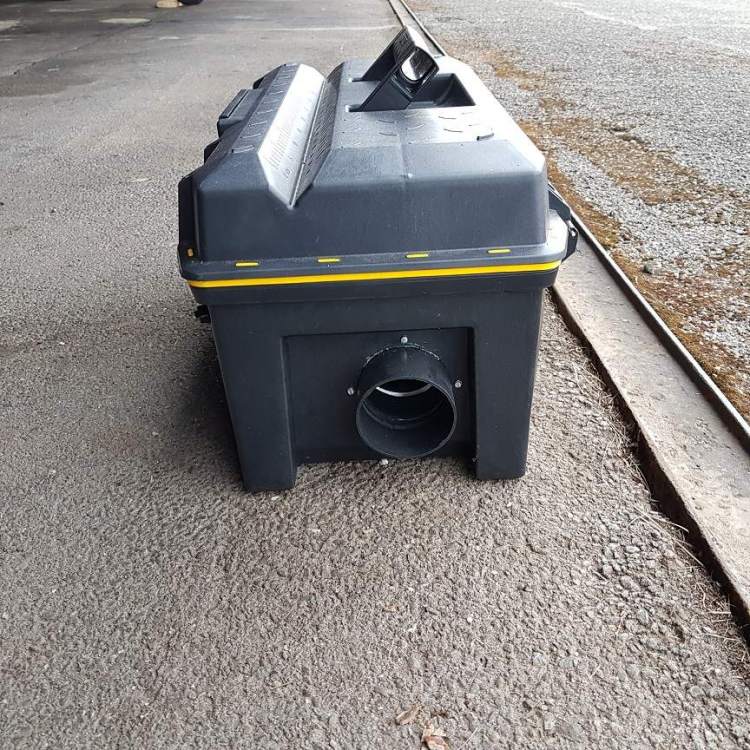
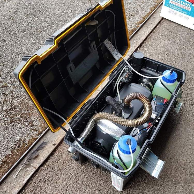
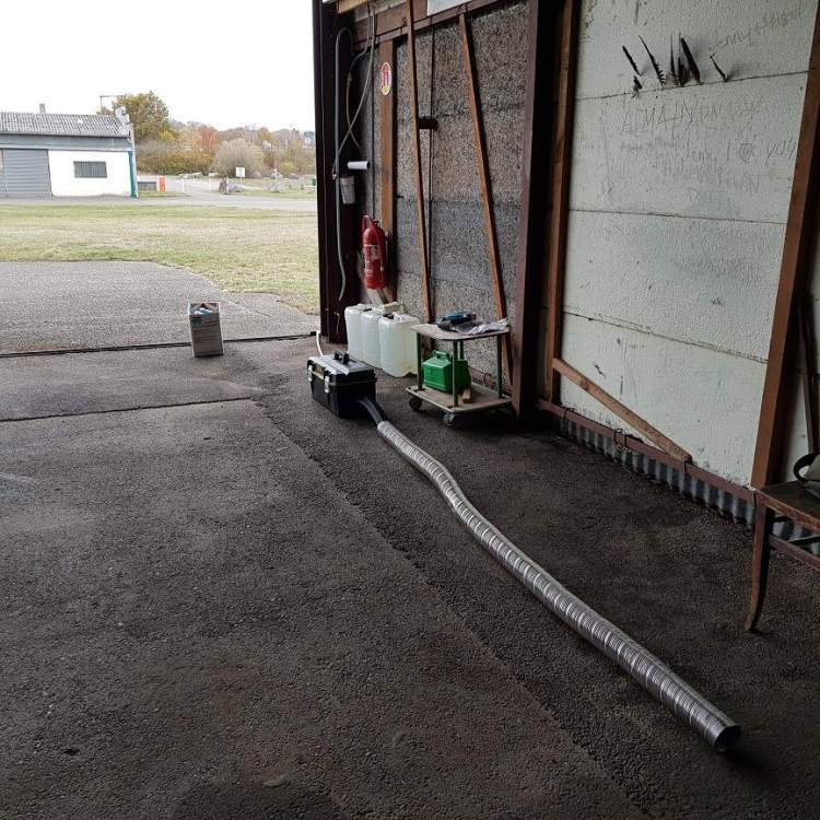
Thought I'd add to this, as thanks to the original idea, I went ahead on one of these. The only power I have at my home 'drome is via a generator, and I wanted something I could take with me too, as hangars for visitors can be quite difficult when touring. I also wanted something that could be used to eg heat a tent, or even potentially for working in the hangar. Things I wanted over Bob's original design were less protrusions on the exterior, able to be left as well as used outside (less susceptible to rain), and possibly a greater autonomy. If it could be more rodent-proof that would be an advantage, as would making it resistant to spills (I think the smell of diesel/jet fuel/heating oil in a confined space particularly nauseating) After getting the bits and starting to assemble, I wish I'd done more research before! In Europe, heaters like these are frequently found in boats and motorhomes, and sometimes the long distance trucks. They're often known by the trade name "Eberspacher" https://www.eberspacher.com/ where a D5 model equivalent from ebay could be had for less than USD250. The D5 uses up to 0.6 liters (a litre is near a dammit a quart) per hour foor a 5500W output After the heater itself, a tool box from a local DIY store (expensive - this is Switzerland!, but at least I could see what was inside etc before buying), fuel tanks, batteries, charger and some odds and ends from a model shop (batteries for an RC model were more like the load profile than a motorcycle battery I thought), and a couple of evenings with a drill and knife. Result: Fairly standard looking toolbox from a distance (Oil cans for scale!) On left, exhaust, charging socket and master switch, heater supplied control panel in the middle, thermometer stuck on the right Air inlet is via hundreds of small holes drilled below the drip line of the lid that continue round the tool box Hot air outlet All the gubbins: By routing the exhaust inside of the box I expect some slight additional heat recovery! Fuel tank vents to felt air filter incorporates a non-return valve, but hoping that the loops in the vent lines will prevent the stuff getting that far - has bee tested in the roll 90 degrees either way about the long dimension. No so visible is the aluminium plate between the heater and the batteries - the idea here is to get some heat to the batteries (after all, it is being used in the cold!) to improve the capacity With exhaust extension (just visible extending out of the hangar door - I expect to put a hole in the wall at a suitable position in due course) and duct extension (short black length is what will be used to go up the cowl flap for engine heating) for use in the hangar: Autonomy at minimum heat is in excess of 18 hours which is more than I needed. At maximum I'm expecting more than two hours, which should be more than enough for an engine pre-heat - maybe another report after the cold sets in (it has remained remarkably warm so far this autumn - maybe making a heater is going to give us a mild winter!!)


-
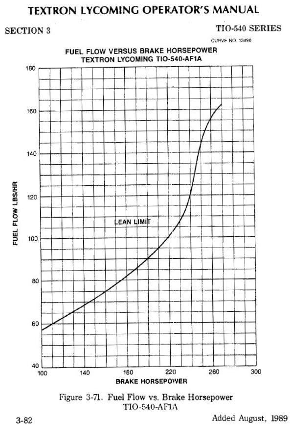
In addition to Dave's pieces, I'll try to add a bit: Let's have a quick look at torque and power before we get too far: Torque you are probably familiar with via the use of a torque wrench. Is is a measure of how hard you can turn something, and the typical example is one of a bucket in a well, where the drum on which the rope is would has a diameter, and the handle with which to wind also has a length. It doesn't matter about the diameter or the length of the handle for the amount of torque required to hold the bucket in one position, and to hold it stationary required no power, you have to apply so much force over a lever of a length which is why the unit is lb/ft or kg/m - like a see-saw used in the CofG calculations, you can apply half the force at double the distance for the same effect. If you want to move the bucket up, you need to exert not only torque, but maintain this over a period of time. So you could have a "low geared" well lift, where you wind the handle lots of times to move the bucket up one foot, or a "high geared" one when maybe only a fraction of a turn is required, but in the latter case you would need to apply a lot more torque. Power comes from multiplying the torque (which is already a product of the force and the lever length) and the rate of rotation, so consequently something at 0 RPM is making zero power, but back to the well, a tiny motor with very little torque but running through a reduction gearbox maybe able to lift the bucket - however a big motor at low RPM may have the torque to lift it without the gearbox. At the end of the day, if they lift the same weight bucket over the3 same distance in the same time, then they are making the same power. You can put a torque wrench in the vice and hang a few bags of sugar on it, and you can get a torque reading, but there's no power being produced! One way you can get power by burning fuel. You can burn fuel in a variety of ways, many of which are terribly inefficient, but if you want to extract more power (at a given efficiency) in a normal IC engine, there are two ways to do it: a) turn the engine faster (so it draws in more fuel and air) - as long as the torque doesn't diminish to much, as power=torque x more RPM ie more power (lift the bucket up faster) b) Ram more air and fuel in - this will (should!) give us more torque, so again power=more torque x RPM ie more power again (lift a heavier bucket up in the same time) Problem with a) is we need to keep the prop tips sub-supersonic (or the prop goes very inefficient) There's loads of reading out there on this too, but in summary, we need to keep the tips below about 0.85 mach or so. As the speed of sound is dependant on temperature (not air pressure!), then at high altitudes (in the cold), the speed of sound is lower, and a 75" dia prop (as we have on the Bravo), with a high TAS (which adds to the tip speed) we can get quite close even at 2400RPM. If you get up in the (very!) cold you can try this by setting max power at 2400, and then trying 2575 - if the tips get over the critical mach then you will actually slow down. (Obviously I hope, race/consumer engines for cars/bikes etc have different constraints) Problem with b) is you can only ram in so much with the compression before detonation comes a problem. The effective overall compression ratio is not that terrible, just some of the compression has taken place outside of the cylinder. A NA engine at FL180 only gets half the ambient sea level pressure, but a turbo'd one can get sea level or more, so that 10:1 ratio N/A is effectively 5:1 at FL180. In a turbo'd engine you can get the whole sea level pressure, but you're constrained by all sorts of other stuff such as the incoming charge temperature that it is principally the engine designers job to manage. With all that out of the way, we could over simplify things to say that if you burn fuel in the most efficient way possible (ie about 25-50 LOP) in an IC engine, for rotating shaft output, then the amount of power is dependant on how much fuel you lob in, hence the figures in Don's spreadsheet. Problem we have is primarily cooling and the speed of combustion, and to manage these the designer has specified an overly rich mixture at high power settings. This means we don't burn the fuel efficiently - we are putting extra in to cool the combustion and get a burn speed that allows us to get more power, albeit at an efficiency cost. Conversely, at low power, we are still making all the ancillaries and internals do their work, and these have an overhead (eg, take all the spark plugs out of your engine and spin it over by hand - hard work isn't it! Now spin it at 2400RPM and see how much power that needs!) That power is gone no matter how much fuel you put in. This is one of the factors the engine designer copes with for the idle speed - the engine might be making 10 or 20% of maximum rate power from the fuel ingested, but so much is used to internally before there is any to spare - if he makes the idle any slower, then there is not enough power to run the internal before we get anything useful for the prop, and hence the engine stops. The graph can be converted into BSFC (Brake Specific Fuel consumption), which is a measure of efficiency - how much power do you get from each pound of fuel. (Lots of reading out there on this too is you are interested) Really efficient engines (diesels) get down to maybe 0.35, gasoline engines rarely do better than 0.38, and even then only at a very controlled output. By converting the units in the graph we get a peak efficiency in the AF1A/B of about 0.45 or so which is pretty rubbish, but it is an abysmal 0.6 at max power, and over 0.5 below 50% power. The "sweet spot" for efficiency in that graph is thus in the 175-215BHP area, and outside of that it is starting to drop off Some of the good gas aero engines are getting to about 0.41 - 0.42 or so, only 0.04-0.03 difference, but this does represent 10% Hope that helps! Ben
-
JPI Oil Temperature Probe Question
Awful_Charlie replied to LANCECASPER's topic in Mooney Bravo Owners
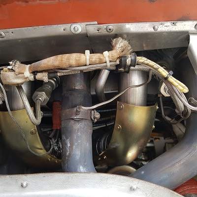
Mine is where you have re-located yours too - good job :-) Wire routes with the unconnected prop heater underneath the barrels to go through the firewall on the starboard side with the starter cable (and the rest of the JPI leads) Not a great picture - EGT and cylinder probes are on the stand-offs with the lower HT leads, Oli temp just visible at the back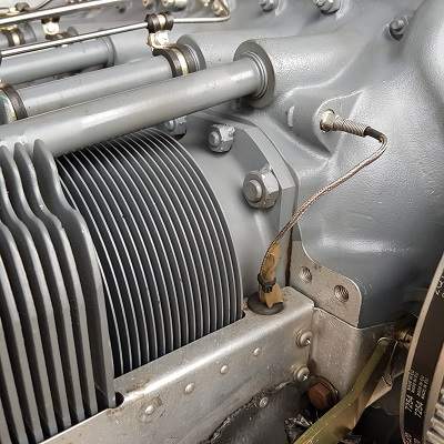
-
Note the limits from the fuel and Compression ration in Don's sheet above, but also read it in conjunction with the Lycoming PoH "Lean Limit" curve 13490: Note that when you get over 220BHP or so (75%) the BSFC is getting substantially worse - this is around the 16.5GPH. Unfortunately the Lycoming curve has nothing about the surrounding parameters, of which the likely most significant is RPM, so as they say, YMMV!

-
JPI Oil Temperature Probe Question
Awful_Charlie replied to LANCECASPER's topic in Mooney Bravo Owners
My oil temp probe for the JPI is installed as per the JPI manual - no problem with unbelievable readings (#3 CHT is unfortunately not the same - problem solving TBD) Why people decide to install probes in non-approved locations bewilders me - for instance this case was an expensive lesson! -
Altimeter vs manifold pressure gauge
Awful_Charlie replied to moontownMooney's topic in Avionics/Panel Discussion
RTFM!!! The JPI one! There's a table in there as it is *not* directly readable from the altimeter -
I'd go with Matt above, but one that no-one has added yet is tanks - whether it be bladders or re-seal, get them done before paint
-
Well, if it is any consolation Don, I sent my first run core back to Lycoming in June, so they most likely have one on the shelf!
-
Another good reason for LOP
-
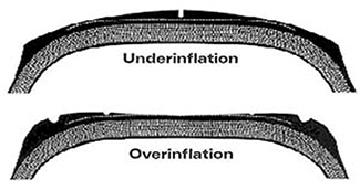
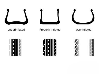
Classic under inflation wear Against the surface it does this: Results in wear like this:::
-
You could just send the unit back to JPI and get it upgraded https://www.jpinstruments.com/FAQCategory/upgrades/
-
I tend to fill to 8 and add at 7 - my last engine was getting tired and consumption got to about 1 quart after the first 10 hours, and then 1 quart after 5 hours just before oil change. That was with 4 original cylinders with 2200+ hours on them. New engine is just about run in now, but a few leaks have distorted the recent figures, so will hopefully get a better trend after the next (imminent) oil change has done the hours. Remember that zero or very low consumption is not necessarily a good thing - check Lie #5
-
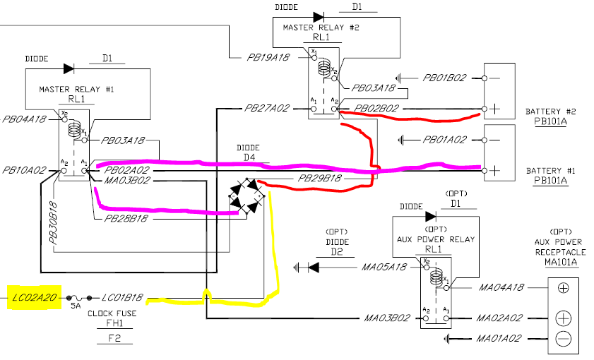
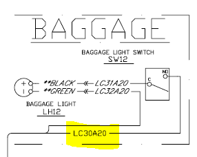
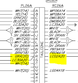
Maybe a good time to remind owners to check their wiring diagram.... For a long time, there have been posts about those who left a baggage light on to return to a flat battery. I had smugly assumed that dual batteries would still leave you one to start with, but it is not necessarily so! Bravos 27-0232 to 27-0239 (and probably others) have a supply with rectifier bridge that *only* feeds the clock in the panel and the baggage light (and also the panel/glareshield dimmer control, but this is isolated with the master) - the net result that either of these circuits have the possibility to drain *both* batteries. Fortunately someone had observed the light on overnight and left a message with the tower, and they contacted me first thing in the morning, which gave me the chance to get a maintenance shop to remove, recharge and refit both the batteries before a late afternoon flight
-
Brand new Bravo owner with Monroy fuel question
Awful_Charlie replied to Knuckledragger00's topic in Mooney Bravo Owners
I got mine weighed before I bought it, and yours does sure look a bit heavy - do you have AC as well? FWIW, mine is 2384 BEW, but the arm is a less convenient 43.27 despite having 12lbs (2 units) of charlies in the tail, so for me I'm more often limited by forward CofG limit. They weighed it with a nearly full load of TKS fluid too, so I had to calculate it back to get a 'proper' figure Don't forget you can remove the rear seats - for me this gets 35lbs back. For fuel, (I have the LRT too), just below the bottom of the standpipes ("Full" in the chart below) will be around 100 USG - I made the table up by running a tank dry and the filling it slowly and taking the pump readings at several points. I've done this on several different occasions for each tank and averaged them out - I suggest you do this yourself in due course to get the figures that suit your aircraft! (we buy in litres over here, hence the extra columns). The difference in unusable by POH and unusable in straight and level flight for me is near as dammit to 2USG - you'll have to decide on what you use as a reference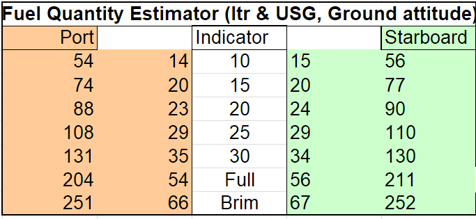
-
I'll just toss this in here, as it might help others going through engine replacement or planning thereof Factory reman, installed in May this year, running in ok, but started to drip oil after about 25 hours. Cause: The cylinder head drain tubes, where the aluminium tubes goes into the rubber tube on the sump were insufficiently tightened. Cure: Tighten the hose clips More leaks after 40 hours or so. Cause: Cylinder head oil injector to cylinder head. Cure: the injectors all took nearly a flat (1/6 turn) to nip them up again Suggestion: a) Before installing the engine, arrange hose clips on cylinder drains to give best possible access after installation and verify tension b) Check cylinder head oil injector torque at installation, and re-check at subsequent oil changes until stable
-
When to overhaul the turbocharger?
Awful_Charlie replied to Rick Junkin's topic in Mooney Bravo Owners
Friend who runs a Lycoming powered Malibu reckons on changing turbos at 1000 hours (in line with Don's recommendation), although in that application they have a harder time due to cabin pressurisation. A previous owner of my aircraft got through a number of turbos in short succession, at least one due to ice damage. The last one made a bit over 1000 hours before I had to change it due to a collapsed bearing -
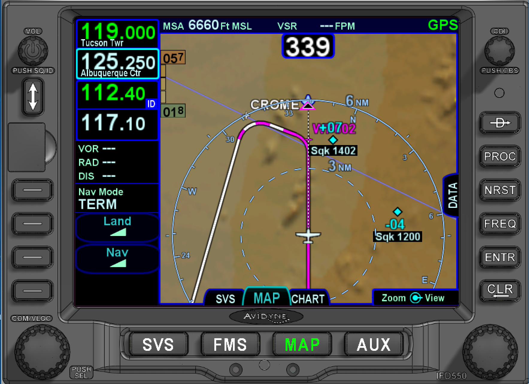
If the FD is only demanding a half standard rate turn then it suggests the servo is responding correctly. However, if the AP will not turn enough in any mode, I think this needs to be addressed, as it is not turning enough even in heading mode then my feeling is you are on a bit of a losing battle (unless you fly very slowly!). Have you tried resetting the Aspen GPSS gain to standard? I have a feeling the values in that are "inverted" (eg GPSS=2 means half rate, and GPSS=0.5 is double), but in any case setting standard can remove that unknown I don't know the S-TEC, but some more modern autopilots have the GPSS built into them, and if this is the case then the Aspen GPSS is out of the loop In a flight plan route, ALL waypoints/intersections/VORs/NDBs etc are fly by. You can't demand code a fly-over in a route, that is the sole domain of Jepp (as the Navdata provider) in a procedure I ran the route through the PC sim (SW 10.2.0) and got the same result. I tried creating a user waypoint at the same position as CROME and using that made no difference. By adding a waypoint before CROME to reduce the turn it behaved as I would expect: Notice how these are both now displayed as fly-by. I'd have to go flying to see how mine behaves with a very acute turn as in this case, but I would expect it to do as Marauder shows above

-
Not that it's going to be much consolation to you I'm afraid, but with IFD540, Aspen PFD1000 and KFC150 I don't get this problem, even with turns >120 deg. Hate to ask you to suck eggs, but you are running with GPSS enabled, and not just via NAV? The turning behaviour could be explained at a stretch perhaps if you were in NAV mode (on my installation this would mean autopilot in HDG mode and GPSS indicated on the Aspen) Will the S-TEC do rate 1 turns (or very nearly) with the heading bug or in NAV mode? If not it might point towards servo limit switches of rigging tensions (I know nothing about the S-TEC installation), if it does than maybe you can up the GPSS gain in the Aspen? (but where is the S-TEC getting the GPSS from? Aspen or direct from the IFD?) Do you have a flight director, and if so, does that show a demand for more bank in the turns than the autopilot executes? It does seem rather odd that your flight plan shows the immediate turns - normally all waypoints in the flight plan are "fly by" unless they are coded by Jepp as "fly over" as part of a procedure, did you have anything "odd" in the flight plan (eg intercept a radial). You could try this in the simulator to see what that does, and either way feed it back to Avidyne (on their forum, or to tech support - I've generally found them responsive on both)
-
No, if you want to know the temperature coming out of the intercooler, you should add the IAT (Induction Air Temperature). This will be another probe between the intercooler and fuel injector assembly - on a JPI it is just another probe, maybe like the EGT probes but other styles are available. I used a https://www.jpinstruments.com/shop/tit-716-20-screw-type-probe/ as this screwed into an existing boss on my induction system
-
Mooney performance charts in XL
Awful_Charlie replied to patrickf's topic in Modern Mooney Discussion
That is brilliant Patrick - well done! Please check your PMs - I want to copy this for a Bravo -
Avionics Upgrade - Antenna Questions
Awful_Charlie replied to Reid's topic in Avionics/Panel Discussion
I'd suggest you get your Avioncs tech on the case - each antenna has its own location/seperation requirements, and some antennas have approved mounting positions on each airframe type. In most cases, these are "for best performance" but in others it is a mandatory requirement. In addition, each transmitter/receiver will likely have a list of approved antennas, and using something not on that list will involve extra pain. It will certainly help the tech if you can tell them what equipment you want to retain and what can be removed, and probably a good idea to discuss with them future plans for additional equipment -
Icing conditions climb and descent
Awful_Charlie replied to milotron's topic in Modern Mooney Discussion
I use the speeds and techniques specified in the AFMS