All Activity
- Past hour
-

Rocket in landing incident at KHND.
bluehighwayflyer replied to NickG's topic in Mooney Safety & Accident Discussion
No telling. But agreed. If fencing, a gate, perhaps? Whatever it was, it didn’t fare any better than the Rocket did. -
I think you are asking for people not to provide shop recommendations but only provide time and price?
-

Rocket in landing incident at KHND.
kortopates replied to NickG's topic in Mooney Safety & Accident Discussion
I was thinking part of a lighting system too, ALS, runway light, taxiway light … ? But who knows? Sent from my iPhone using Tapatalk -
I’m pretty close to you right now. I’m at KJFX.
-
I'm heading down to San Diego from No. Cal. at the end of next week w/ first time flyers, and wish to make it as smooth and glitch free as possible Either KMYF or KSEE appear to work equally well. Would one be better than the other to land , TO and tie down for a couple days. Any tips or suggestions for the airports. Thanks in advance for any advice / experiences Roger
-
It is almost always the field wires. Check that first.
-
Hank- I could fly up and give you a ride back home if you want. I need to fly.
-
Hey, guys. Neither the Hi Volts nor Low Volts lights came on, and the Ammeter was centered. But 10 miles south of KSYI, the GPS reser itself twice, and keying the mic on Com2 also reset it. So I squawked 7600, hand cranked the gear down and eased her to the runway. While I was orbiting nearby and cranking, the transponder readout went dark. I'm guessing alternator failure. Turning the prop a bit to check the belt (tight) seemed to have more resistance than normal, which also makes me think the alternator is shot. Wonder why the lights didn't come on? Anyway, it's a holiday weekend, and Enterprise was nice enough to rent me a car home. When I return the airport courtesy car, I'll ask about a local A&P. Any preferences in this area? All recommendations gladly accepted. Its a 4 hour drive home, not too bad for a 1:12 flight up. Thanks, ya'll!
-

Did Mooney survive the flooding in Kerryville
Matthew P replied to Matthew P's topic in Vintage Mooneys (pre-J models)
Thanks -
+1 on Bruce Taylor at Air Power Accessories. He is very experienced with the dual mags, and talked me out of doing an overhaul and just doing a 500-hour for some good reasons. Mine was done in February for about $1800 and it's been fine. Bruce is very good to work with. Highly recommend.
-

Rocket in landing incident at KHND.
0TreeLemur replied to NickG's topic in Mooney Safety & Accident Discussion
If that's part of a fence then it is a weird fence. Fences don't usually have black painted metal ribs and short white cylinders. Could it be part of an Instrument Landing System antenna? -

Did Mooney survive the flooding in Kerryville
Paul Thomas replied to Matthew P's topic in Vintage Mooneys (pre-J models)
The factory is fine per Frank Crawford. - Today
-

Did Mooney survive the flooding in Kerryville
bonal replied to Matthew P's topic in Vintage Mooneys (pre-J models)
Watching this on the news way to tragic praying for all involved. -
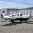
Aging airplane and systems: What would you do?
bonal replied to Immelman's topic in Vintage Mooneys (pre-J models)
Dogs rule, love that picture -
Rocket in landing incident at KHND.
bonal replied to NickG's topic in Mooney Safety & Accident Discussion
Because it’s easier to say, amazing that there were no serious injuries considering the amount of force to do that kind of damage. -
Work is getting in the way. My wife won't be able to make it and it's not looking good for me either but I'm hoping to shift some things and make it later in the week. Have fun!
-

Did Mooney survive the flooding in Kerryville
TangoTango replied to Matthew P's topic in Vintage Mooneys (pre-J models)
According to the FEMA Flood Map,165 Al Mooney Rd appears to be outside the mapped flood plain. The map at the link drops the address pin in the wrong place; Mooney's buildings are the white roofs just west of the runway 3 threshold. -
MT Propeller bragged about this too, but it turns out that their props are infinitely repairable as long as you bring infinite amounts of money to completely replace anything that might look like it is thinking of wearing out. Aerodon
-

Can you replace a KX-155 with a KX-165?
Aerodon replied to MikeOH's topic in Avionics/Panel Discussion
I think you are referring to the 'radial indicator' feature. The KX 155 needs an indicator like a KI209 that has the internal decoder. The KX165 has this decoder in the radio, and needs an indicator like a KI206. Last time I looked, I think you can slide a KX165 into a 155 position and it will work. But not the other way around. Aerodon -
Do they fit in our wings? I saw a retrofit (a K - don't we all have the same wing?) and the speed brakes were sticking out of the wing and there was some gaudy plate that covered them.
-
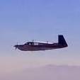
Did Mooney survive the flooding in Kerryville
47U replied to Matthew P's topic in Vintage Mooneys (pre-J models)
Very dramatic, tragic loss of life. I took this on an SWA flight into SAT. The river runs just south of KERV, but there is some elevation of the airport above the river flood plain. I’ve landed at ERV a couple times and I don’t remember that the proximity of the river was obvious from the ramp.
-
Rocket in landing incident at KHND.
47U replied to NickG's topic in Mooney Safety & Accident Discussion
Perhaps not purposefully designed with the intent to provide roll protection (who knows what Al was thinking at the time), certainly the attributes of the steel tube fuselage structure results in providing protection to occupants in the unfortunate circumstance that aircraft ends goes inverted. Or penetrates trees or other obstacles on the way down. Like a roll cage. I don’t know what else they ‘get’ incorrect, but can’t you give them a pass on this one?

-
Did Mooney survive the flooding in Kerryville
Matthew P replied to Matthew P's topic in Vintage Mooneys (pre-J models)
I saw on the news that showed a picture of downtown Kerryville -
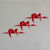
Rocket in landing incident at KHND.
bluehighwayflyer replied to NickG's topic in Mooney Safety & Accident Discussion
Presumably some of the steel fencing. -

Rocket in landing incident at KHND.
exM20K replied to NickG's topic in Mooney Safety & Accident Discussion
What is this?