Vance Harral
-
Posts
1,550 -
Joined
-
Last visited
-
Days Won
6
Content Type
Profiles
Forums
Blogs
Gallery
Downloads
Events
Store
Everything posted by Vance Harral
-

mats for protecting wing finish during fueling.
Vance Harral replied to Vance Harral's topic in General Mooney Talk
That's a kind offer, Paul, and a good excuse to get together. How 'bout you evaluate them and post a PIREP here? I'll buy the spare from you - and lunch - if it goes well. If it doesn't, I'll fund a follow-on experiment and give you one of whatever we try next. -
mats for protecting wing finish during fueling.
Vance Harral replied to Vance Harral's topic in General Mooney Talk
This is an interesting question. The fueling mats for sale at Spruce are made of polyurethane. My understanding is the electrical properties of silicone and polyurethane are similar. I think the silicone baking mats we're discussing here are probably "fine" vs. purpose-designed choices in terms of risk. But now that I think about it... regardless of the material used, I'm thinking you probably want to ground the airplane before laying down the mat, and (perhaps more importantly) remove the mats before you disconnect the ground. That would seem to be the lowest-risk procedure. -
mats for protecting wing finish during fueling.
Vance Harral replied to Vance Harral's topic in General Mooney Talk
Silicone baking mats sound like a great idea. Thinking something like this would fit the bill with a DIY hole cut out: https://www.amazon.com/gasare-Silicone-Countertop-Protection-Resistant/dp/B07K6YZY21 -
Mr Miyagi was on to something....
Vance Harral replied to GDGR's topic in Vintage Mooneys (pre-J models)
Even an old workhorse with bad paint shines up pretty decent with basic products from the auto parts store. All it cost me was a few bucks and a lifetime supply of ibuprofen for my sore shoulders and forearms. Haven't flown it yet, will hope for good results like GLGA!

-
Just finished a multi-day job of polishing up the airplane. It'll always be a workhorse rather than a beauty queen, but polish and wax still make a difference. One of the high-elbow-grease parts of the job was polishing all the marks and scratches around the fuel caps from the fuel nozzle, and from laying the caps themselves on the wing. I'm thinking about carrying a fueling mat in the future to reduce this. Ideally something small and lightweight - just big enough to shield the tank opening a few inches on all sides, with enough spare room to set the cap on. Spruce has some fueling mats, but the high-end model is expensive and seems designed for commercial use; and the low-end model gets poor reviews. Both look heavy. I've seen much smaller/thinner mats that look more appropriate for personal use, but after searching for them online to no avail, I'm thinking they were probably DIY jobs. For those of you that use fueling mats, any suggestions?
-
Partial panel/loss of control in IMC
Vance Harral replied to BorealOne's topic in Mooney Safety & Accident Discussion
I understand now that you and I are talking about two different things. You are talking about not losing gross control of the aircraft: getting upside down, ripping the wings off, etc. I agree almost any "low end" backup attitude indicator is helpful in reducing that risk, including the imprecise AHRS in the GTX-345. I also agree the risk of complete loss of control is reduced at slower speeds. But I'm talking about executing an instrument approach to minimums, well enough not to get off course resulting in CFIT, even though the airplane is still flying at normal attitudes. My odds of being able to do that traditional partial panel were "decent" because I practiced it... at least until a recent 2+ month hiatus due to the combination of a complicated annual and the COVID pandemic. But even at my most proficient, there has always been room for improvement in my partial panel skills. Accordingly, I chose not to fly my airplane over widespread low IMC. I was considering changing that strategy after installing a GTX-345, with the rationale that I now have attitude backup if my vacuum AI rolls over and dies. Based on what I've seen actually flying with the iPad and GTX-345 though, I've flipped back to my original mindset. I reserve the right to adjust my risk profile yet again with further practice, but I'm not there today. Having said all that, my original point stands: I've met pilots who changed their risk management profile based on having backup attitude information they have not actually practiced with. That's a sketchy idea even with a high-end, certified attitude backup solution. It's an even worse idea with a portable, uncertified solution. Go practice with your backup, then adjust your risk management profile based on your experience. Make the decision based on real flying, not armchair flying. -
Brittain Servos help
Vance Harral replied to CanyonMedical's topic in Vintage Mooneys (pre-J models)
Has anyone called Brittain lately? I'm not sure of their "hibernation" status. Right after Jerry died, we called Brittain and ordered a set of the rubber boots to stock in our own personal inventory against future ruptures, though we haven't used any of them in anger yet. It was some of the very last stock of boots, I think. I thereafter read reports of Cecelia telling other callers she had no common parts in stock, and that she was simply trying to keep the company alive until a new investor could be found. One assumes that if a new investor is able to resurrect Brittain as a going concern, manufacturing new boots and getting back into the servo overhaul business would be their first priority. As for "finding some servos only a few years old", I don't think anyone has manufactured completely new Brittain servos in decades. The best you can get is new boots/seals/tape on old cans; but that's OK as the cans are essentially indestructible. There was a time when Brittain would ship an overhaul kit to the field with boots and seals; but in latter years the FAA got on their case and required them to have customers send servos to the factory for overhaul. You can let your conscience be your guide on what that means when the manufacturer is no longer able to provide the service. I consider it to be an "owner produced part". -
Partial panel/loss of control in IMC
Vance Harral replied to BorealOne's topic in Mooney Safety & Accident Discussion
The problems I described with my experiment using the iPad as an emergency backup occurred while flying level approach at 90 knots. I disagree with the suggestion they can be alleviated by slowing down. Or, if they do vary with speed, I actually think you have it backward: I think they're less of an issue in cruise than they are on an approach. Let me elaborate on a couple of things. First, it's not that I had trouble keeping the aircraft upright or that I was ever anywhere close to an unusual attitude. Rather, the errors and lag in the displayed attitude resulted in my chasing heading/track and altitude excursions. e.g. I'd set a straight and level attitude on the display, but see track and/or altitude slowly changing. So I'd input a small bank and/or pitch correction to fix that - which might or might not be immediately reflected in the attitude display. Then I'd try to re-frame my brain, like "to hold a constant heading, I think the display needs to show a 2-degree left bank"; only to discover the error didn't seem to be consistent. The net result was that my performance wasn't really any better with the backup iPad attitude display than with traditional partial panel technique. I mostly blame this on the GTX-345 AHRS that generates the attitude information. I've seen several reports that it's simply not a high-quality attitude reference, and my own experience agrees: OK for emergency backup, but just not accurate enough for the single-digit bank angles and half-bar pitch changes associated with precision instrument flying. My guess is most of the AHRSs people are thinking of as emergency backups are similar: Stratus 2/3, Sentry, GDL 52, etc. I freely admit I only have experience with the GTX-345. But my technical reading on the matter leads me to believe there's a good reason why certifies AHRS systems are expensive, and inexpensive AHRS systems aren't certified. The second issue for me wasn't a problem with the hardware/software, but rather a lack of experience with high-end, digital attitude depiction. I have essentially no time behind a G1000, Aspen Evolution, etc; and therefore no experience with synthetic vision depictions. By default, the Foreflight attitude display is backed by synthetic vision information: it includes both terrain depictions, and augmented-reality pointers that show nearby airports. What I didn't appreciate until I tried it is that if you hold a fixed pitch/roll attitude on this sort of display, the depiction changes even though your attitude is not changing. Perhaps this is intuitively obvious in a turn. But even when flying straight and level, terrain and airport pointers slowly slide down and to the side of the display as your position moves forward. Not being distracted by this requires an adjustment in thinking, even on a huge display with an infinite pixel count and frame rate. On a small display with limited pixel count and limited refresh rate, it's even more distracting to a pilot used to looking at an old iron gyro, or even a digital presentation with a simple sky/ground background depiction. I have no doubt I can get used to this, and I'll continue working on it. But it's another great example of how a very nice tool can get a pilot in trouble if they're trying to use it for the first time in a high stress situation. -
Partial panel/loss of control in IMC
Vance Harral replied to BorealOne's topic in Mooney Safety & Accident Discussion
Strongly suggest those of you relying on an iPad for emergency attitude information cover up your traditional instruments and actually spend some time flying with it during training. I'm sure some of you have, but for those that haven't... when I gave it a shot, I found it surprisingly difficult. Partly this is due to the AHARS built in to our GTX-345, which turns out to be marginally OK for keeping the greasy side down, but rather poor for precision control (frequently shows a slight bank when straight and level, and lags actual attitude just enough to make fine control difficult). Partly this is due to the Foreflight display, which I found distracting and "swimmy" for various reasons that are probably just personal. The point here is not to say it can't be done, it most certainly can. But it's just different enough that I sure wouldn't want to be trying it for the first time in an actual failure scenario. My casual poll of a locals who are excited about the emergency backup capability of their iPad suggest about half of them have never actually used it in real or even simulated IMC. Like any other tool, it shouldn't be relied on unless you've trained with it. -
What the heck happened to my gascolator?
Vance Harral replied to cferr59's topic in Vintage Mooneys (pre-J models)
The part number I quoted is what was shipped to us for our 1976 M20F with the Duke's selector, by LASAR a couple of months ago. I believe it's the same selector used in your aircraft, but it's possible I'm wrong. To be honest, the screen wasn't an absolutely perfect fit for us - the inner "doughnut hole" was a little on the small side and had to be slightly stretched around the center port of the selector. I don't know what the difference is between the P/N I quoted and the one you found on LASAR's site, or if that has anything to do with the fit. In any case, strongly suggest you just call the LASAR parts department Monday morning and chat with them. This is the kind of thing where you're going to get a lot better answer from a human on the phone than from browsing a web site. Your order wouldn't ship until Monday if you placed it on the web this weekend, so there's no reason not to call. As for the screen itself, I wouldn't say the edges of it are "sharp". But they're just cut out of a mesh screen material, they don't have any kind of refined edge that keeps them from fraying if mis-handled. I do have a hard time believing your screen shredded your gasket through pinching and/or vibration, though. The screen material just isn't that robust, and the assembly shouldn't result in the screen grinding hard on the gasket anyway. It looks more to me like the rubber gasket just got brittle and crumbled over a long period of use without replacement. Just a guess on my part, I'm not an A&P and don't have that much experience working on selectors. I have zero experience with the gaskets from Brown mentioned by MB65E, but it's likely they're fine. Uou're not going to get that Mooney-specific P/N gasket from Mooney themselves anyway, at least not at the moment. My airplane partner has been trying to get a hold of them all week, and they are returning neither phone calls nor e-mail. So the choices are LASAR or other MSC, or Brown. -
What the heck happened to my gascolator?
Vance Harral replied to cferr59's topic in Vintage Mooneys (pre-J models)
The large gasket is Mooney P/N 940057-001, it's about $50 if you actually purchase the OEM part. No idea why it's so expensive other than being a Mooney-specific P/N. The stat-o-seal washer (that goes on the bolt that attaches the bowl to the rest of the selector) is P/N 600-0101-10, couple of bucks. The screen is P/N 10543-1, about $10. LASAR has all these parts in stock, or at least they did when I ordered them a couple of months ago. Be very careful reassembling the bowl. If it drips fuel on reassembly, don't try to fix it by torquing the bolt past the 15 in-lb limit MB65E mentions. Doing so can break the fuel selector, and parts are very hard to find. Ask me how I know. -
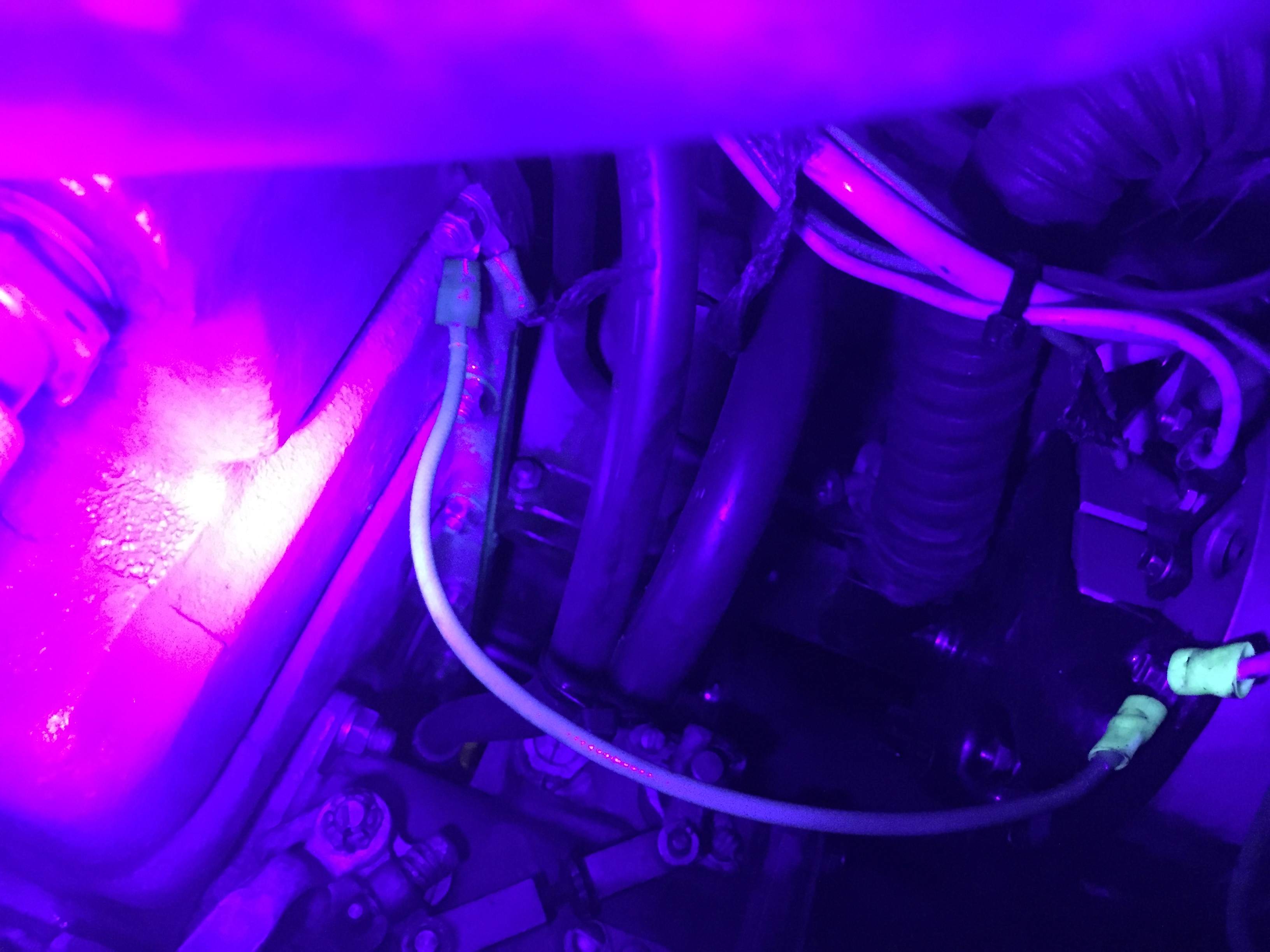
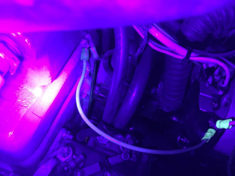
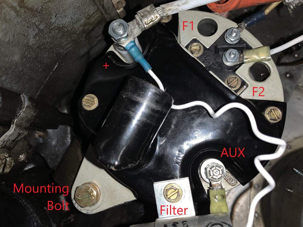
The shielding for the field and output wires just have to be grounded somehow to minimize electrical noise, that requirement is independent of the internal alternator circuitry having a ground connection. The schematic I posted above shows the shields being connected to the field terminal that is grounded to achieve this, and that's the gold standard because it minimizes the length of wire that is unshielded. But on my particular alternator the field terminals are in kind of a tight space, and I think grounding the shields there just "isn't done that way". In practice, any nearby good ground is OK. If you look at the picture of Maurader's alternator below, you can see where the shield for one of the field wires has been attached to a screw that holds the cooling shroud on. That's an "OK" ground, because the case of the alternator is grounded as discussed previously, and the cooling shroud screw goes into the case. But it's not a "great" ground because the cooling shroud itself is plastic, so the only ground contact mechanism is the screw threads. That may be the reason there is another ring terminal on that screw. In this picture the wire for this second terminal has been cut. But at one point it may have been wired to a better ground connection somewhere, to better ground the shield.
-
The field wire to F1 should just be replaced entirely, it's obviously quite old. The other's don't look too bad to me in person, but I appreciate the caution. The output terminal does have a boot, it's just pushed out of the way for the photo. You can see part of it at the upper right of the picture. Putting a boot on F1 makes sense, that's the output to the field terminal from the regulator. I'll take that into consideration when the associated wire is replaced. The wire on F2 just goes to ground, I don't think it needs a boot.
-
The lack of a separate ground terminal indicates the (-) node of the circuit is internally connected to the metal alternator case. Because the case is mounted to the airframe, the mounting bolts effectively serve as the ground connection. Most automotive alternators work this way. Here's a typical image, note the ground connection being shown as the case:
-
To close up the thread: got out to the hangar today as planned. Disconnected the ground wire from the AUX terminal, and alternator is now working as designed. The ground wire that was connected to the AUX terminal shares a ground connection with the shielding cable for the primary lead. So the wire needs to be grounded, but not the aux terminal of the alternator. Thanks to all who offered help in this thread, I appreciate it.
-
That's a good point about the witness marks around the mounting bolt. But it would be unusual to put an electrical ring terminal around a truly structural mounting bolt. And while it's tough to tell from the UV blacklight photo I posted above, I don't think I see any wiring going to the mounting bolt. My plan today is to head out to the airport, disconnect the wire from the AUX terminal, and try a ground run. If that resolves the problem, I'll have the A&P come take a look too.
-
Should be, but isn't. If anyone actually has a manual for the Hartzell/Prestolite ALY-8520, let me know. Absent that, other Hartzell alternator manuals are the only reasonable source. I am a professional electrical engineer, working directly with a professional A&P. Short of trucking the entire airplane with the alternator in situ to the Hartzell/Prestolite/Kelly Aerospace/Whoever-owns-the-rights-this-year factory, this is as good as it gets.
-
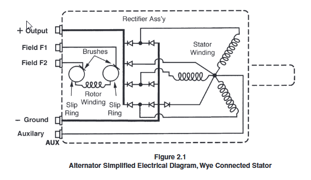
The schematic below is from a different set of Hartzell alternators, not the ALY-8250. But if the ALY-8250 is wired the same way, I don't think grounding the AUX output can actually damage any diodes. The center of the stator wye varies between output and ground voltage during normal operation (averaging about half the output voltage), regulated by the two diodes between it and the output/ground terminals; so it appears to be "normal" for it to be at ground potential at least part of the time. I think all grounding the aux terminal does is reduce the EMF that can be generated in any of the stator coils. In that configuration, I think the alternator could still produce rated output if the field current was high enough. But my guess is the max field current the voltage regulator can produce is insufficient to produce rated output when the aux terminal is shorted to ground (as opposed to connected through a charge warning lamp or other nonzero load). Of course, I could be wrong. Electrical machines were never my forte, I'm a digital guy at heart.
-
The plot thickens... Below are two photos of good installations: one from Marauder that I don't think he'll mind if I share, and another I took when I was trying to chase an oil leak a couple years ago. Both photos show the AUX terminal not connected to anything. Both photos show the brass cooling shroud screw between the F1/F2 terminals and the AUX terminal being connected to a ground wire, which in our case I think goes to the negative terminal of the landing light. I don't actually think the purpose of the wire connected to the cooling shroud screw is to ground the alternator frame. I think it's just a convenient place to tie something to ground. My guess is the "main" ground of the alternator frame is the mounting bolt. That said, in Maurader's photo, one of the things connected to the cooling shroud screw is clearly a grounding strap, and in my photo the cooling shroud screw is clearly connected to the oil pan.
-
OK folks, here's a picture of the back of my alternator, with connections labeled. I found several things of interest: There is no large terminal on the back of the alternator actually labeled GROUND(-), which is surprising to me. The large terminal the bottom of the picture labeled AUX has been wired to the engine case. If this was not supposed to be grounded, I can forgive my mechanic for an honest mistake, because with no terminal actually labeled GROUND (-), the AUX terminal sure seems like the one to connect to ground. The nut holding the ring terminal of the grounding wire to the AUX terminal of the alternator was loose. So even though the mechanic intended to ground this terminal, it was probably making a marginal ground contact at best. I don't have a manual for the ALY-8250, but I found another Hartzell alternator manual online that covers several models, and the diagrams for all of them have a really big, obvious GROUND terminal separate from the AUX terminal. The ALY-8520 does not. What deepens the mystery is that in the pics Maurader sent me of his ALY-8520, one of the small brass screws that holds the black plastic cooling shroud on the back of the alternator has a ring terminal attached to it. Not sure what that would be for, except maybe to ground the case of the alternator to the airframe or engine (perhaps that's the missing ground connection in my installation!). But if the GROUND connection on a Hartzell ALY-8520 is just the case of the alternator itself, I'd think the mounting bolts would provide sufficiently good ground. Comments?
-
Marauder, your pictures are very helpful. Thanks for taking the time to respond!
-
Actually headed out to the hangar later today. Appreciate all the schematics. Anyone happen to have pictures of an actual installation?
-
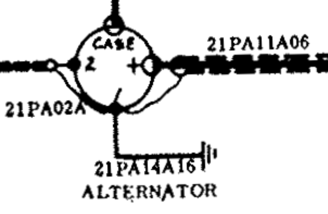
The bottom of the circle that represents the alternator has a terminal dot labeled "1", which I take to mean "F1" of the Hartzell ALY-8520. See slightly higher-res picture below. The shields from the "+" and "2" wires do connect to the "1" terminal, but it seems clear to me that terminal "1" is itself grounded, and the shields are just conveniently connected there. One thing that makes this obvious is terminal "1" obviously can't be left floating. If it's not supposed to be connected to ground, what else would it be connected to? The only leads emanating from that terminal are the wire shields and the ground connection.
-
The factory schematics for my aircraft show the F1 terminal grounded, see attached screenshot. Current needs to pass from F1 to F2 for the alternator to work, but there is nothing wrong with one of those terminals being grounded. I'd bet that installations which connect both F1 and F2 to the regulator likely have one of the connections internally grounded inside the regulator.

-
Trying to debug an alternator problem and would appreciate some pics. Aircraft is a 1976 M20F with a Hartzell ALY-8520 alternator. Alternator was removed during our recent annual and sent to a repair shop for IRAN, due to significant electrical noise that did not seem to be caused by loose connections. The alternator shop reported they "found a broken wire" internally, and that the alternator was full of grime (mostly oil leaked from the motor). Broken wire was supposedly fixed and everything cleaned, but I do not know if the re-assembled alternator was actually bench tested. In this time of social distancing, I also was not able to participate in or observe the alternator being re-installed in the aircraft. The mechanic that did the work completed the annual taxied the airplane back to our hangar a couple of days ago, and unfortunately reports that the re-installed alternator does not appear to be working at all: he saw a discharge on the ammeter and a flashing voltage light from the voltage warning system. He has offered to work with us to resolve the problem, but the airplane is no longer in his shop, it's back in our hangar. One possibility is that the IRAN shop botched the job and broke our alternator, but I'm hoping it's just a simple wiring error committed on the re-installation. I'm headed to our hangar tomorrow with flashlights, mirrors, and a voltmeter to take a look. I don't actually have an installation manual for the ALY-8520, but based on manuals for similar alternators, the schematics for my airplane, and a rudimentary understanding of principles, I expect to check the following: ground terminal securely connected to airframe ground output terminal securely connected to large-gauge wire that goes to bus bar/ammeter shunt/regulator/voltage warning F1 field terminal securely connected to airframe ground F2 field terminal securely connected via small-gauge shielded wire through master switch to regulator AUX terminal not connected to anything One thing that would be helpful is if I had a photo of the same or similar alternator, in a working Mooney of similar vintage. Space is tight and even with mirrors and flashlights, I'm not sure I'm going to be able to tell which terminal is which. Thanks in advance to anyone who can share a relevant photo.