Vance Harral
-
Posts
1,551 -
Joined
-
Last visited
-
Days Won
6
Content Type
Profiles
Forums
Blogs
Gallery
Downloads
Events
Store
Everything posted by Vance Harral
-
The database concierge feature in the Flightstream 510 only works with Garmin Pilot at this time, no love for Foreflight. If you're not willing to switch, maintain a subscription to both apps, or bet that Garmin and Foreflight will work something out in the future, consider saving $500 and installing a Flightstream 210 instead.
-
We just went through a governor replacement and dealt with TrueSpeed Aero Governor: https://truespeed-aero-governors-inc.business.site/ We sent in an old Edo-Aire (Garwin) governor. They said they could repair it, but that the cost was about the same as purchasing an overhauled McCauley governor outright. I felt like they were a good shop to deal with and treated us fairly. I got the contact info from LASAR, apparently they use TrueSpeed for their governor work. TrueSpeed does seem to have some units on the shelf, so maybe they can help you.
-
+1 on rain taking paint off the leading edge of the prop. But in our case it's not a really gross de-lamination, just small cosmetic nicks along the very leading edge.
-
I bill $45/hour, but I don't always bill "handshake to handshake". In particular, on the very rare occasion a real-life diversion is prudent for safety, I never bill for the extra time. I'm interested in making diversions for safety as easy and painless as possible for the student. I bill $100 flat for a BFR (1 hour ground review of part 91 plus "about" 1 hour of flight). But I make it clear up front I'm not promising to sign off on the review for that price. Additional training may be necessary, billed at standard rate.
-
Prop governor problem
Vance Harral replied to chriscalandro's topic in Vintage Mooneys (pre-J models)
For what it's worth, we shipped our ancient Edo-Aire governor to Truespeed Aero Governors in Van Nuys this week for IRAN (we were referred to them by LASAR). When they found it un-economical to repair, they recommended the McCauley over the PCU5000. They're starting to get some PCU5000s in for overhaul and apparently there is a wear component (some sort of "pin") that is only available from the manufacturer, at a cost of over $700. They expect McCauley parts to remain available for the forseeable future, at lower cost. EDIT: the "pin" I reference above is actually an idler arm, and the story is slightly complicated, see my follow-up post below: https://mooneyspace.com/topic/28821-prop-governor-problem/?tab=comments#comment-486152 -
Type Certificate 2A3 for the Mooney M20 series: http://www.airweb.faa.gov/Regulatory_and_Guidance_library/rgMakeModel.nsf/0/60107bc8954c93a686256c24005b5075/$FILE/2A3.pdf
-
Hope both of you guys will PM me when you arrive, always happy to meet other Mooney pilots. If you're moving near the south end of town, happy to meet you down at KAPA for the occasional $100 breakfast. If you're on the north side, we can get together more often. I live in Erie, and we hangar our 1976 M20F in Longmont at KLMO. Drumstick, we're a 3-person partnership that has had 4 people in the past, and we're open to having 4 again for the "right kind" of partner. Welcome (in advance) to Denver!
-
What is the source/cause of this leak?
Vance Harral replied to alextstone's topic in Mooney Bravo Owners
As a person currently chasing what appears to be oil leaking out of an intake tube gasket, I'd like to understand this better. First, any way to differentiate an innocuous leak caused by a tiny dribble through a good valve guide, from a disconcerting larger leak caused by a valve guide that's starting to go bad and which might fail the wobble test? I'm hoping ours is a combination of the former plus an intake seal that's aging. But I have to account for the possibility the intake seal is about the same as it's always been, and the leak through the valve guide is getting worse. Second, when you say the oil runs "into" the sump, you just mean the intake tube portion of the casting assembly that contains the sump, right? I don't mean to nit-pick, just want to clarify for myself and others that oil in the sump never comes directly in contact with any intake tubes. Below is a picture of what people commonly call the "sump" on a Lycoming IO-360. Air from the throttle body passes through the bottom portion of this casting before entering the individual intake tubes for the cylinders. It's warmed by hot oil in the reservoir at the top of the casting, but there's no direct path from the reservoir to the intake plumbing unless the casting is cracked. I assume the sniffle valve is at the bottom of the intake passage in this casting? -
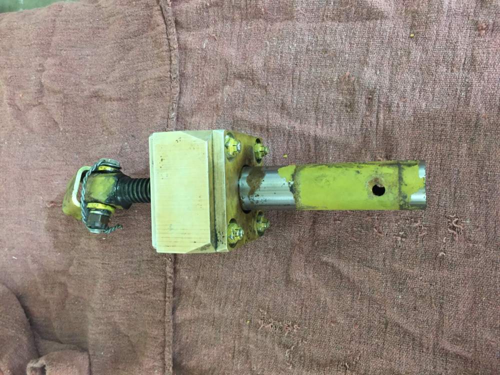
Yes, bolts #2 and #4 for us. Here's a picture of the unit just after removal.
-
For what it's worth, that exactly matches the numbers for our 1976 M20F, just one year off your 1977 M20J. Because the airplane is in a partnership, costs are tracked very closely.
-
Questions about M20F and Mooney's in general
Vance Harral replied to nathan lively's topic in Vintage Mooneys (pre-J models)
As others have said, plenty of room for large-frame individuals in a Mooney. But to be clear, the "small cabin" complaint about Mooneys isn't totally imaginary, for two reasons. The first is, the seat is closer to the floor of the cabin than other aircraft in the same class, such that your knees are less bent and your legs stretch further to the rudder pedals. This gives the Mooney more of a sports-car feel. as opposed to an SUV feel. Some like this, some don't. Second, the instrument panel is closer to your body. The upside is it's easier to see and reach everything. The downside for some is it can "feel" cramped to have the panel closer to your face. I bring these things up not as a criticism of the design, but just to make you aware so you're not surprised the first time you sit in one. If you understand the legs-out-in-front and close-instrument-panel aspects of the design, it will be easier to notice you have plenty of head/shoulder/elbow/leg room. -
What's with posting videos of violating regs...?
Vance Harral replied to gsxrpilot's topic in Videos
Turns out that's illegal in practice, as well as unwise. It's true you can fly IMC in class G without a flight plan or clearance and not violate 91.173. However, the FAA is officially on record as saying they consider flying IMC in Class G without a clearance to be a violation of 91.13. A copy of the letter of interpretation is available at https://www.touringmachine.com/images/ifr_checkride/IFR_Class_G.pdf -
True airspeed not what book says
Vance Harral replied to Supercop0184's topic in Vintage Mooneys (pre-J models)
10K pressure altitude at 40 degrees Fahrenheit is a little over 11K density altitude. In my airplane, the difference is about 4 knots. Doesn't seem to account for 100% of the delta you're seeing vs. book numbers, but that's at least some of it. -
True airspeed not what book says
Vance Harral replied to Supercop0184's topic in Vintage Mooneys (pre-J models)
While there's some truth to this, as a CFI, I've frequently traced complaints about "not making book performance" to pilots who aren't actually using the charts correctly. As an example, flying at 10,000' indicated on your altimeter is not going to give you the true airspeed from the 10,000' line in your POH unless the atmosphere is at standard conditions - not even if you're a test pilot in a brand new, perfectly rigged airplane. If you're crossing the Rocky Mountains enroute from Ft. Worth to Durango, the temperature at 10,000' indicated is frequently much warmer than standard. It would not be unusual for the density altitude at 10,000' indicated to be around 12,000', where the published book numbers for true airspeed are going to be slower for a normally aspirated airplane. Given that you don't mention OAT or density altitude anywhere in your original post, maybe a misunderstanding about the POH tables themselves accounts for some of the discrepancy? -
oil leaking from edo-aire prop governor
Vance Harral replied to Vance Harral's topic in Vintage Mooneys (pre-J models)
Not a bad idea, we might give that a try. I appreciate the reassurance about letting it ride a few weeks. Don't want to do that for very long, though, as the volume of oil it's leaking is bad enough to easily mask other problems should they occur. Our goal isn't "bone dry", just "dry enough to be able to detect a change". We'll likely have the shop address a couple of other issues while waiting on the prop governor, e.g. the rubber couplings on the drain-back lines from the rocker compartments are seeping, oil sump gasket is oozing a bit (may or may not have some luck torquing the bolts there), etc. This engine is right at 2000 hours (and 27 years) since overhaul, so it really doesn't owe us anything. But compressions, oil analysis, and borescope all look good, and we feel like a few small oil seeps here and there aren't reason enough to pull the trigger on a full overhaul - even at the 2000 hour point. However, that strategy is only reasonable if you keep track of where the oil is actually leaking from, and ensure it's not something like a crack in the case. -
oil leaking from edo-aire prop governor
Vance Harral replied to Vance Harral's topic in Vintage Mooneys (pre-J models)
Thanks for the replies so far. We've decided to R&R the governor for either replacement or overhaul and are in the process of scheduling the work with our local shop. A complicating factor is we have an ADS-B installation coming up in about two weeks that requires flying the airplane to the avionics shop, and we don't want to miss our slot. The local consensus is it's not an excessive risk to live with the prop governor leak a few weeks until the ADS-B installation is complete, so that's probably the direction we're headed. We got a recommendation from LASAR on prop governor overhaul: Truespeed Aero Governors. They work on older governors, approximately $600 to overhaul if the core is good. If it's not, they have a couple of options for replacement. We're hopeful an overhaul will work out, as in our opinion, the PCU5000 cost is too large and the weight improvement too small to be attractive. -
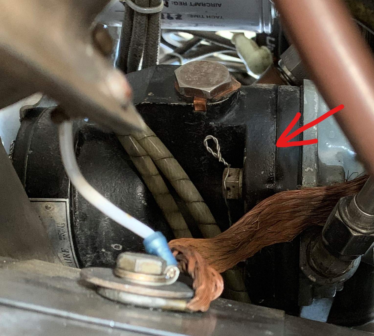
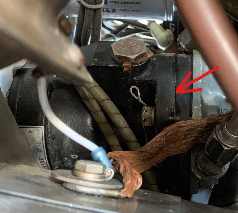
Not a new topic and a few other threads open on this sort of thing, but one always craves input on their specific problem. Below is a side view of the Edo-Aire 34828014 propeller governor installed in our 1976 Mooney M20F. This governor was overhauled in October of 2005 on our watch, and has about 1150 tach hours time-in-service since then. We don't have any operational problems with it - takeoff RPM is right at 2700 and it holds well with no hunting - but a recent investigation into oil leaks has established there is a significant leak at the seal pointed to by the red arrow. It's tempting to start by applying a little extra torque to the mounting bolts to compress the seal, and see if that stops the leak. But a lot of people pooh-pooh that approach, and with good reason - it's a band-aid at best (not to mention a real PITA to remove and re-do the safety wire). The real question I have, though, is what's the nature of this seal? Does one have to overhaul (or at least IRAN) the governor to replace it? Looking at a picture of a used one for sale, it appears the interface where the oil is leaking doesn't simply come apart when the mounting bolts are removed, but rather is integral to an assembled unit. So even if one was inclined to try extra torque on the mounting bolts, it's not clear to me that would actually compress the seal in question. Second, if an overhaul/IRAN is warranted, I'd like to hear opinions on doing that vs. replacement. I'm aware some owners here have replaced their "antique" Edo-Aire and Hartzell governors with a new PCU5000 or similar. I'm also aware some shops won't work on these older governors, as we had to hunt around for a shop that would do so even in 2005. But honestly, the Edo-Aire unit has served the airplane well for decades, is working fine at the moment aside from the leak, and the benefit of replacing it with a "new" design is unclear. What say you?
-
Ram Air Door Opens On Its Own At Cruise
Vance Harral replied to apenney's topic in Vintage Mooneys (pre-J models)
Our knob doesn't look like either of the photos above. I realize this is a terrible photo, but for what it's worth... The 76 F model is a bit of an odd duck. The interior is in many ways more like a 77J than a 75F.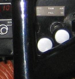
-
Ram Air Door Opens On Its Own At Cruise
Vance Harral replied to apenney's topic in Vintage Mooneys (pre-J models)
Hmm... Our '76F has no twist lock, at least not as noted on the placard (I've never tried to twist it). The ram air cable has always been very stiff to actuate, not sure if that's by design or due to lack of use. -
What Does Airspeed Switch Look Like?
Vance Harral replied to MBDiagMan's topic in Vintage Mooneys (pre-J models)
Interesting how Mooney switched back and forth. Our 1976 M20F has the squat switch, no airspeed switch. -
Moving to the next size up screw just delays the problem. Eventually that one strips, then you've got to go even bigger, and so on (ask me how I know). For the last 10 years or so, I've just kept a box of trim screws handy, and I periodically replace the ones that fall out, knowing they'll just fall out again soon. A technique suggested to me once which sounds promising but I haven't actually tried: use a dimpling tool to dimple the hole in the aluminum that receives the screw, then tap the dimpled hole for the next size up screw. The idea is this creates more surface area along the thread path, for the tap to cut and for the threads to hold purchase against.
-
There's a rule of thumb floating around that 1.0 hours of tach time = 1.2 hours of operating time. It stems from flight schools that operated airplanes with no Hobbes meter, but wanted to charge for time from engine start to engine stop regardless of power setting. When we first bought our Mooney and everyone in the partnership was doing transition training, we tracked both tach time and "stopwatch time" (from engine start to engine shutdown). Over the course of almost 100 hours of tach time that first year, the 1.2 multiplier turned out to be spot on. It's even pretty close for instrument training with lots of long approaches at reduced power. Obviously the 1.2 multiplier isn't correct for a long cross-country flight, but pretty good for local hamburger runs and training flights.
-
Legal question - Runway usage - non-towered airport
Vance Harral replied to Seth's topic in Miscellaneous Aviation Talk
This seems to be the crux of the debate. At my uncontrolled home drome, it's approximately 150 feet from the hold short line to the center of the runway. Taxiing from the hold short line to a full-stop, aligned-with-the-runway position (e.g. for a classic short field takeoff technique) takes about 10 seconds, same as midlifeflyer says. This means I can "buy" 10 seconds of gap time by performing a home-grown-line-up-and-wait (HGLUAW) maneuver while another aircraft is still on the runway, vs. waiting until they exit. But if I plan to smoothly accelerate from the hold short line into a takeoff roll - which is not only my common practice but actually results in a slightly shorter takeoff point - the gap time I can "buy" with HGLUAW is even less than 10 seconds. In that environment - i.e. at my home drome, with me, in my airplane - HGLUAW is silly. The risk of doing so is arguably small, but the benefit is nil. Because when you're talking about literally a single-digit-number of seconds, no reasonable person can claim there is only room to safely squeeze between landing airplanes using HGLUAW. Marauder says in his case the delta is 30 seconds, and I have no reason to doubt him. Maybe a bigger airport with bigger runways, more distance from hold short line. Other folks may not be comfortable with the rolling start technique, etc. I just know that I've never personally been at an uncontrolled field where I felt like HGLUAW was the difference between a polite reasonable departure, vs. bullying into line ahead of landing aircraft. Put another way, if I think there's room for me to get out between two landing aircraft, it makes no difference whether I start from on the runway or from the hold short line, so why not take the latter option? On a related note, I picked up a trick from an old CFI a while back that I like. When using LUAW anywhere - towered or not - consider "lining up" not aligned with the runway center line, but rather cocked 30 degrees or so to the left. This lets you look back and check for traffic landing on top of you, and in most cases gives you an "out" to quickly taxi clear of the runway in an emergency (perhaps into the grass). When cleared for takeoff, just finish aligning the airplane with the centerline as part of the takeoff roll. -
Concur with Don and David. It will likely quit again, and it will likely be a failure of the transducer itself. Ours exhibited this exact same intermittent failure pattern, and was ultimately fixed by replacing the transducer. I did look carefully at the old one after removal, but I was never able to establish if the impeller was hanging up, or the connective wiring cracked inside the potted epoxy. Solution is the same either way: replacement.
-
Another upvote for Arapahoe Aero. We do most of our maintenance done at our home drome (KLMO) but take the airplane to Arapahoe Aero for the occasional Mooney-specific issue (most notably patching fuel tank seeps). Always had good service.