Vance Harral
-
Posts
1,550 -
Joined
-
Last visited
-
Days Won
6
Content Type
Profiles
Forums
Blogs
Gallery
Downloads
Events
Store
Everything posted by Vance Harral
-
I've been pretty happy with PIClife: https://www.piclife.com/ Bought a 20-year term life policy 10 years ago. As Skates97 says, by the time the term is up, I won't need the life insurance any longer. No aviation exclusions on my policy. Note that PIClife is essentially a broker, they work with different underwriters to find you a policy. My underwriter is Lincoln Benefit Life.
-

Question on Brittain Service & Maintenance
Vance Harral replied to Jpflysdfw's topic in Vintage Mooneys (pre-J models)
We called Brittain last week about an issue with the solenoid that seals the altitude reference chamber in our B-5 autopilot. They are in a "slow ramp up" mode with the new owner. Not much available in the way of parts (we wound up buying a salvage part), and it's unclear if they're doing any new development (e.g. integration with Garmin G5). Mostly they appear to be just keeping the lights on, answering the phones, and sending occasional support documents at this time. I'm cautiously hopeful Brittain will remain a viable concern, but I'd keep your expectations low for now. -
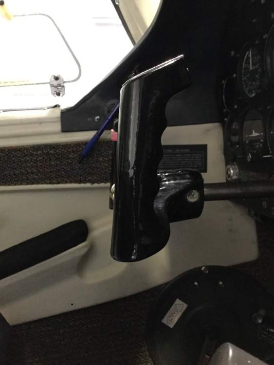
Thanks for the help, Marauder. Unfortunately, based on an educated guess about your serial number, the yoke shafts that were in your airplane before your upgrade are likely not the same part number as the ones in our airplane. I also note that the blueprint pics you posted don't include our serial number. The last of the F models are a bit of a strange flock. Mooney was in the midst of changes that would become the J, and many of the parts in our airplane appear identical to those in a 1977 J, despite having different part numbers (I suspect it's the same actual part, but renumbered). You can see this in the applicability chart for yokes and yoke shafts. S/N 22-1179 through 22-1245 and 22-1247 through 22-1305 have yokes like your old ones, and spec P/N 710005-506 for the right hand yoke shaft. S/N 22-1246 and 22-1306 and on have the newer rams-horn style yokes as in the J, and spec P/N 710005-508 for the right hand yoke shaft. I don't know the difference between a 710005-506 and 710005-508 shaft any more than I know the difference between a 710005-508 shaft and the replacement 710072-508 shaft, but one presumes there is some sort of difference. The J parts manual specs P/N 710064-502 for the early J model yoke shafts. Again, I don't know if that's really any different from the one in our airplane, or just the same part with a new P/N. I suspect this is the sort of thing where only Mooney knows the full story.
-
This is a cautionary tale about maintenance-induced failures. AD 77-17-04 requires 500-hour inspections of yoke shafts. Our 1976 M20F actually left the factory with ram's-horn yokes and large-diameter yoke shafts of the type found in M20J and later models, so one is tempted to argue the AD "shouldn't" apply. However, the AD is technically applicable to all M20F models, and the associated SB M20-205B only permits discontinuance of the inspection if the OEM P/N 710005-508 is replaced with P/N 710072-508. I don't know what the difference is between a 710005-508 shaft and a 710072-508 shaft, but there is no record of a replacement of the former with the latter in our logbooks. Hence, we've dutifully pulled the yokes off every 500 hours for the inspection. The AD was due again at this year's annual, and when we tried to remove the set screw that takes up the slack, the head broke, leaving most of the screw embedded in the yoke, with no way to turn it. Various techniques were tried to extract the screw: drilling, screw extractors, etc. A half day's worth of labor by professional mechanics was expended trying to solve this problem. Their ultimate solution was to simply wrench the yoke off the shaft, and this has scored the shaft pretty badly. The head A&P at the shop has polished the score mark, multiple A&Ps have opined that the shaft is still airworthy with the score mark, and they're willing to sign it off as airworthy. We're "mostly" OK with this, primarily because the shaft in question is on the co-pilot's side. But we'd just as soon replace the shaft in the near future. So now we're on the hunt for a replacement. None of the salvage shops we've contacted has this item in stock. LASAR has reached out to Mooney on our behalf, but Mooney says they'd have to fabricate a new one. We're waiting on the quote, which I expect to be astronomical. Really hoping @Alan Fox, @acpartswhse, or someone else here on the boards has a line on a replacement yoke shaft. We do generally trust the shop, and believe the risk of continuing to use this yoke shaft is low. But the no-apologies fix is to replace it. Anyone have a source for this particular item?
-
Yep. They climb up the mains into the wheel wells, enter the wing where the retract rods pass through the wing to the wells, and thence through the holes in the wing ribs to wherever they like. Ask me how I know. Some Mooneys have "rat socks" where the retract rods enter the wheel wells, presumably in part to prevent this. Our airplane doesn't. It's unclear to me whether it left the factory that way, or if some prior owner removed them.
-
iPad Mini in Mooney? Mount type? Location?
Vance Harral replied to Michael Williams's topic in General Mooney Talk
+1 on the Steelie ball. Easy to pop the iPad Mini on and off the yoke quickly, in either portrait or landscape orientation, and I can tilt it around to various angles to avoid glare.

-
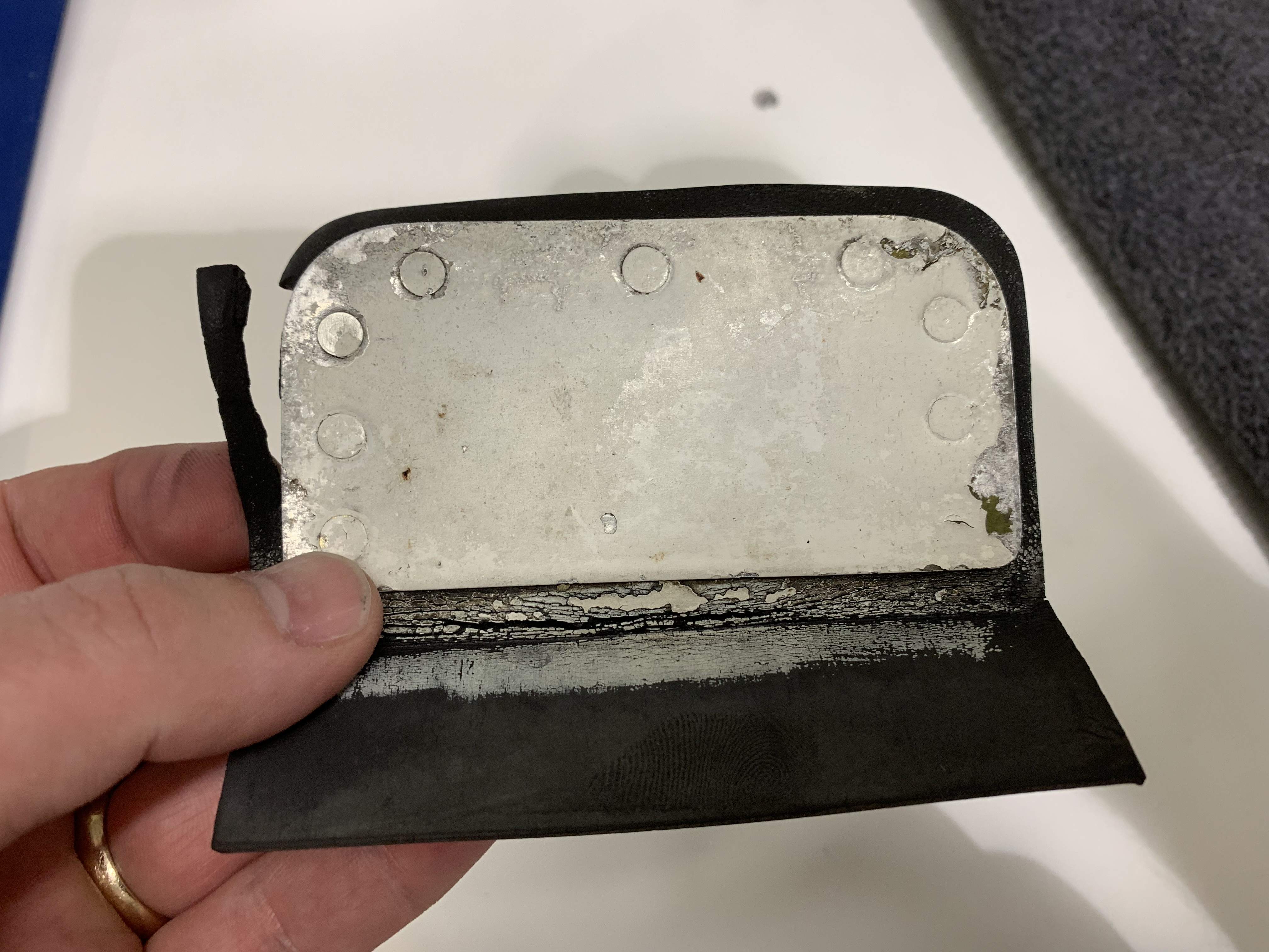
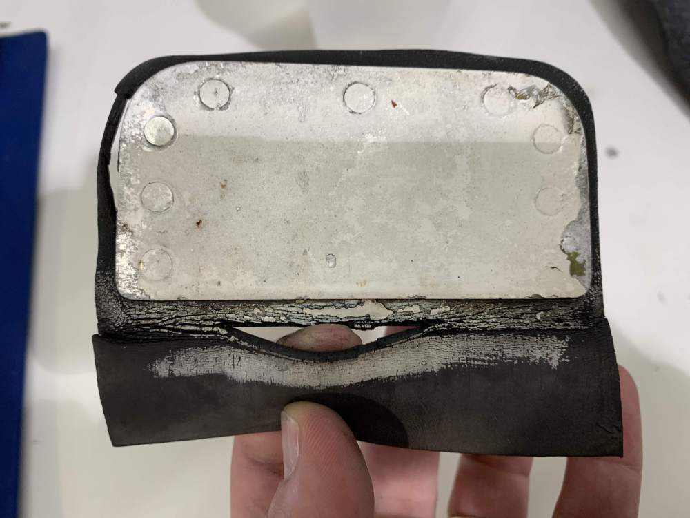
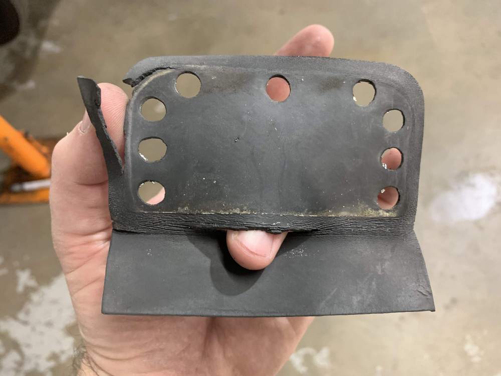
I should clarify. When I said I only had to re-do 3 of the 9 rivets, I meant that I replaced all 9, but I botched 3 of the replacements, and had to drill them out and start over. So I actually placed 12 rivets total. In addition to the rubber seal, the ram air door consists of three pieces of metal: two flat "sandwich" plates, and a third dimensional piece of metal which captures the actuator plate. RLCarter is correct that you have to drive an initial set of 3 rivets to fasten just the two the "sandwich" plates around the rubber seal, then the final 6 rivets go through all three pieces of metal.
-
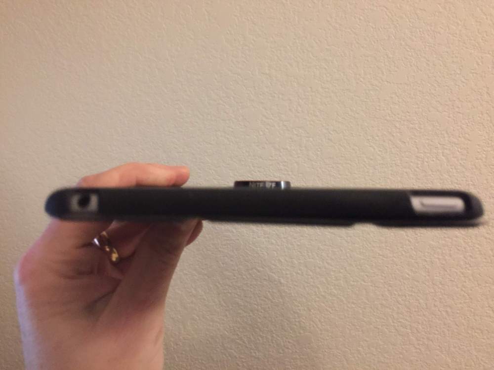
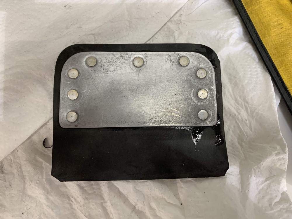
Last July, @chrixxer graciously shared a "never again" story about foreign material in the intake of his M20F here: Mooneyspace collectively identified this as a portion of the ram air door seal. I got an uneasy feeling when I read the story, because we've never replaced the ram air door seal in 15 years of ownership. In fact, there's no record of ours ever having been replaced in the logs, and I think there's a good chance it's original from 1976. Last fall, I took a close look at the seal, and it definitely showed signs of cracking. I made a note to look at replacing it during the annual this spring, and ordered a new seal from LASAR a couple of weeks ago. So... we removed the ram air door yesterday, and found this: Here's what it looks like after drilling out the rivets and removing the aluminum plate "sandwich" around the seal: New seal from LASAR was only about $60, and I got to practice my riveting skills: It's not difficult to remove the door. Just remove the air filter, pull the ram air knob to open the door, and remove the three screws that secure the actuating plate to the door itself. After doing so, the door slides right off the actuating plate, and can be pulled out the front of the cowl. Yes, you have to drill out the old rivets and install new ones, but I'm a total noob at this, and I managed to do it without damaging anything (I only had to re-do 3 of the 9 rivets. ). For those of you with the ram air door - whether you use it or not - strongly encourage you to take a look and consider replacing the seal if you haven't done so in a while. When you get to looking at how the assembly goes together, it's pretty obvious that if a piece of the seal comes loose, it just goes right into the fuel servo. At $60 for the seal and maybe 1-2 hours of labor for a professional (it took me about four with adult supervision), it's cheap insurance against a potentially catastrophic failure.

-
That's indeed possible, and in fact likely. The purpose is to protect you, the owner of the airplane. Since the pilot flying the airplane was "qualified", the insurance company will reimburse you for your hull loss, and for any liability attributed to you, in a timely manner. They are then likely to try to recover their costs from the pilot. This is why smart pilots flying non-owned aircraft (particularly CFIs) either carry their own independent non-owned insurance, or insist on a waiver of subrogation from the insurer of the airplane they are going to fly.
- 80 replies
-
- 3
-

-
- airspeed insurance agency
- insurance
- (and 3 more)
-
Yes, though the details varied in each case. In one case, all the underwriter required of the new pilot was a "checkout" from a CFI, i.e. any CFI was effectively empowered to decide when the new partner was competent to be insured. That was nice, especially since one of the partners was a CFI at the time, and therefore had a vested interest in deciding when the new partner was ready.. The two other cases involved some nominal amount of dual instruction, I think it was 10. I do recall one case where our existing underwriter wanted the new partner to accumulate something like 35 hours of make-and-model time before being insurable. We thought that was unreasonable, and simply worked with our broker to switch to an underwriter with more reasonable requirements.
-
This is the same story we got from multiple avionics shops when we looked into it earlier this year. Everyone agrees it's possible to connect a G5 to a Brittain autopilot. But doing so legally on a certified airplane requires either a FSDO field approval, or waiting on a hopefully-resurrected Brittain to complete the process of publishing certified drawings for the connection. We're biding our time for now, hoping Brittain is alive enough to complete the drawings. If that doesn't pan out, the most straightforward option would be to finally give up on the B-5 after many years of sorta-faithful service, and install a GFC-500 along with the G5(s). While this is a lot less expensive than it used to be, it would still be a hefty chunk of change.
-
Over the course of the last 15 years, we have on three separate occasions added new partners to our policy who had no instrument rating, no Mooney time, and essentially zero complex time. This is on a 1976 M20F with a hull value of about $60K, and the traditional $1M/$100K sublimit liability. In each case, the cost of our policy for the first year of participation by the new partners increased from the $1200-ish range to the $2700-ish range. Assuming the market hasn't changed in the last 5 years (which may be a bad assumption), I'd guess the hit would be somewhere between $1000-$1500 for the first year.
- 80 replies
-
- 1
-
-
- airspeed insurance agency
- insurance
- (and 3 more)
-
Prop governor problem
Vance Harral replied to chriscalandro's topic in Vintage Mooneys (pre-J models)
I was contacted by the folks at Truespeed today with a clarification to my statement about a "pin" wearing on the PCU5000. Truespeed says: The component in the PCU5000 which you referred to as a pin is actually an idler stud. In this type of governor, this stud also serves as the relief valve body. The idler bearing which is in the idler gear, turns on this stud and eventually there is wear on the stud. So, unlike in other governors where an authorized Repair Station would remove and replace a stud when it is worn, the PCU5000 manufacturer specifies that the governor must be returned to the factory and they would replace this stud. Naturally this is not a free service, and there is a substantial cost for this, not to mention the additional time and freight that would be involved. All governors have their pros and cons. In the end, when the time comes, it is up to the owner to decide which governor to go with, but this choice should be made with a reasonable knowledge of what to expect when it is time for repair or an overhaul. A good governor repair station should be able to advise their customers about this. I sincerely appreciate the follow-up from the shop on this. Truespeed carries the PCU5000 and they think it's a good governor, arguably best in class for those who don't mind paying a little more for new vs. an overhauled McCauley or Hartzell. On a related note for those interested, our overhauled McCauley governor is installed and working well after about two hours of test flying. However, we did run into a bit of a snafu during installation. Our installation uses bolts rather than studs to attach the governor, and the housing of the McCauley differs from that of the Edo-Aire in such a way that it's difficult to get the bolts inserted - the head of the bolt interferes with the governor housing on the way into the mounting hole. Seems like there's always some complication when you don't replace exactly like-for-like, not even when the replacement part is on the TCDS. -
I've seen too many reports of Mooneys dropping a wing during stalls to believe every airplane which exhibits that characteristic is severely mis-rigged, or flown by a ham-fisted pilot. Rather, I think it's more likely a characteristic of an airfoil which is more sensitive in the post-critical-AOA region. Remember that when the critical angle of attack is exceeded, lift does not instantly go to zero, but rather just reverses trend to a negative slope: Some airfoils have a relatively shallow slope just past the critical AOA. With these airfoils, a small difference in AOA between the left and right wings is not going to induce a significant rolling moment. Other airfoils have a steeper slope past critical AOA, and are more prone to roll. The steeper the post-AOA slope, the more "penalty" there is for a less-than-perfectly-coordinated stall. This is true regardless of whether the imperfect coordination is imposed by a less-than-perfect pilot or less-than-perfect rigging (including placement of the stall strips). I did my CFI training in our M20F, including the full stall series of trim stalls, cross-controlled stalls, and so on. I won't speak for short- and long-body airplanes, as I agree with @ArtVandelay that the different airframes likely have different characteristics. I won't even speak for airplanes other than our particular specimen. But based on experience in that airplane with a multi-thousand-hour "Gray Eagle" "CFI (not Don Kaye, but similar), I don't think it's a significant risk to fly a mid-body Mooney completely into the stall break for training purposes, even in the dreaded skidding turn. Yes, a skidding stall does cause the airplane to roll significantly in the direction of the low wing, and it felt like an E-ticket ride the first time. But a prompt push on the yoke and application of top rudder resulted in a normal recovery, and no more than about 60 degrees of bank (it feels like you've gone completely knife edge the first time, but not really). Based on this, I don't feel any need to "ease up on the stall" or "recover at the first indication of buffet" when training. Note in particular that the current FAA Private Pilot ACS tasks on stalls call for the applicant to "recover promptly after a full stall occurs". It's true the FAA has been refining the language in the ACS recently, but the current version most certainly calls for a full stall. Don't conflate this with the slow flight task, which the FAA currently wants to involve absolutely no indication of an impending stall. Finally, don't confuse flying the airplane into a full stall and promptly recovering, with flying the airplane into a full stall and holding it there to perform a "falling leaf" or otherwise just see what happens. I'll let Don tell his own stories, but my recollection is his keep-you-awake-at-night incident involved the latter. I would not teach or even experiment with that in a Mooney.
-
For what it's worth, I've been sharing the pattern with a jump operation at non-towered KLMO for about 15 years. No complaints, and I appreciate that the operation helps keep the airport vibrant. King Airs and Twin Otters as mentioned above. Pilots have been professional and courteous. They do fly very steep descents directly into a downwind or base leg, which I suppose you can quibble with; but they're very good about making crisp position announcements, and the airplanes are large enough it's hard to miss them. They sometimes make intersection takeoffs, and occasionally will land in one direction and take off in another when winds are calm; which again some may quibble with. But I've never seen them do anything to suggest they feel they have priority over other traffic. On the contrary, I've seen them make 360s for spacing, extend for inbound traffic on instrument approaches, and wait their turn at the run-up pad/hold short line, all in deference to piston singles, while feeding two turbines. The main contention I've observed around the field seems to come from people who don't have a good grasp on spacing in the presence of significant speed differential. e.g. someone in a 172 might turn crosswind to downwind at about 70 knots, and feel they've been "cut off" if the King Air enters a mid-field downwind in front of them. It's only about a mile of spacing, but at 50+ knots faster, the jump aircraft is not creating a separation hazard. I do worry a bit about transient traffic. Jumpers drop essentially right over the airport, and descend and land between the runway and a normal downwind leg. This is not in conflict with the traffic pattern, except for mid-field overflights. Specifically, an opposite-side entry where you cross midfield at 500' above pattern altitude and circle back for a 45-degree entry is a bad idea, as is flying directly over the airport above pattern altitude as a navigational reference point. In the former case, transient pilots should get a clue when they tune the AWOS, which specifically adds a recording requesting pilots to avoid mid-field overflights. But if you're just passing through, you may not listen to the AWOS. Still, there's never been an incident or even a close call - that I'm aware of - in those 15 years. Overall, a net positive for our airport. Happy to have 'em.
-
Thanks to @Bryan and @kortopates for the informative posts, and apologies to @BaldEagle if I've sidetracked the thread a bit. Hopefully he finds the discourse helpful.
-
Have you actually tested how this failover works, maybe by ejecting the FS510 from the GTN? I understand that in principle the iPad hardware and EFB software could drop the AHRS data stream from the 510 and seamlessly pick it up from the 345. But I wouldn't be surprised if it's not that simple in practice. It's common for connectivity stacks to try to re-establish a connection with a lost device for a while (or forever), before switching to some other source.
-
No Flightstream devices of any kind in our airplane at this time, only the GTX 345. Connecting is straightforward, as there's only one wireless device installed. My experience with GTX345+FlightStream combos is one-off rides in other people's/club's airplanes. Given that those setups only broadcast one device to pair with, it appears those airplanes were either mis-configured, or perhaps deliberately configured for "simplicity" vs. "maximum connectivity". No idea if the owners understood the limitations they were living with. ... which raises an interesting question for avionics shops. Given that many customers have only a tenuous understanding of the technology involved, I wouldn't be surprised if the shops generally configure installations such that only one BlueTooth or WiFi device is broadcasting. Otherwise, a healthy percentage of their customers are going to constantly be connecting to the wrong device, and coming back to the shop complaining something is wrong with the installation. And you can imagine the headaches for a rental operation. With the increasing number of portable and panel-mounted gizmos with wireless connectivity, this problem is only going to get worse.
-
For what it's worth, I've always updated my cards right at the hangar using a laptop hot-spotted to my cellphone. Nav database is about 12MB. Safetaxi and obstacle databases are about 6 and 4 MB, respectively. Even the terrain database is only 24MB. Usually takes less than 60 seconds to download on 4G/LTE, and doesn't even show up as a blip on my data plan.
-
Definitely a nice feature. But again for those following along, this only works if you run Garmin Pilot. If you prefer some other EFB app, you'll either need to keep downloading databases manually onto the card, or maintain a Garmin Pilot subscription in addition to your preferred EFB. Thanks for the detailed info on BlueTooth connections, Bryan, really appreciate the helpful contributions.
-
Thanks Bryan, that's excellent news. We currently have no FlightStream devices in our own airplane, my experience is with other airplanes, that I'm now thinking don't have all the radios enabled in the Connext menu. This certainly increases my interest adding an FS210/510 to our setup, despite already having the GTX345. Just to be clear... if you connect a PED to the 510 via BlueTooth, that PED can show ADS-B weather and traffic? The 510 obviously isn't an ADS-B receiver itself. But I'm guessing that as long as ADS-B data is available in the Connext Hub (as put there by the GTX 345), the 510 can access and transmit it. If so, that would effectively allow 4 PEDs to receive traffic and weather: two via the GTX-345 radio, and two via the FS 510 radio, right? But now for the wildcard... the FS 510 runs $1500. For half that cost I could buy an Aera 660, which I understand can be hardwired to the GTN and receive data streams via the hardware. I had previously thought that was the only way to get an additional connection to weather and traffic data. That option isn't wireless, though.
-
I understand your point that there are multiple BlueTooth radios in the various gizmos. But in all the GTN/GTX/FS installations I've seen (which admittedly is a small set), Bluetooth connections are managed exclusively through the Connext hub of the GTN, and there is only one discoverable device for PEDs to pair with. Therefore, only two connections total for the entire system. If you look in the GTX 345 Pilot Guide, for example, it gives explicitly different pairing instructions for a GTN/GTX combo vs. a GTX 345 standalone device. It would be nice if there were multiple, independent discoverable Bluetooth devices as you imply: one for the GTX 345, a different one for the FlightStream device(s), and so on. But as far as I know, it Just Doesn't Work That Way (TM). If you've laid eyes and hands on an installation that actually does work that way, I'd love to hear about it.
-
Best as I can tell, the 2 BlueTooth connection limit is an architectural limit of the Garmin "Connext" architecture, based on the BlueTooth hardware they use. Doesn't matter if you have the FS210, FS510, GTX345, whatever - only two devices connected at once. Even as a fan of Garmin, with Garmin equipment in my airplane, I consider this a real and frustrating limitation. I frequently fly 2-pilot IFR training missions with a buddy. Each of us has an iPad. I'd like to also link up my phone and use it as a dedicated traffic display, but I can't do that with the 2-device limit. Other vendors use WiFi links, with virtually unlimited connections, which I think is a superior solution. I've heard it argued that you want to be sitting in your airplane on the ground with your iPad connected to the FBO's WiFi for last minute updates, and simultaneously connected to your panel devices via BlueTooth. But I think that argument is a stretch.
-
What do oil stains on an engine block tell you?
Vance Harral replied to M20 Ogler's topic in General Mooney Talk
The Lycoming IO-360-A1A in our 1976 M20F had staining of the type you describe when we bought it in 2004. Still has it, still going strong 15 years and 1000 hours later. Periodically the oil blowing and dripping around the engine compartment gets bad enough that we get nervous and chase down the leaks. To date these have amounted to either seals, gaskets, fittings, hose clamps etc; or minor seeps from case bolts we're told aren't worth worrying about. But we've never done anything major like pulling a cylinder, R&R'ing the oil pan, etc. We just live with a certain amount of leaking. I feel like the key is look as hard as you can for actual cracks in the case and cylinders. If you can't find any, a bit of leaking and staining seems to be just par for the course. -
The database concierge feature in the Flightstream 510 only works with Garmin Pilot at this time, no love for Foreflight. If you're not willing to switch, maintain a subscription to both apps, or bet that Garmin and Foreflight will work something out in the future, consider saving $500 and installing a Flightstream 210 instead.