

Steve W
-
Posts
582 -
Joined
-
Last visited
Content Type
Profiles
Forums
Blogs
Gallery
Downloads
Events
Store
Everything posted by Steve W
-

new sim rules for ifr currency in effect
Steve W replied to DXB's topic in Miscellaneous Aviation Talk
I think this is much of it: https://www.faa.gov/regulations_policies/advisory_circulars/index.cfm/go/document.information/documentID/1034348 I'd guess more stuff lives here somewhere: https://www.faa.gov/about/initiatives/nsp/ Honestly, I'd love to be able to afford one and put it at the local airport, maybe with a credit card swipe -
I can't yet say how accurate my resistive senders are on the EDM 900. They're not fully calibrated as the plane isn't sitting level and doesn't yet have an engine, but I did a bit of magic with the old gauges to get them accurate enough for a ferry flight. Since they're typically(with 32 gallon tanks) calibrated every 8 gallons(0,8,16,24,32) I'd expect the worst case to be 4 gallons off assuming your senders work properly to begin with, mine are from 1994 and haven't given me trouble with the old analog gauges so we'll see. It's fairly easy to display the raw data that's used for the calibration so the pilot could get that data each time before adding fuel and keep a log, and then after enough samples work with an A&P to check/update the JPI calibration table again. Or if the data doesn't make any sense when graphed, then investigate other issues.
-
My Dream Gadget Just released - Garmin G500 TXi
Steve W replied to JohnB's topic in Avionics/Panel Discussion
I'd assume the VS and Altitude is coming from the G500 Txi via the GAD 43e. "Altitude Preselector with Collins APS-65; KAP/KFC 150; KFC 275/325; S-TEC 55X, 60-2, 65, PSS. (KFC 200 expected 2nd quarter 2013.) Vertical Speed Controller with KAP/KFC 150; KFC 275/325; S-TEC 55X, 60-2 65, PSS" from the GAD 43e page: https://buy.garmin.com/en-US/US/p/62760#additional -
TruTrak Autopilot Pre Order's / Status Update
Steve W replied to Jeev's topic in Avionics/Panel Discussion
If you don't have a backup Attitude Indicator I'd recommend putting one there per AC 91-75, from there it's up to you. L3, Sandia, RC Allen, Garmin, MidContinent, etc. -
New Panel - Aspen 2000 (goodbye vacuum system)
Steve W replied to byrdflyr's topic in Avionics/Panel Discussion
My take on the documentation is that the RAD(930) or light(900) should be front and center above the attitude indicator. And so that's where mine is/will be, on the blanking panel where the cluster used to be, new panel someday, just the JPI for now. Also, I don't think I'd consider pushing the 900 over to the right stack. With a 930 or MVP it would be fine, but my I think one of the benefits of the 900 is it can be close in, and it's sort of small and less easy to read than the larger models. -
Yea, but they're not in Oregon, even if everyone in California doesn't know there's anything north of San Francisco.
-
Yea, but seeing that on a pulled cylinder would have been a sign there could have been other problems hiding, like the oil pump housing and gear and at least one other gear with problems, among other things.
-
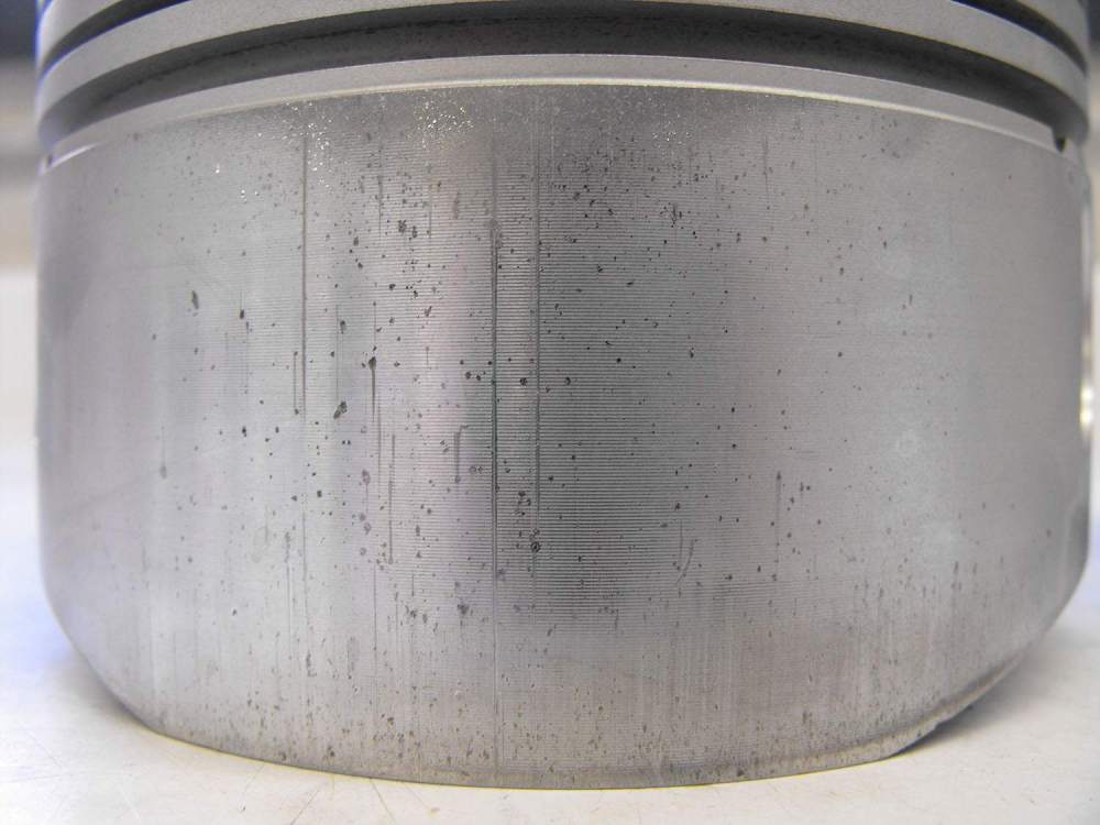
My weedeater has an oil screen, well it has a fuel screen, and since the oil is in the fuel it has an oil screen... But my IO-360 also looks like that. It had a cam failure a few hundred hours before I bought it, which was replaced, and no problems on oil analysis or filter cuts since I bought it, but as part of a prop strike inspection they found similar issues, so I'm upgrading to a full overhaul. So my one regret on my PPI was not paying to have a cylinder pulled which would have immediately found my pistons looking like this:
-
Porpoising leads to gear collapse accident
Steve W replied to kortopates's topic in General Mooney Talk
Well, finally some 'progress'. The case and crank had to be machined due to being out of spec, they finally came back and the shop found extensive issues(pistons, oil pump housing, etc) which appeared to be due to metal that was thrown from when the cam failed a few hundred hours ago(before I owned it) and wasn't resolved at that time. Of course, they discover(or mention) this after the case and other work was done so it's now a little late to just upgrade to a shiny new reman with split mags and roller tappets. So I'm upgrading to a full overhaul since the required repairs(mine+insurance) is 2/3 of the overhaul. Now 3-4 more weeks and maybe I'll have an engine and the rest of the work can begin. -
Getting WiFi in the hangar..
Steve W replied to ragedracer1977's topic in Miscellaneous Aviation Talk
I did this for my hangar, but it's not really something that boiled down to buy X and Y and hook them together. I got a Raspberry Pi with an external USB stick that took an external antenna and then use the internal Pi Wireless as an access point for the hangar. If I were to do it with commercial gear I'd probably look for a bridge or client device with an external antenna port, then connect it via a cable to a normal wireless router on the WAN port. In some cases the LAN port would work and configure the router as just a local access point but that depends on how the main network is setup. Yes, the antenna is inside the hangar, with a metal door, but high enough gain means I have a solid connection about 99% of the time. But, hey, I got to use a fancy looking antenna: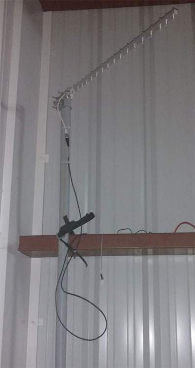
-
Actually, it's not just the plane, but also some engine or prop changes. When I bought mine a sharp eyed pre-buy noticed the tach was not re-marked when it was upgraded to a 3 blade prop. When I sent the documentation to JPI to program the 900 I had to include the STC for the prop as well.
-
Ovation recog light replacment alternatives
Steve W replied to rogerl's topic in Modern Mooney Discussion
I should point out that the stepdown resistor is only going to give 14V if your new LEDs are also drawing 25W. They almost certainly aren't so you're probably seeing more like 26V or so, which most decent LEDs will handle fine. And now... math: E=IR E=Volts I=Amps, R=Resistance in ohms. P=EI P=Watts Old Light: 25W at 14V: 25=14*I: let's call it 1.8Amps Need to drop 14V at 1.8 amps: 14=1.8*R: R= about 8 Ohms So, the existing resistor is about 8 ohms and is dropping(P=I^2 * R) 25watts, basically the same as the light itself since it's cutting the voltage in half. Now, we want the voltage seen across the new light, let's assume it draws 5watts, total voltage still 28V, existing resistor 8 ohms. Mixing the formulas a bit: 28-V=I*8 5=V*I (V here is drop across the LED which depends on current since we assume it's a constant power device) After an exercise left to the reader(mostly because I broke down and used an algebra calculator for the math) we get 26.5V across the LED, 1.5V across the resistor and 0.1875 Amps. The good thing is the resistor is now wasting only about 0.28watts and so it's really not worth digging it out. -
I've had the Tanis removed on my plane as part of my JPI upgrade since it's easier to use the thermowells for all the probes instead of the potentially fragile spark plug thermocouples or the nested heater and thermocouple things. I'm adding a Reiff back in, but not one of the fancy turbo XL ones, just the standard one using the original Tanis oil sump pad. Of course, it's not like it actually gets cold here.
-
According to the parts manual the change was at 24-3154(first new-style) which looks to put the change in 1990.
-
That's why I said some of us. Mine has 4 wing mounted PAR 36.. and I'm also pretty sure I wasn't hallucinating when I changed 2 of them out for LEDs, plenty of cursing though.
-
I have to say, that's one of the best equipped pre-glass panels I've ever seen.
-
So, the horrible website does indicate they'll cover K,L,M,R,S... but as there's no actual specifications, who knows: https://www.illumi-vation.com/shop Also, they have the J listed as a PAR 46 nose light, so obviously they don't want some of our business... I'd likely not buy them anyway, but more competition is always better.
-
Ovation recog light replacment alternatives
Steve W replied to rogerl's topic in Modern Mooney Discussion
I'm thinking of things in the slightly not brighter than the sun range, like these, replacements for backup bulbs, wedge based 921 form factor, rated about 400lumen. I just need to get bored and make a reflector for them and order some T4 sockets, I've found ones in a similar form factor with higher reported brightness but even 400 should be plenty bright in a proper reflector. I originally ordered them to try out in my rear wing tip position lights but they're too large.s.jpg.a69a8912ecdff6dd8bdb5b9cef4465aa.jpg)
-
Ovation recog light replacment alternatives
Steve W replied to rogerl's topic in Modern Mooney Discussion
Simplistic ones might, especially ones rated for only 12V. But the wide input (12-30V) ones have standard switching power supplies on-board, just very very tiny. It's pretty easy to tell, hook it up to a power supply at 12V, increase it to 28V, if the power draw remains roughly constant(V*A) and the brightness remains constant then it's a decent one, if it catches fire then it's not. Note: if they say 'canbus compatible' then you generally don't want them as they have added resistors to increase current draw to fake the car computer into thinking it's a standard filament bulb. -
Legal question - Runway usage - non-towered airport
Steve W replied to Seth's topic in Miscellaneous Aviation Talk
And 91.113 for the right of way rules... Which basically just says you better not still be in the way when the traffic wants to land. -
Ovation recog light replacment alternatives
Steve W replied to rogerl's topic in Modern Mooney Discussion
Personally I think I would have trained the hangar elves to use a wedge base socket(or bayonet) and an automotive LED rated for up to 30V to simplify the installation. Admittedly most of those aren't quite that bright though. It's hard to find the voltage rating and brightness listed in a useful manner. -
The only time I've heard it on the radio in the last few years is when someone decides to say it(and do it) at an uncontrolled field.
-
Alternative to rivets in radio trays?
Steve W replied to Rick Junkin's topic in Avionics/Panel Discussion
Here's a picture I took a while back, accuracy not guaranteed: https://photos.app.goo.gl/jDAwTYL9x3ggxxjN6 (1994 M20J) -
Sagging Engine, Worn Lords Mounts
Steve W replied to GeorgePerry's topic in Modern Mooney Discussion
A dynamic balance is done on the plane as it's as really about the prop and the engine working as a system, much like how tires get balanced once they're actually put on rims rather than in isolation. Here's an AOPA article on the process: https://www.aopa.org/news-and-media/all-news/2018/january/22/propeller-maintenance-balancing -
Sagging Engine, Worn Lords Mounts
Steve W replied to GeorgePerry's topic in Modern Mooney Discussion
New doesn't imply it was actually balanced or balanced well, check the log books for the install and see if they actually dynamically balanced it.


