

testwest
-
Posts
596 -
Joined
-
Last visited
-
Days Won
3
Content Type
Profiles
Forums
Blogs
Gallery
Downloads
Events
Store
Everything posted by testwest
-

Gascolator Gasket 2" x 1/16"
testwest replied to 1964-M20E's topic in Vintage Mooneys (pre-J models)
I called Lynne today at Brown Aircraft and they still can make this gasket for your Dukes gascolators! The price is still $8.01. Great deal!! -
Lubricating landing gear (grease)
testwest replied to Yourpilotincommand's topic in General Mooney Talk
Good info on grease and zerks here -
Voltage indicator blinking before engine start
testwest replied to OR75's topic in Modern Mooney Discussion
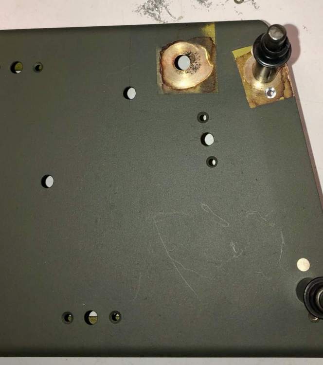
OK, we had this issue on 201JX. With the master switch and the radio master on, but no avionics on and no avionics fan (pull the circuit breaker for the fan), measure the voltage at the battery terminals, and then from the radio bus to a ground in the front of the airplane. The only loads should be the battery master relay and the radio master relay. The front voltage will be lower, but it should be only about .3 or .4 volts lower, due to unavoidable losses through the positive cable that comes forward from the battery to the starter solenoid and thence to the rest of the busses. If it is a lot lower, like more than a volt lower, check where the grounding cable from the negative post of the battery is bolted to the airframe. On ours, the loss was 1.25 volts. Upon removing the ground cable from the airframe (it attaches to the forward avionics shelf in our airplane) I found corrosion and primer between the cable and the structure. The hole on the right is where the battery ground attached. This view is looking downward on the aft left surface of the avionics shelf, and the tail of the airplane is towards the top of the photo. And here is the shelf after clean up. The grounding area was cleaned with a stainless steel bonding brush, then treated with Alodine 1132 from an Alodine pen. This was on both lower and upper surfaces. Also provisions for assured electrical bonding were made where the shelf attaches to the fuselage stringers, one on each side. This is visible under the cleco on the right side of this picture: The voltage drop going forward went from 1.25 volts to .3 volts with this change alone. No wonder 1JX was never a very energetic starter, even with a fully topped off battery. And of course everything was fine with the alternator on, just like the OP experienced.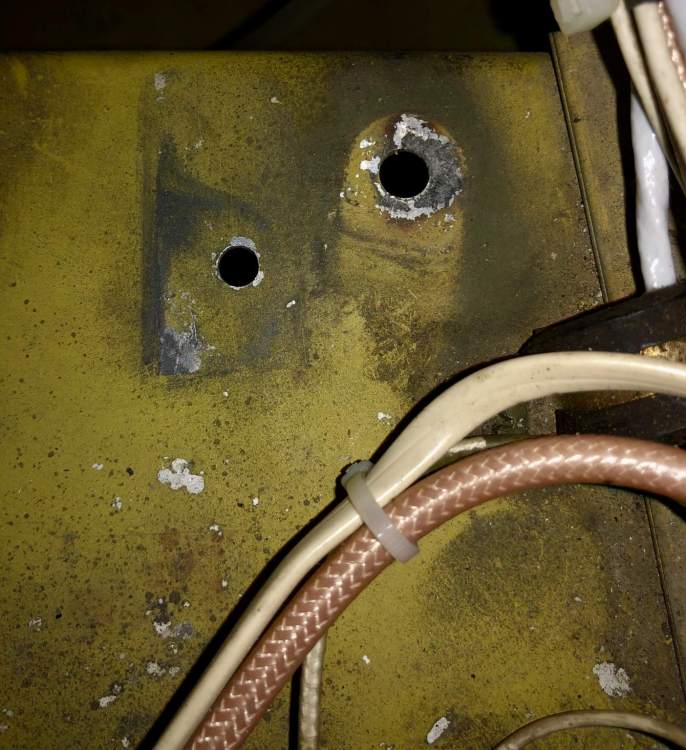
-
PM sent on switches, thanks!
-
Any of the rocker switches available? I am looking for a Radio Master switch (E-T-A type) in black with white letters.
-
That really sounds like you have a big GAMI spread. I bet there is one cylinder that is quite leaner than the rest, and as it goes leaner and leaner, the power in that one cylinder is dropping off significantly. Dude, the data will set you free, please download it and post, or send it to me and I can graph it....it should be a .jpi file.
-
Any updates on this post? I for one am really really curious how those new CMI (Continental Prime) cylinders are working out.....
-
For the OP, can you please post some data from the 900? Be sure to set the data rate at the smallest possible number, I think it is 1 sample each 2 seconds, look in the setup menu for the 900. carusoam 's post to you, above, is solid gold! Remember 1650 deg TIT is a continuous limit, and as such you can momentarily exceed it (like not longer than a minute or so) while leaning, as long as you get back below 1650 on the lean side. Kind of like this: The straight yellow lines are markers, the vertical one is the time and the horizontal one is at 1650 deg F on the left hand y-axis. The TIT lines are the purple and orange, superimposed. Note while leaning the TIT goes above the horizontal yellow line at time 1656:25 or so. (Time on the x-axis). Most people chicken out here, but the richest cylinder is not at peak yet, in this case #4. Stopping at this time would leave this engine (IO-540-S1A5 TN intercooled 290hp) at 1650 TIT, 16 gph, and 360 on the C4 CHT roughly. (Those last two parameters are read from the two right-hand y axes, respectively). So, some cylinders are LOP and other are still ROP. That is why smccray asked if you know you are LOP. It's way too easy to stop early. Just beyond the vertical yellow marker, you can see I settled the #4 EGT about 25 deg F LOP (highest yellow line, reads to the left hand y-axis). The power is constant from there, and the C4 CHT (lower yellow line) then starts a dramatic decrease down to just below 340 deg F over the next minute and a half. Even more dramatic, the lowest blue line is fuel flow. Fully LOP we settle at 13.5 gph. Your new EDM-900 is a treasure trove of data. And I urge you to extract the operating knowledge that is just sitting there waiting!! There are a few of us on MS that just eat this stuff up, and we like nothing more than helping others here. Hope to hear from you more on this thread.

-
Value of a used JPI EDM 800 for 6 cylinder
testwest replied to 231LV's topic in Modern Mooney Discussion
Hmm. Typically the fewer connections the better. I don't think moving those pins around in the d-sub shell would be too difficult. -
Value of a used JPI EDM 800 for 6 cylinder
testwest replied to 231LV's topic in Modern Mooney Discussion
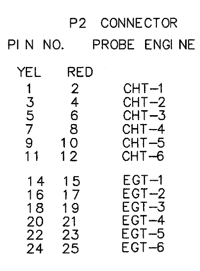
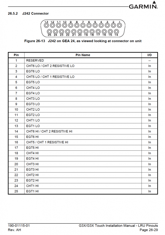
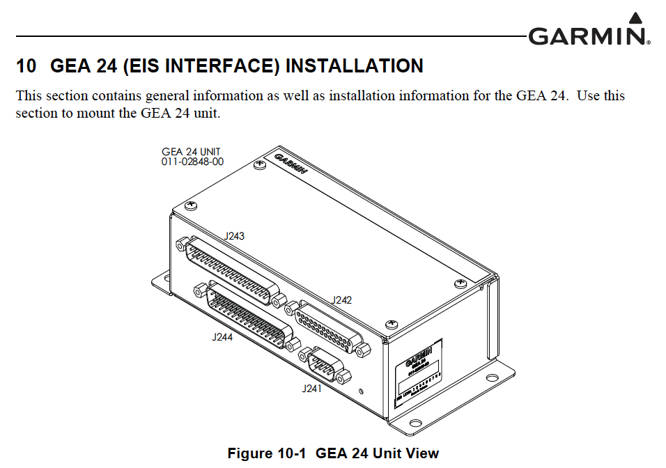
The G3X engine displays are primary. And, from what I am reading, the G3X can use all manner of existing engine probes as installed, even if those probes were not originally part of an approved primary display. Here is the pinout for the EDM-800 EGT and CHT 25 pin d-sub connector: In the G3X, Garmin went so far as to match connector type (but not the pinout) from the EDM-700/800 etc series so that connector plugs into an identical receptacle into a unit called the GEA 24: Here is the pinout, you would have to spend some quality time with your d-sub extractor to move the pins around, but it is sure a lot more cost effective than buying and installing all new probes.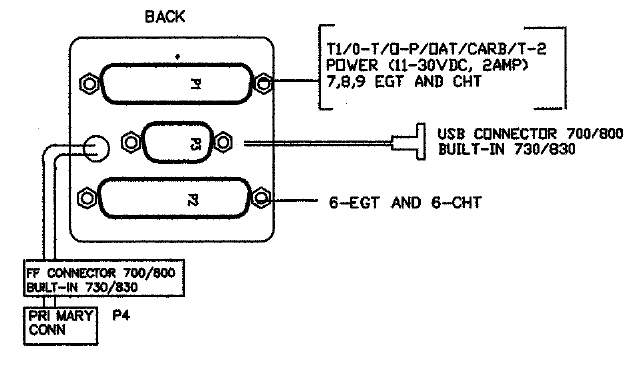
-
Another Sun n Fun Request - Acclaim cowl pix
testwest replied to testwest's topic in General Mooney Talk
Ok, thanks! -
Hi everyone If anybody at Sun n Fun could get some close up pictures of an Acclaim cowling, inlet areas, both exterior and interior that would be awesome. Trying to discern the inlet diameter as well as the interior diffuser area and forward baffling... Am looking at some design details with respect to NASA CR 3405 and how Mooney implemented the design principles for a 6 cylinder turbocharged engine. Bonus points and a free Mooney flight review if you can get a ruler in the pictures for scale!!
-
GLAP has a new solar control gray color, I think it is a UV blocking material. It is more money but a fantastic feature...of course it came out just after we replaced all our windows on 1JX....
-
So, for the OP, the suggestion is, keep the power up, keep the speed up, climb reasonably good and “git on down the road”! As far as CHTs in the climb go, Mooney and the FAA are (were) concerned with a point design condition. Us owner operators are more concerned about balancing performance and engine durability over the long term. So even though the airplane may pass the cooling climb condition flight test, we can smartly get most of the performance in climb rate and velocity made good, while being mindful of engine durability, by the suggestions here....cruise climb, maximum power, manage cylinder temps with speed and/or cowl flaps (in that order), target EGT. Hope this helps.
-
Hi Hank and everyone I wish I had cowling pressure and cooling data! But thanks for thinking of me. My opinion is that the difference between true airspeed and calibrated airspeed can be thought of as a virtual tailwind, going from zero to a pretty decent number the higher you go (all other things being equal). So a cruise climb speed (or quantified cruise climb profile Vz, as many in this thread are using *thanks, it's really cool to see that* ) decently balances the climb rate versus velocity-made-good to the top of climb. The higher speed should help cooling, the Target EGT fuel flows were established to allow the airplane to pass the part 23.1043 requirements. But why is everyone having to work so hard to keep their engines cool in climb, when they are supposed to be able to stay in limits when flown as designed? Here is a stunning master's thesis that might have answers, the premise is that the FAA formulas for correcting flight test ambient conditions to standard may not be correct. https://repository.lib.fit.edu/bitstream/handle/11141/1138/STUTH-THESIS.pdf?sequence=1&isAllowed=y One of the advisors to this paper is my friend (and SETP Fellow) Ralph Kimberlin, with his guidance this thesis is one you can take to the bank. Happy reading!
-
Mooney Aerodynamic Curves (Nerd Alert)
testwest replied to 0TreeLemur's topic in General Mooney Talk
I was not a Mac guy until this program came out. It was so compelling I had to get a Mac to run it. -
Mooney Aerodynamic Curves (Nerd Alert)
testwest replied to 0TreeLemur's topic in General Mooney Talk
Hi Fred Benchmark is a free app on the Mac App store, here: https://itunes.apple.com/us/app/sequoia-benchmark/id1244483544?mt=12 And the primary support and information page is here: http://www.seqair.com/benchmark/index.html There is a massive amount of information on the info page, be sure to get the 1.0 Manual at the very bottom of the page, even though the interface has been updated, the basic computations behind the program are explained here: http://www.seqair.com/benchmark/BenchmarkManual.pdf Be forewarned, however! If you are the least bit aerodynamically curious, I just ruined this coming weekend for you. -
Mooney Aerodynamic Curves (Nerd Alert)
testwest replied to 0TreeLemur's topic in General Mooney Talk
Haha, thanks Hank! But just for the record, the paper was a Master's thesis, not a PhD dissertation. And I am glad to be back, I also made my donation for this year! -
Mooney Aerodynamic Curves (Nerd Alert)
testwest replied to 0TreeLemur's topic in General Mooney Talk
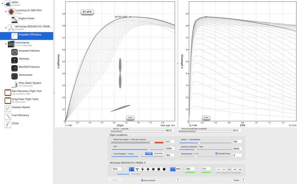
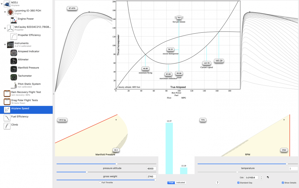
OK! For the OP, Fred2O, here is the drag polar for the M20J, derived from the data in the 1220G POH (which was applicable to our Mooney, a 1977 M20J): Each one of the little "+" symbols is a line in the POH cruise data. For this POH, the best fit to the aggregate data is from the 6000' best power cruise data at 2740 lb GW, and the pink "+"s are from that particular data set. So the zero-lift drag coefficient is .01654, and the best-fit straight line above gives CD = .01654 +.082 CL2 Pretty close to what Skip wrote... that Mooney provided the clean polar as CD = 0.0164 + 0.072CL2 It took a LONG time to enter all that data into Benchmark.....but it could be done for the other models from the POH data. The M20J data are really good though. Curt Lopresti told me during a conversation once about how his dad was so proud of the torque meter they had installed for direct measurement of installed power for the M20J certification, and of course the other two secret weapons were legendary flight test engineers Fen and Dorothy Taylor. So to overcome drag, you need thrust. How much? Using the data set above and about 75% best power cruise, here is what is happening at the prop: Lots of eye candy here. 6000 feet, 75% best power cruise, 150 hp into the prop, 131.2 comes out due to prop efficiency. Even the old McCauley C212 is pretty good at about 87.5% efficiency. To describe this to jet jocks, the M20 goes ~163 knots on ~262 pounds of thrust. This translates to the airplane speed chart for these conditions, here: Cool stuff. Hope you guys like it.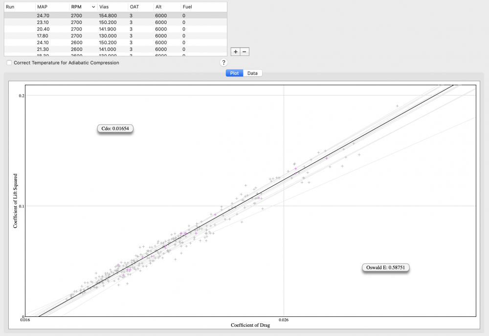
- 92 replies
-
- 11
-

-

-
Mooney Aerodynamic Curves (Nerd Alert)
testwest replied to 0TreeLemur's topic in General Mooney Talk
Wow, how did I miss this topic? OK, for the OP, I have a very neat drag polar for you (clean). Stand by........ -
Another useful idea from Bob Kromer at Summit
testwest replied to Bob_Belville's topic in General Mooney Talk
Here is a movie of KSMooniac flying a back-to-back Vy versus Vz profile. Vy and Vz at KAAO.m4v Using Vz we got to the 19 mile point about 13 knots faster than Vy on about the same gas. -
Another useful idea from Bob Kromer at Summit
testwest replied to Bob_Belville's topic in General Mooney Talk
Here is a picture showing the Vz profile. Sorry it's a brand B...... In a nutshell it shows a Vy climb to nominally pattern altitude (assuming there are no obstacles requiring a short duration Vx climb to clear), then acceleration to Vz. That speed is about 1.3 times published gross weight Vy. No need to adjust for weight, temp, etc....when the airplane becomes performance limited you revert to a 500fpm climb until speed is Vy, then Vy. That performance limit is indicated by the change in slope of the Vz line on the right side of the picture.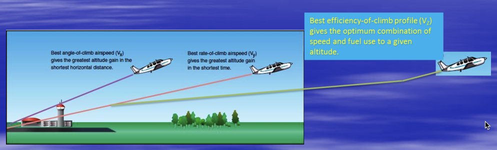
-
Byron is correct. I have used MGS L285 epoxy (Aircraft Spruce)...it is the structural epoxy used to build certificated Cirrus and Diamond airplanes. Yep....it is $142 bucks for a gallon of resin and $35 for a quart of hardener. But worth it. MGS L335 is a little cheaper, not as good on the physicals but perfect for fairing and smaller parts.
-
I would have to drag out my Benchmark models and have a look at the differences....KSMooniac’s prop takes a lot of weight off the nose, meaning less trim drag. Jetdriven has done a huge aerodynamic cleanup includes 80+ hours of wing profiling on his and I think the standard prop...Byron? So there are many trade offs and the answer is not perfectly obvious. What would be nice is a 2 blade composite prop for our airplanes like the Hartzell ASC II used on the Diamond DA-40 XL. 46.8 lbs. By contrast the Hartzell BA prop we have on our J weighs 64 lb. The cost for the STC, well......I wonder if Hartzell made their forward-loss money back on the BA Top Prop program. There were certainly a lot of spinner problems early on. The tip profile starts to make a difference when it is really cold, as the tip Mach number goes up the drag advantage on the very narrow-chord thin tip profiles of the modern blades starts to be significant.
-
Hi Simpson Congratulations on receiving your STCs, that is a big deal! One of your FAA pilots may be K. Lund, he was a classmate at the AF Academy and also in my TPS class at Edwards. Back to topic, sorry for the dumb question, but are the Aspen PFD flight mode annunciators driven by the 3100? I do know the altitude preselect, GPSS and FD all work with it, but have not seen this specific question answered.....


