testwest
-
Posts
588 -
Joined
-
Last visited
-
Days Won
3
Content Type
Profiles
Forums
Blogs
Gallery
Downloads
Media Demo
Events
Everything posted by testwest
-
Hi everyone Since the Mooney Summit was cancelled, I did the Vz presentation I was planning to give at that venue for the local EAA Chapter in Spruce Creek, FL instead. I recorded the video and audio as a "virtual" Keynote (Apple version of Powerpoint). It is in the Safety and Techniques section in Downloads, above. This is a presentation of the concept of Vz, an efficient climb profile for small airplanes. This was my 2012 Master's in Aviation Science Capstone Project (thesis, basically) for Embry-Riddle, and it was judged as one of the top two Capstone projects submitted for the entire year for the worldwide campus. Vz was the subject of much discussion on Mooneyspace a number of years ago, and I was finally able to record an updated video of the presentation. TRT 57 minutes with narration. There are numerous animations and some video in this Keynote presentation which will play as a movie on most computers, hopefully. If someone needs a higher resolution version I can arrange to Dropbox it to you, the hi-rez is about 3.8 gigabytes. Mooneyspace members are free to utilize this video in virtual meetings or EAA chapter functions as they see fit. Special thanks to Scott Sellmeyer @KSMooniacwho was the first subject of the flight test portion of this project. You will see him flying his Mooney 201 briefly in the video. Looking forward to feedback!

-
Introducing Vz - Best Efficiency of Climb for Small Airplanes View File This is a presentation of the concept of Vz, an efficient climb profile for small airplanes. This was my 2012 Master's in Aviation Science Capstone Project (thesis, basically) for Embry-Riddle, and it was judged as one of the top two Capstone projects submitted for the entire year for the worldwide campus. Vz was the subject of much discussion on Mooneyspace a number of years ago, and I was finally able to record an updated video of the presentation for the EAA Chapter at Spruce Creek, FL. TRT 57 minutes with narration. There are numerous animations and some video in this Keynote presentation which will play as a movie on most computers, hopefully. If someone needs a higher resolution version I can arrange to Dropbox it to you, the hi-rez is about 3.8 gigabytes. Mooneyspace members are free to utilize this video in virtual meetings or EAA chapter functions as they see fit. Special thanks to Scott Sellmeyer @KSMooniac who was the first subject of the flight test portion of this project. You will see him flying his Mooney briefly in the video. Looking forward to feedback! Submitter testwest Submitted 10/24/2020 Category Safety & Techniques
-
OK, I submitted the Vz presentation to the Downloads section of Mooneyspace, waiting for a moderator to approve it.
-
I have a good presentation on Vz now, am crunching a video to be Mooneyspace friendly for the files section. The presentation as I recorded it a couple weeks ago was almost 4 gb at full resolution. Will make a new post when it is up. About 57 minutes long.
-
WOT and 2700 RPM, full rich at sea level, use "target egt" to lean on the way up starting at around 3000' density altitude. 25 square destroys your climb performance. Fly the Vz profile, lots of posts here on that, basically 1.3 * Vy or 115 KIAS to start.
-
Replacing ETA Switches with ETA 3120 Seies
testwest replied to Speed Merchant's topic in Modern Mooney Discussion
I ordered one some time ago, it looks like it would be a "reasonable" path. I would talk to the new Mooney company owners on this regarding an approval. As the holder of the type design they would much more likely be able to successfully pursue the change. -
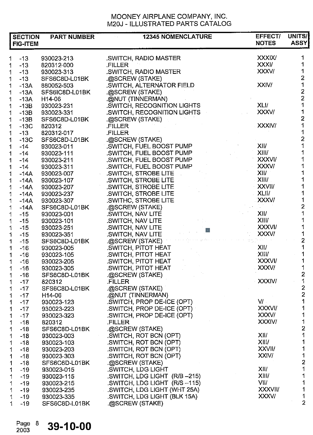
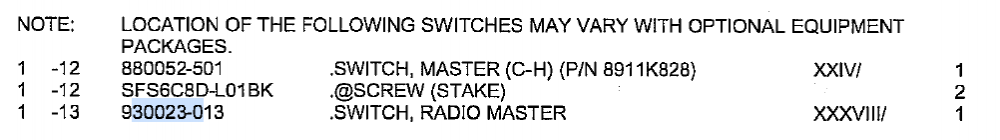
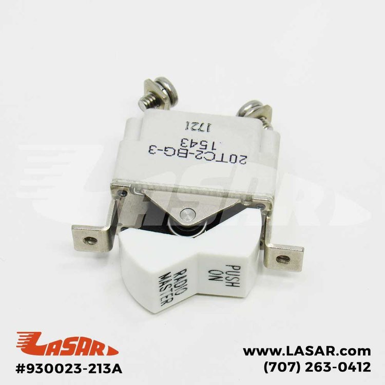
You need a copy of the Illustrated Parts Catalog for your M20J airplane. All of the switch part numbers except for the Master start with 930023-*. The asterisk is a three digit number depending on the type. In the parts list, there will be a bewildering set of switches for each position, you have to match the effectivity of the part number to your airplane....and serial number 1443 matches a lot of effectivity numbers for this section (39-10-00) of the IPC. This is a fun exercise looking up roman numerals in this chart here: Everything about this is a struggle, for the Master switch there is only one, and it is not an E-T-A switch breaker combo. It's a Cutler-Hammer 8911K828, Mooney part number 880052-501. Looking at effectivity XXIV above we see the serial numbers are for #1686 and later, and there is no listing for any earlier model. At least here is a picture: LASAR is out of stock on these, but at least you can see the switch rating. Now, let's do the radio master. From the above, 930023-013 is for effectivity XXXVIII, that is for S/N 001-1463. Yours is 1442, and I guarantee that is a Klixon, not an E-T-A. The white E-T-A switches cut in on s/n 1464, see below: 930023-213, effectivity XXXIX, that is 1464 and on, skipping a few blocks of serial numbers. BUT, WATCH OUT, there are also 930023-***A switches out there, these are Klixon substitutes for unobtanium E-T-As: 3 amps on this one, which is the -3 on that part number 20TC2-BG-3 from Klixon you see there. And the Radio Master is installed "upside down" so when the circuit is open the switch is "on" meaning the radio master relay is closed. It is a real puzzler. If you want a BLACK E-T-A radio master (930023-313) good luck. I got one for our 201 but it took 10 years of monitoring the used markets and salvagers to get one. Even the wiring diagram for your serial number in the Mooney thumb drive is not legible. You will need to go back and forth between the picture above, the parts list and effectivity numbers, and the pictures on LASAR's web site to piece together this puzzle. Good luck....I changed all of the old white Klixon switches on ours to black E-T-As when they were more available...I don't think I would do that again though, since the E-T-A switches (part 41-10-P10 in various amperages) are no longer in production.


-
This $17 extractor is what you need, I think this is the right part number, stand by for more info, I will update this post when I can. https://www.digikey.com/en/products/detail/305183/A1329-ND/15640
-
+1 for C & L Aero. Great shop with a lot of experience and know how. They are who I use.
-
One really fun thing for next year might be to have a Mooney fly-in and visit to Piqua, OH and the Hartzell factory. I have had the tour some years ago, and seeing the history and the current manufacturing effort at Hartzell is really awesome. Their motto is "Built on Honor" and you really get the sense that it is way more than just a slogan when talking to the skilled craftsmen and observing the factory in operation. A true American success story, and highly recommended!
-
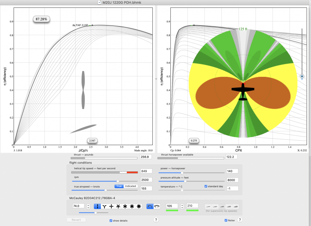
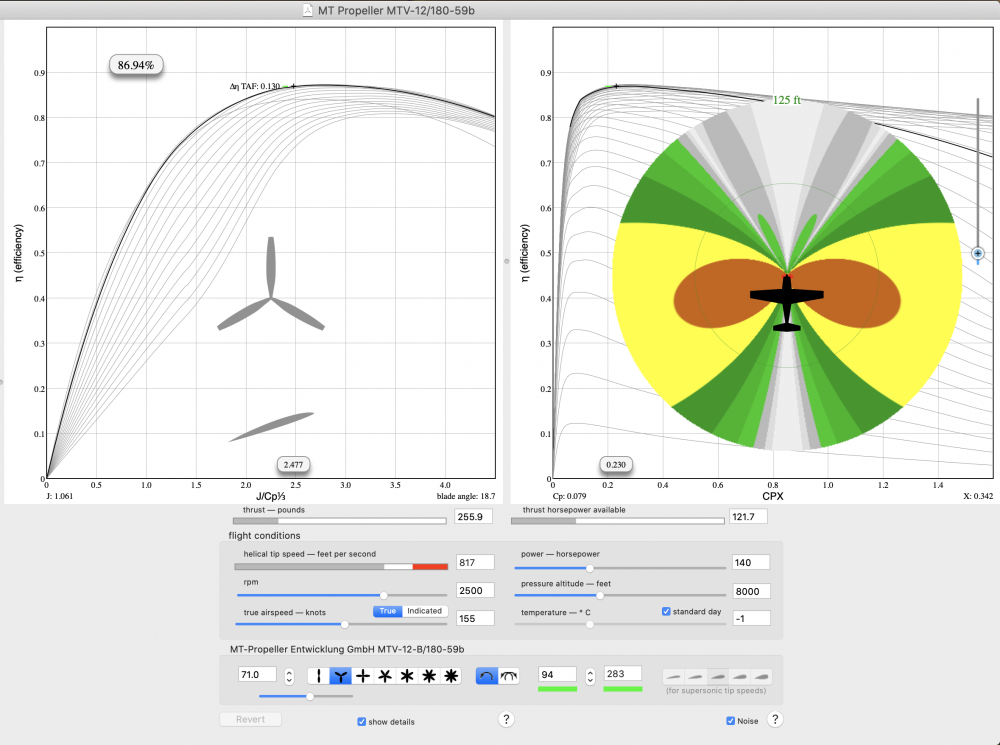
OK, for Tim, the power utilized in making noise is encompassed in the amount below 100%, so about 23% of the power going into the prop is not turned into thrust hp but into something else (noise, thermal transfer, radial outflow, radial drag, entropy and so on). The red area is predicted to be the 125 dB noise footprint from the prop, but the prediction not really useful that close, it is more theoretical (with LOTS of caveats) than practical. For Cliffy, the blade profiles for a two blade or three blade prop designed for the same power loading and speed range are somewhat different. The "induced drag" of each blade comes from producing half the thrust hp on a two blade or one-third on a three blade. The total rotational drag (among other things) tends to favor more blades at a slower speed and fewer at a higher speed. But as I have said, today's blade profiles are very complex and optimized compared to the WWII era versions, so the performance trade-offs are likely overshadowed by other qualities, like smoothness and noise.
-
Yes, that is correct. Realize this noise signature is a bit of an approximation and there are all kinds of unsteady inputs that can't really be modeled. I will say the observations of those who have direct experience with both props on the same airplane are accurate, though, especially the assessment of lesser fatigue after a long flight.
-
OK, here is a cruise comparison between a McCauley 212 74" 2-blade prop and a three blade MT MTV-12-B/180-59b at 71", the first one is the original prop for our 77J and the second is the STC'ed composite (wood) three blade for the same model. Input conditions are 8000 feet, about 155 KTAS, standard day and about 70% power or 140 hp into the prop at 2500 RPM. McCauley: And MT: Some very interesting data here. As expected the 2 blade McCauley is ever so slightly more efficient at cruise, but I would be hard pressed personally to ferret that performance delta out in flight test. The really neat thing is how much quieter the MT is at cruise, as shown by the noise footprint graphic. The calculation of this footprint is by a modified Gutin noise formula, the original of which dates to 1936 and the modification of the formula from NACA Technical Note 1145, written in 1946 and downloadable here (for the curious): https://apps.dtic.mil/dtic/tr/fulltext/u2/a801118.pdf I prefer the dirt-farmer approach to interpreting the noise footprint: The orange area is 100-110 db, or about as loud as a Kiss concert near the front row. The smaller the orange area the better, if you are flying.
-
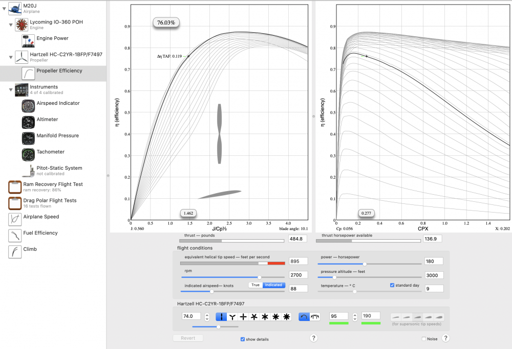
A couple more quick answers, a 3 blade prop has a little better power loading and efficiency (~77.5% instead of 76% as above, for example) at the low speeds, so under the same 88 KIAS climb above you are seeing about 139 hp out of the prop instead of 137 from the BA. Will post the Benchmark model for a Mooney-Hartzell three blade here later today. You are correct on that long floatplane prop. Once out of the water a better noise and efficiency technique would be to get the RPM back off 2800 as one accelerates. If I had a float plane I would go to the trouble to model a climb RPM profile that would keep those tips off transonic as the helical tip speed (rotational speed plus forward speed basically) increases. Benchmark does show the 2 blade BA about 1% more efficient than the 3-blade at a normal cruise, for us around 155 KTAS at 8000 feet and roughly 70% power. Tim you are also correct on that. I can post more model charts if anyone wants to see 'em. And Cliffy thanks for the kind words. Engineering stuff is interesting, and what I try to do is keep it reasonably accurate, brief enough not to be boring, and immediately applicable by the audience in their flying.
-
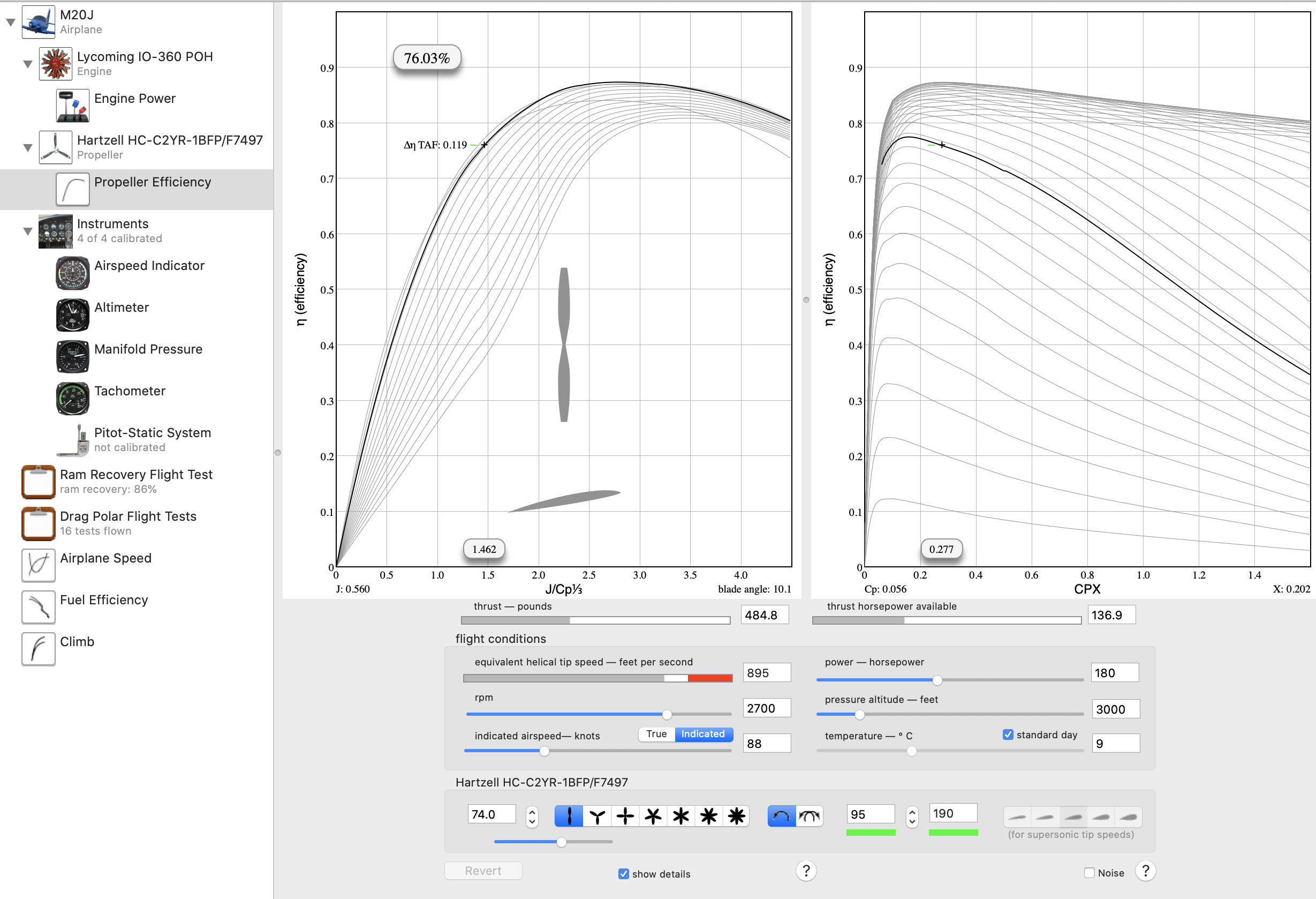
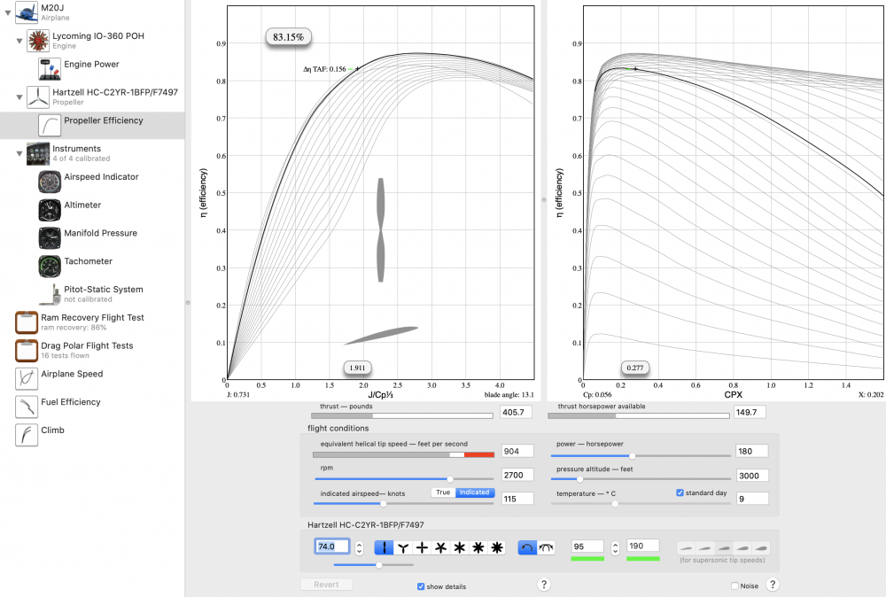
I agree, a great PIREP, O Tree (or should I say King Julien?) For Hank, my thesis was on efficient climb, and I utilized the propeller models in Benchmark to predict the climb performance of several alternative profiles. The propeller performance algorithm in Benchmark is a marvelous bit of programming that makes the Boeing General Propeller Chart (a three dimensional surface chart, published in the Journal of Aeronautical Sciences in January 1943) a dynamic model that can be manipulated. Today's prop manufacturers all use proprietary CFD models to do the same function, but the Boeing Chart (and its Benchmark representation) is still surprisingly accurate even today. The swept, thin tip is a really good shape for reducing noise and transonic drag. CNC machining and very high fidelity computational fluid dynamic modeling made the manufacture of these new props possible. Climb speed has an ENORMOUS effect on propeller efficiency. Let's say you are in a climb at 88 KIAS in your 200hp Mooney with this Hartzell Blended Airfoil prop, passing 3000 feet on a standard day. Your engine is putting about 180hp into the prop hub at this point, about 27"MP and 2700 RPM. (No 25 square OWTs please). The prop is only about 76% efficient here, so you are getting about 137hp out of the prop. Now, without changing ANYTHING else, simply nose over a little and then climb at about 115 KIAS instead: Notice the prop efficiency is now about 83% efficient! There is about 12hp more coming out of the prop. (Sharp eyes will note the thrust force goes down, remember that power is a force per velocity function, see here for more details: http://www.epi-eng.com/propeller_technology/selecting_a_propeller.htm ) Now, the airplane won't have a higher VVI at this faster speed because the drag is going up a little faster than the excess power. But you are getting down range quite a bit faster, on essentially the same fuel burn. The magnitude of propeller thrust hp change with increased speed during climb has not been well understood outside of fairly small flight test engineering circles until recently. For the OP, those square tips were easy to manufacture in the old days, but very bad for blade loading, noise and transonic drag. The three-bladed Hartzell prop is still the old 7282 blade section, meaning the airfoil along the blade span is fairly consistent. The McCauley elliptical prop is a pretty good design and is hard to beat from a performance standpoint, but it is noisier and has more rpm restrictions, at least on the J with its A3 and B6 dynamic counterweights. The Hartzell ASC-II composite prop for the DA40 cited has a wide chord to help get back some of that lost efficiency at the slower speeds that I showed above, but that chord is a little wide for an airplane with a higher speed range, such as ours. Hartzell makes a 3 blade composite prop for the 200hp Van's airplanes, 74 inch diameter with a narrower chord that the Diamond prop, and is better suited for our speed range. See here: The neat thing is that this prop is stunningly light, only 42 lb due to their new light weight RaptorTM hub (the 3 bladed MT for the same application is 46lb.) Would love to see the Raptor on an E or a J.
-
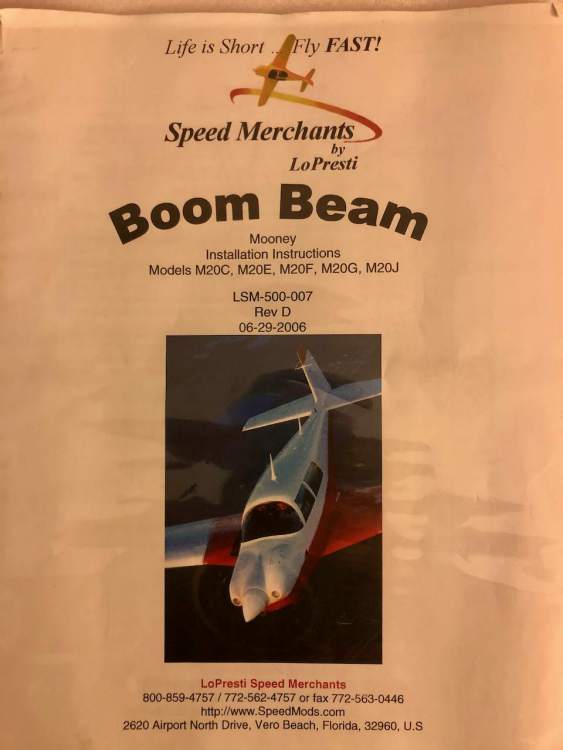
Boom Beam 12V PAR 46 $100 steal it
testwest replied to testwest's topic in Avionics / Parts Classifieds
Done! -
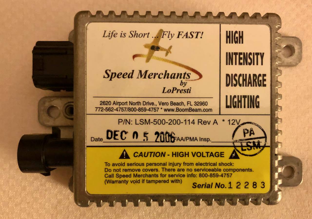
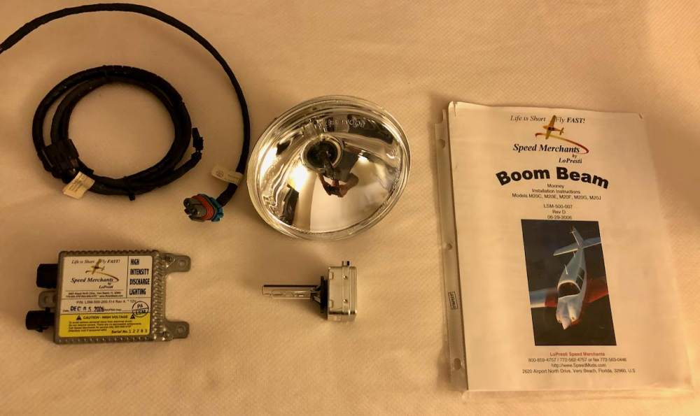
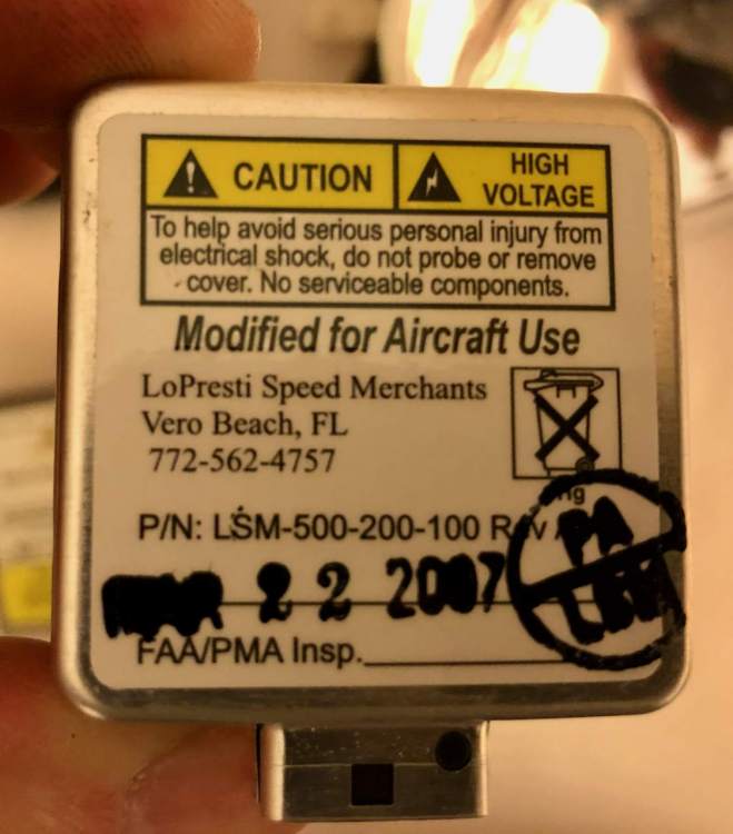
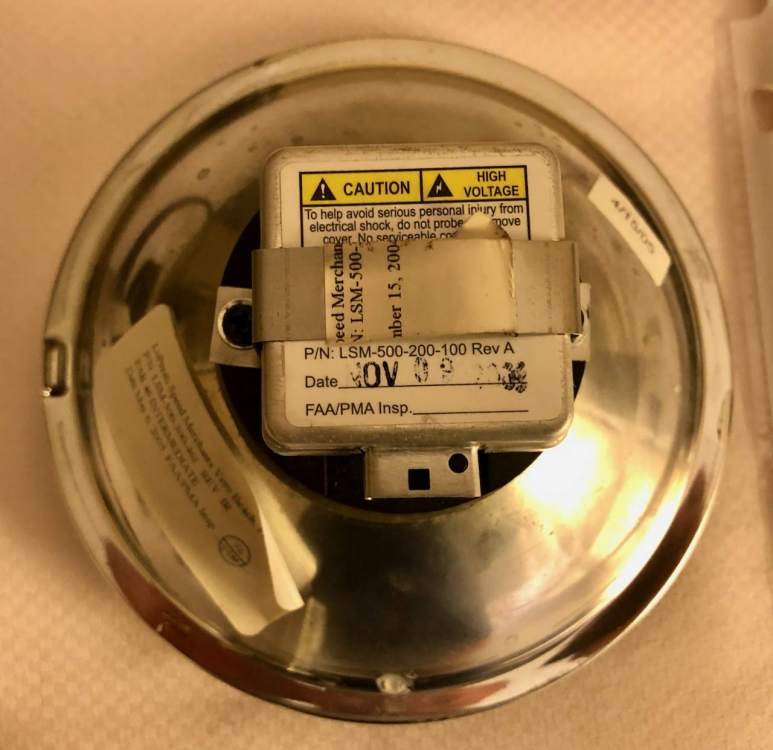
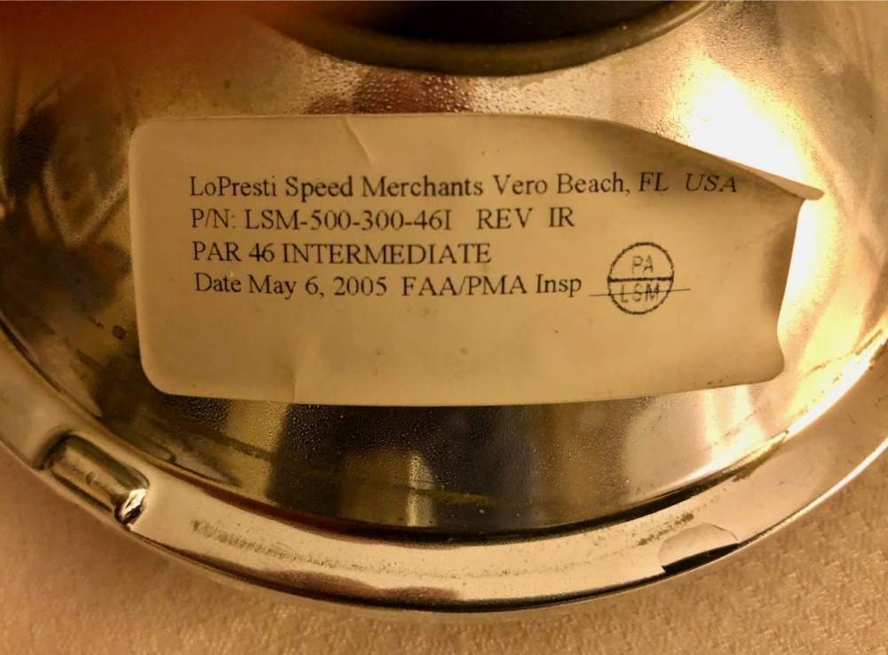
Hi everyone Selling a Boom Beam from our 77 M20J. It is the PAR 46 size, 12V, 35W, only about 10 hours of operation at most, comes with everything in the picture including a spare bulb. Only $100 plus shipping, I am pricing this for a quick sale. Has the installation paperwork, but for a new legal installation you would need to contact Whelen AT, who now owns the Lopresti HID line. This would be best for someone who already has a Boom Beam installed and wants spares. Paypal accepted, send PM if interested!


-
Gascolator Gasket 2" x 1/16"
testwest replied to 1964-M20E's topic in Vintage Mooneys (pre-J models)
Excellent, thanks! I got my gasket from Brown Aircraft already, they responded very quickly. -
Gascolator Gasket 2" x 1/16"
testwest replied to 1964-M20E's topic in Vintage Mooneys (pre-J models)
I called Lynne today at Brown Aircraft and they still can make this gasket for your Dukes gascolators! The price is still $8.01. Great deal!! -
Lubricating landing gear (grease)
testwest replied to Yourpilotincommand's topic in General Mooney Talk
Good info on grease and zerks here -
Voltage indicator blinking before engine start
testwest replied to OR75's topic in Modern Mooney Discussion
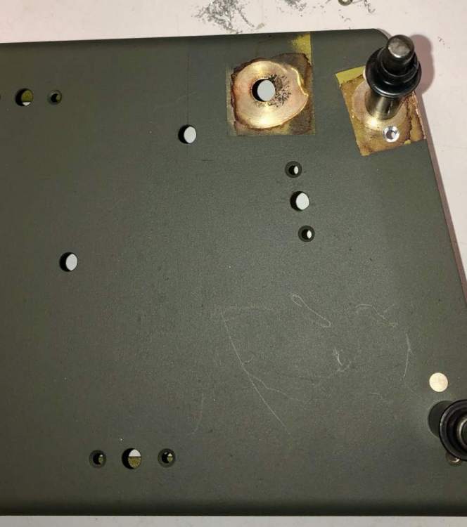
OK, we had this issue on 201JX. With the master switch and the radio master on, but no avionics on and no avionics fan (pull the circuit breaker for the fan), measure the voltage at the battery terminals, and then from the radio bus to a ground in the front of the airplane. The only loads should be the battery master relay and the radio master relay. The front voltage will be lower, but it should be only about .3 or .4 volts lower, due to unavoidable losses through the positive cable that comes forward from the battery to the starter solenoid and thence to the rest of the busses. If it is a lot lower, like more than a volt lower, check where the grounding cable from the negative post of the battery is bolted to the airframe. On ours, the loss was 1.25 volts. Upon removing the ground cable from the airframe (it attaches to the forward avionics shelf in our airplane) I found corrosion and primer between the cable and the structure. The hole on the right is where the battery ground attached. This view is looking downward on the aft left surface of the avionics shelf, and the tail of the airplane is towards the top of the photo. And here is the shelf after clean up. The grounding area was cleaned with a stainless steel bonding brush, then treated with Alodine 1132 from an Alodine pen. This was on both lower and upper surfaces. Also provisions for assured electrical bonding were made where the shelf attaches to the fuselage stringers, one on each side. This is visible under the cleco on the right side of this picture: The voltage drop going forward went from 1.25 volts to .3 volts with this change alone. No wonder 1JX was never a very energetic starter, even with a fully topped off battery. And of course everything was fine with the alternator on, just like the OP experienced.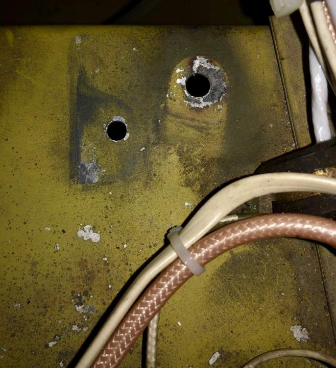
-
PM sent on switches, thanks!
-
Any of the rocker switches available? I am looking for a Radio Master switch (E-T-A type) in black with white letters.
-
That really sounds like you have a big GAMI spread. I bet there is one cylinder that is quite leaner than the rest, and as it goes leaner and leaner, the power in that one cylinder is dropping off significantly. Dude, the data will set you free, please download it and post, or send it to me and I can graph it....it should be a .jpi file.
-
Any updates on this post? I for one am really really curious how those new CMI (Continental Prime) cylinders are working out.....