47U
-
Posts
1,111 -
Joined
-
Last visited
-
Days Won
5
Content Type
Profiles
Forums
Blogs
Gallery
Downloads
Media Demo
Events
Store
Everything posted by 47U
-
Maintenance Manual (106) lubrication chart lists graphite and kerosene for the starter drive. But, I would try some graphite spray. When it dries, it won’t attract dirt.
-
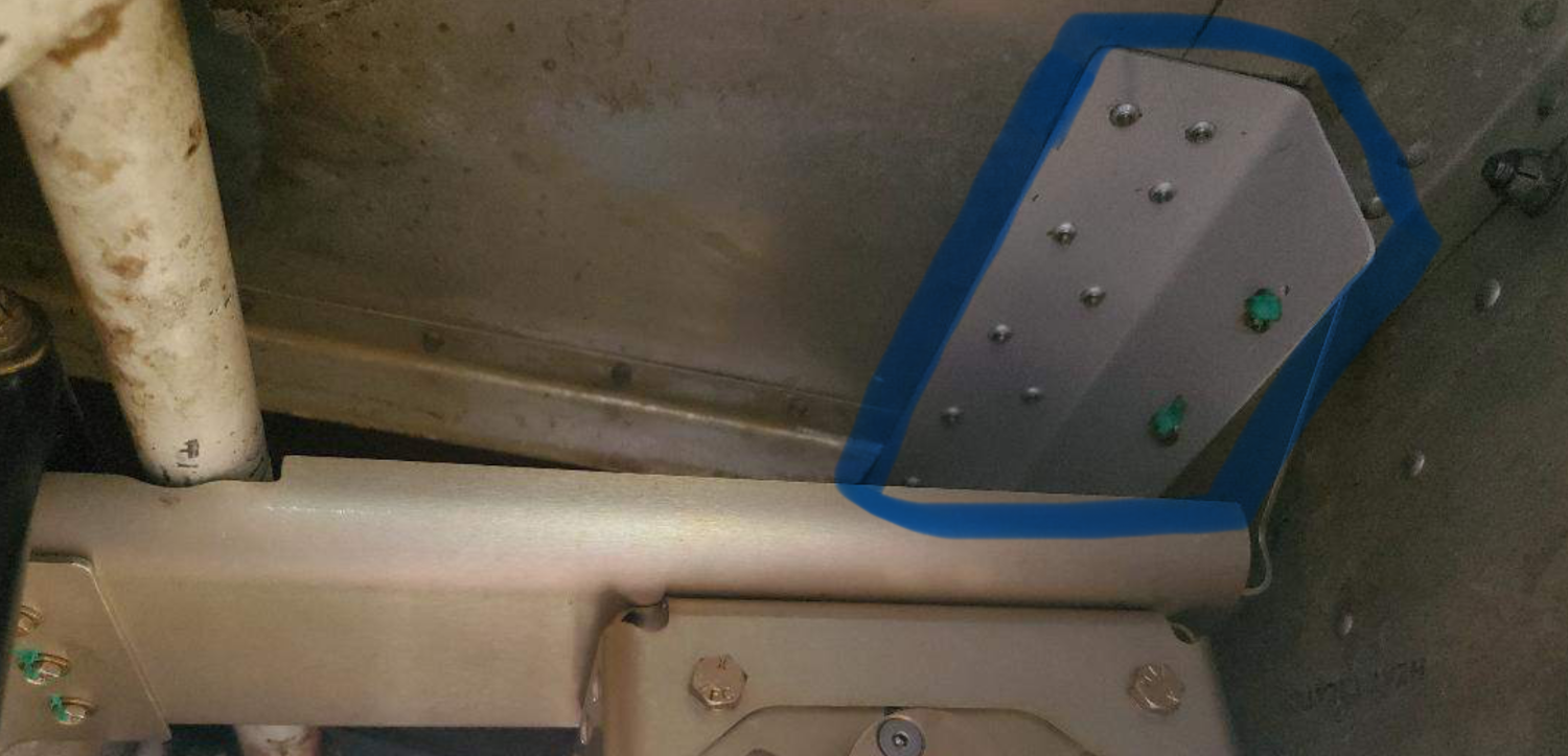
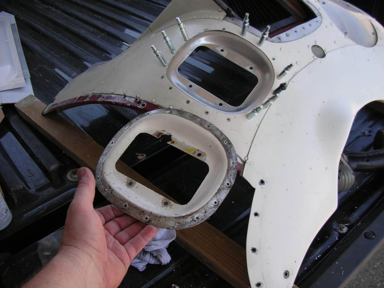
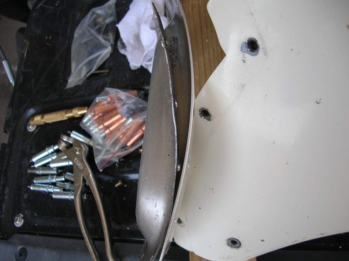
@cliffy Thank you for posting these pictures. Did you fabricate this angle (circled in blue) to support the servo tray aft mount bracket, or was it in the kit? Were the servo tray forward and aft mount brackets you installed in your initial kit order, or did Duncan send them to you as a modification after your kit was delivered? Your servo mount tray didn’t have to be shortened? My servo tray forward and aft mount brackets are bent at 90 degrees, and my servo tray is too long… it’s for a mid-body. Per a draft print Duncan sent me, the servo tray needs to be shortened and the forward and aft mount bracket’s angle changed so the servo tray is installed at an angle slightly off from horizontal… which the reason appears to be to cleanly install the aft servo tray mount bracket through the step support structure on the aft side of the bulkhead. Your installation appears to avoid the structural variances between models in the aft bulkhead. I think I need to contact Duncan… this is progress.
-
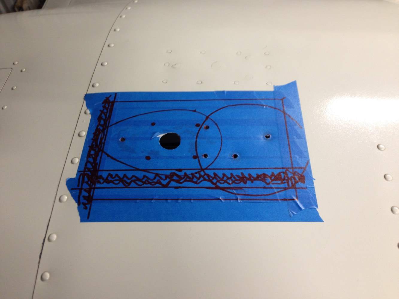
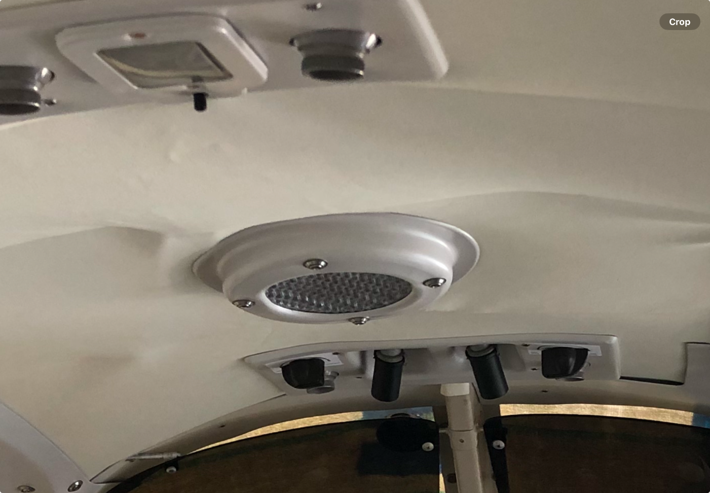
‘63 C model… when I was doing the layout for my gps antenna I was trying to use the same coax hole as a previous comm antenna. Since the fuselage skin is so thin (albeit, not structural), I wanted to do a doubler, but it was complicated by the speaker footprint. Here’s my layout, the speaker mount screws (in the circle) are through the external skin. Remove those screws and the speaker should be able to get fished out through the hole in the headliner after the speaker trim piece is removed. As far as a replacement speaker, there was a thread about that a while back…
-
And the modifications to change the angle of the elevator servo mount brackets was approved on a 337? Which would be my first option. I have the draft drawings and mock’d up the installation, it’s not rocket science. I just haven’t approached my IA to see their opinion, yet. Looking forward to your next report…
-
My logbook says I installed pn 650017-000, Rev G, way back in 2010. They didn’t roll the part number for the thicker bracket, just the revision letter. You are correct, Revision G is made of a heavier gauge aluminum. LASAR sold me the part. If they don’t have it in stock, they can probably source it from the factory. Or, you can call around.


-
A consequence of a 60 year old airplane. There are antennas with offset coax connectors, if that helps, but whether or not it will match the other comm antenna is still a question. Or, at some point move the antenna to the belly with a bent whip? In the end, it’s not really a distraction to the great looks… I should have kept my trap shut. Good work.
-
I think it turned out great. Please post a picture on the ramp with a wide perspective. Now, about those two different style comm antennas on top??? Really nice looking early (‘65) C model. Good work.
-
Welcome… Where are you located? Rags called it, in my opinion. Even hangared, in anywhere but maybe the dry southwest, corrosion may be the deciding factor on whether or not this aircraft can be resurrected. Add up what you think the minimum expenditures for each system would be to get the airplane airworthy. Engine, avionics, airframe… obviously you’re doing much of the work, otherwise the labor bill might be a deal killer by itself. That’s your ace in the hole. Once you have the expected resurrection cost totaled up, ask him what he thinks it’s worth. Then hand him your estimate… once he recovers from the shock, then tell him what you think the labor bill will be. Hopefully, he won’t need any smelling salts, or an AED.
-
That was my thought. How is the braided strap grounding through a bolt that’s encased in the isolator. Maybe the ground was through the control cables??? Checked tailpipe for continuity, 0.7 ohms to an unpainted screw (ship side) on the cabin door hinge. Continuity to the same screw from the right tank filler neck, 0.3 ohms. I forgot to check continuity to the LASAR tie down…
-
https://mooney.com/wp-content/uploads/2020/12/SBM20-180.pdf On my ‘63C, the aircraft battery negative terminal is grounded to the engine. Therefore, all airframe mounted electrical system’s path to ground is through the engine. I replaced the engine-to-airframe ground strap when I redid the engine mount isolators. It was connected to the right lower isolator bolt and was in bad shape. Removing the isolator bolt finished it off. I moved the engine-side end of the airframe ground strap from the isolator bolt to a ground lug on the engine case. And I’m going to check my tailpipe for continuity to the airframe, too.


-
Was there anything in the suction screen in the sump?
-
We had a sensor with an intermittent issue. Ring’d perfectly on the ground. Finally, found a cannon plug (100+ pins) on a pressure bulkhead with one pin that was reversed, the crimp end was on the female side and the female end was crimped. Pressurizing the bulkhead in flight created enough flex that the connection was intermittent. A Lockmart tech rep found it. Those guys were mostly ancient (compared to the blue suiters) but they knew their shit.
-
@Pinecone
-
I’m guessing the SoS box is on the cockpit side of the firewall. Pull the top cowl and inspect the wiring from the left mag back to the firewall. If there’s a bad wire, it’s probably on the engine side. The P-lead wire is probably shielded (unless it’s been replaced with shielded wire under the insulation). If that looks ok, then pull the avionics access and inspect that wiring from the SoS box to the firewall. If still no smoking gun, depending on your level of mx ability, remove a plug lead from a plug on the left mag and install a plug in it. Ground the plug to the engine and have someone energize the SoS. DON’T ENGAGE THE STARTER! And, don’t get shocked. I removed my SoS years ago, and never had to troubleshoot it, so I don’t remember if it buzzes that means for certain it’s making spark. There’s an SoS troubleshooting guide, probably in the downloads section. I still have my SoS box, in case you need one.
-
‘Oh Lord, stuck in Lodi again…’ When the engine starts after releasing the key (and the right mag fires, as Hank describes), have you done a mag check? Does the left mag make spark then? I’m guessing hearing the shower of sparks buzzing means that box is probably working, but an inspection of the wiring between the shower of sparks and the left mag (as MooneyMitch suggests) might reveal an issue. Which side of the firewall is your shower of sparks. Do you have a 201 windscreen?
-
EricJ is right. A 6-point crow’s foot would be the best option. Along with the heat and penetrating oil suggestions. Is corrosion suspected? If so, Kroil (Aero Kroil) is my go-to penetrating oil.

-
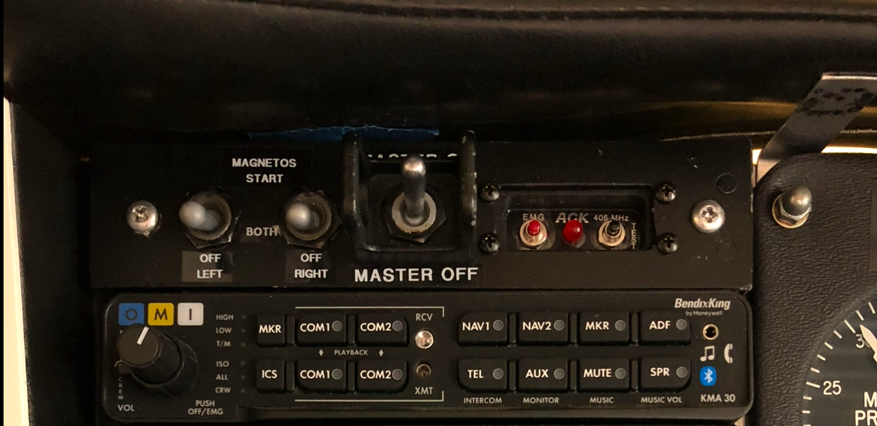
It was Pilot Coyote (since sold his Mooney and left the forum) that inspired me to go to toggles after he said the Citabria he flew had toggles, as do some twin engine aircraft. I found a paper online written by an RV builder and modified his schematic. My IA called it a minor alteration. I mounted them above the radio stack, where nothing else fits (the early M20s had the mag switch up there) and moved the Master switch up there, also. It bought me some space on the pilot’s panel. I thought it might be awkward during engine start, but it’s not at all. Left hand on the switches, right hand on the throttle. I did put a ‘cage’ around the Master, so as to not bump it if I am doing mag checks in flight (with turbulence). I found the switch cage (guard) online, supposedly it’s design came from the space shuttle. So, being easily swayed by nostalgia (and future telling of the history) that’s where I went. (I’ve posted this before, so my apologies, but there’s new members all the time so… there you go. That’s my excuse.) I also think the locking toggles are a good option if you’re going that direction.

-
Continuing the revival of this post… In 2010, Dan sold me a new oil cooler mount ‘Bracket’ pn 650017-000 REV G which is much thicker aluminum than the original. No issues since. The IPC Manual 205 also lists pn 650049-000, but I’m not sure what that’s about.
-
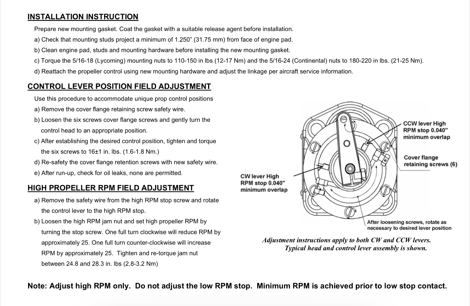
 Presumably… if an adjustment on the governor high rpm stop doesn’t get you to 2700. Adjusting the limit stop is a counter-clockwise turn on the stop (screwing it out) resulting in more travel on the arm, so I think you’ll get there. Otherwise, that’s maybe a question posed to Cody Stallings…
 -
https://cdn.prod.website-files.com/648893d6ed845c1087937b37/648893d6ed845c1087937c06_INSTALLATION-GUIDE.pdf Here’s a screenshot…
-
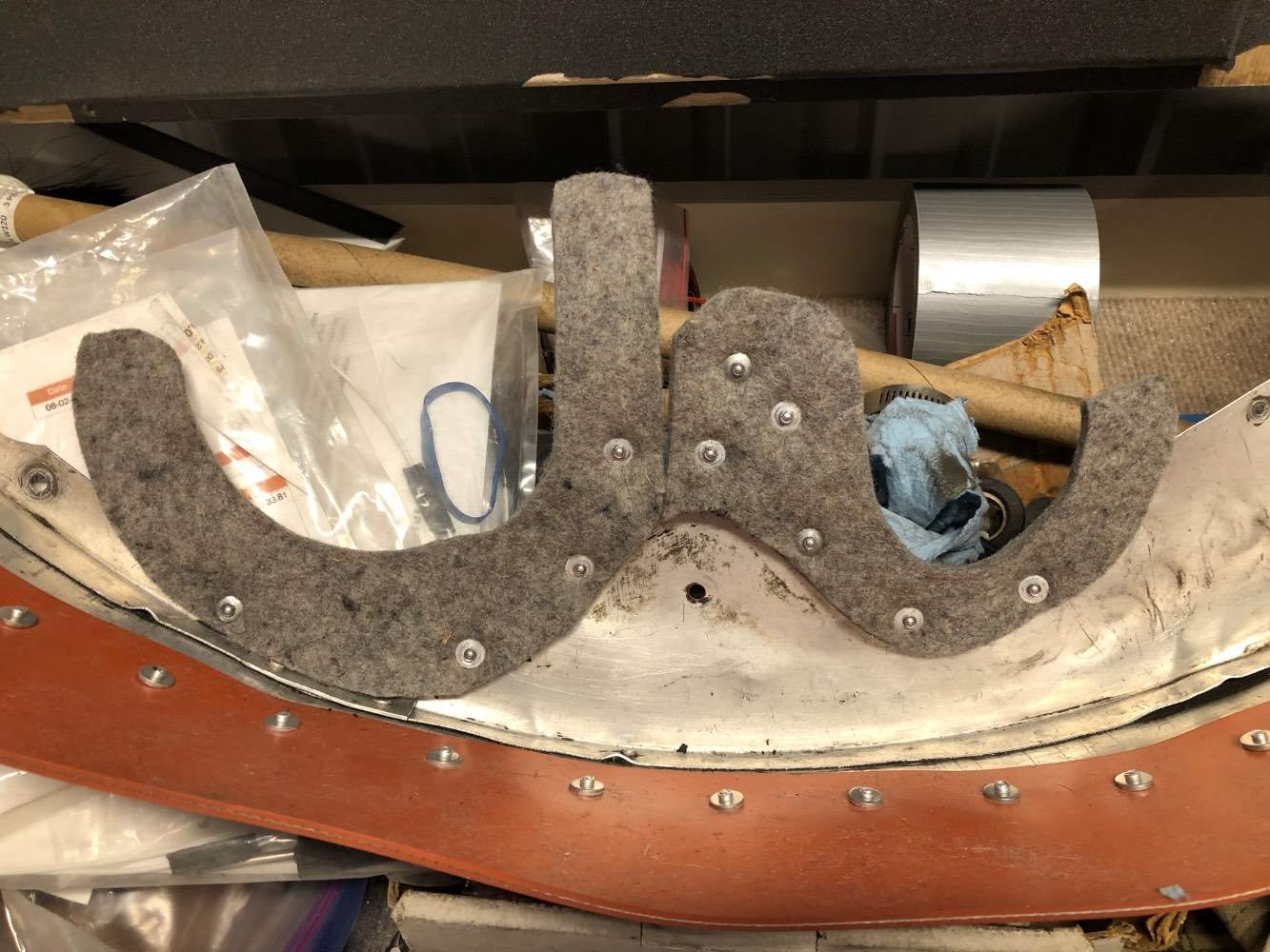
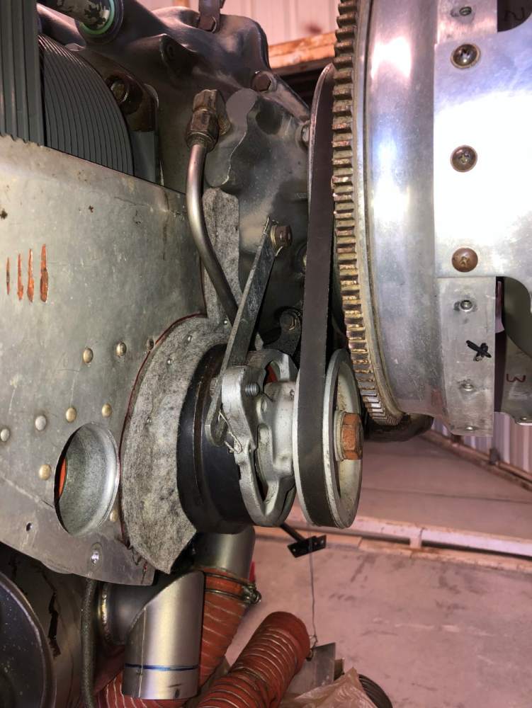
Plus 1 for felt… it just seems right on vintage birds.
-
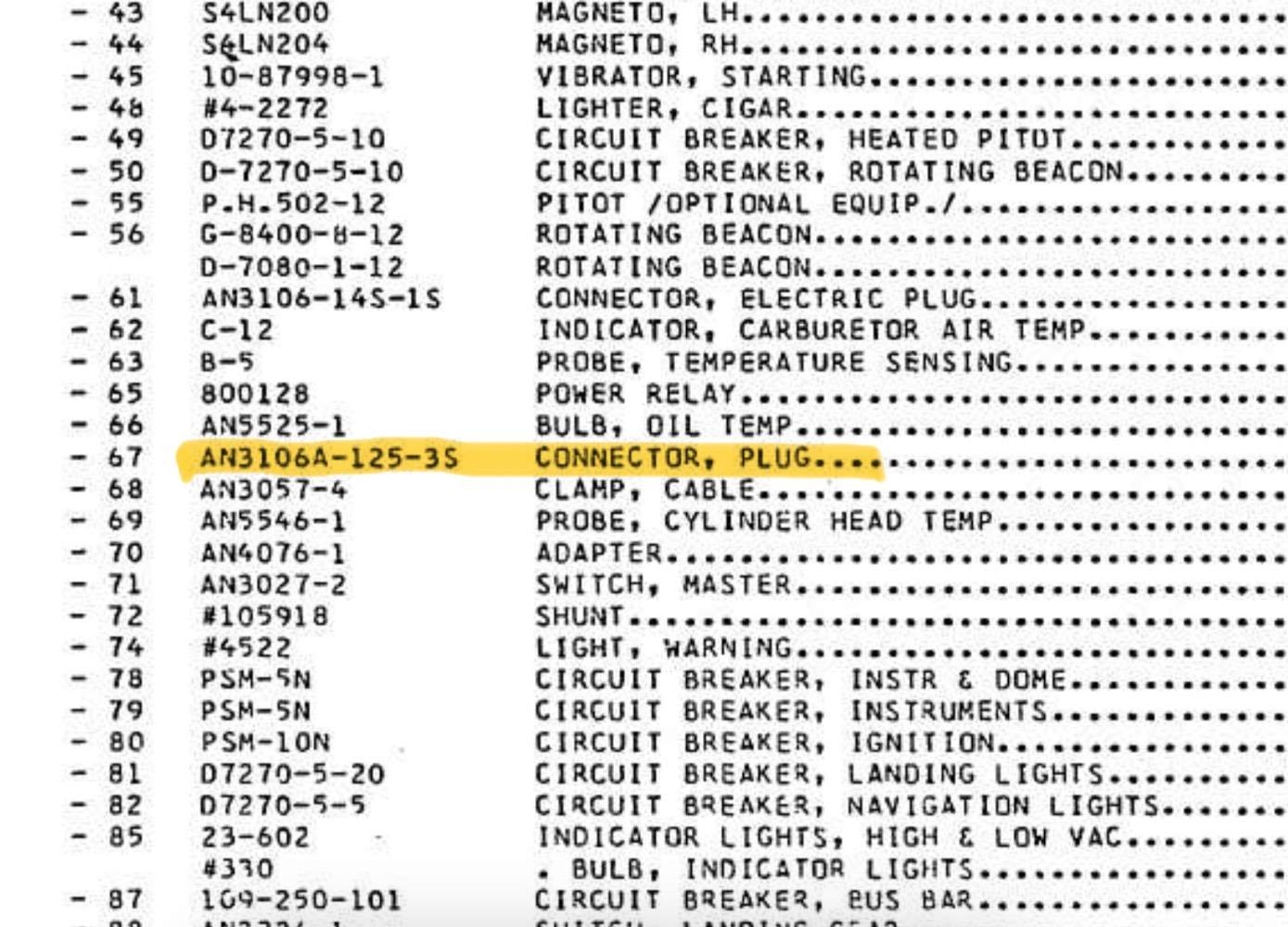
Try this… https://www.controller.com/parts/search?SearchType=Start&PartNumber=MS3106A-12S-3S The IPC electrical schematic shows the connector, but there’s a typo. It’s index 67, pn AN3106A-12S-3S, not -125-3S. Near as I could tell, that AN pn crosses to the MS pn shown on link to controller.com.
-
There are approved areas to add weight to the backplate and unapproved ways. Make sure your tech knows what’s what. There are a number of cracked backplate threads on MooneySpace. Dynamic prop balancing can be beneficial, but caution is advised.
-
There’s a suction screen for the oil pump in the oil sump. It should be checked every oil change, but is often overlooked by some. Lack of easy access might be the reason.
-
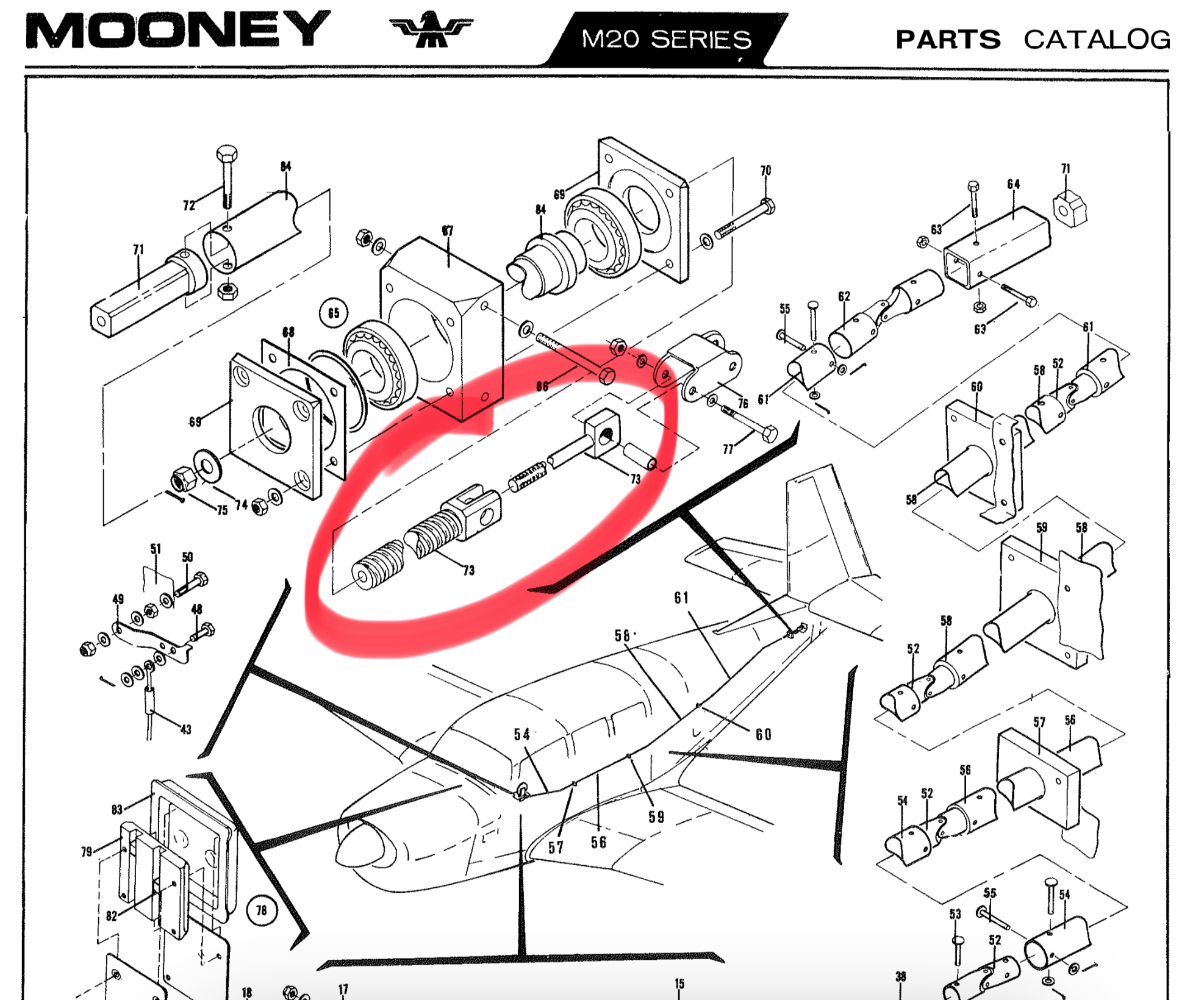
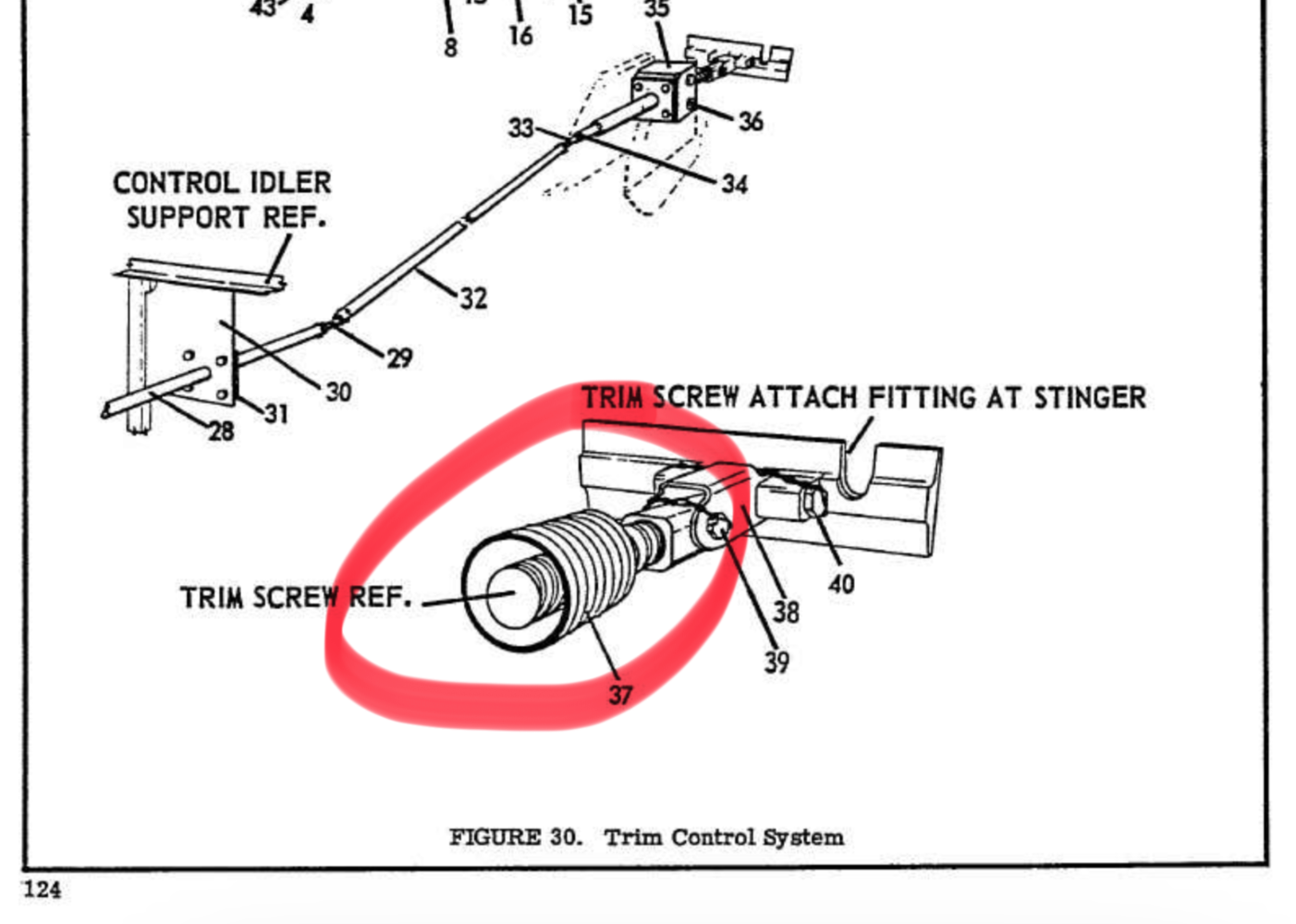
As Skip says, a short section of duct is sometimes used as the trim boot. But, I think the boot just makes it hard to clean, inspect, and lubricate the jackscrew. Unless you’re operating on grass/unimproved airport surfaces, you might consider not installing it. It should cleaned and lubed with new grease every annual whether there is a boot installed or not. Looking at the ‘68 IPC (Manual 205), the trim boot isn’t shown. Did Mooney dispense with it for a time? The previous year IPC (‘65-‘67) clearly shows the trim boot (duct) as pn 740087-3. LASAR also lists this pn… did they this one in stock?