All Activity
- Past hour
-

how to start without an electric fuel pump
Matthew P replied to bdavis3223's topic in Vintage Mooneys (pre-J models)
It’s for those individuals that have checklists. Lots of checklists. Hard copies and digital checklists on their iPad and phone BUT still can’t seem to follow their fugging checklist. But it’ also for those who do follow their checklist to let them know that during those critical phases of flight, where the checklist calls out for turning on the fuel pump, that their electrical fuel pump is/isn’t working and therefore, if it isn’t then you have no backup in the event the mechanical pump fails… -
When I went through this, the old original OEM part number relay was no longer available anywhere. There is some kind of advisory circular that allows A&Ps to install relays that don't match the part number, and arguably to install relays that are not TSO'd nor designed and intended for aircraft use. Someone in the distant past had used relays with NAPA auto parts stickers on them for my shore power, master, and starter relays. I discovered it when they started failing in interesting ways - the starter relay failed closed, resulting in the prop starting to move when you turned on the master. Modern TSO'd units should not fail like that. The answer is to use the TSO'd relays from Spruce. The mounting holes lined up just fine on mine, replacing an older style like the one in your photos. If not, you or your A&P might need to drill a couple new holes in your battery box, it just mounts with a couple of screws/bolts. Good time to order new mounting hardware while you're getting a shipment in from Spruce. Good luck.
-
What is the difference?
- Today
-

Garmin Yaw Damper - Weight & CG Implications
Oscar Avalle replied to oisiaa's topic in Vintage Mooneys (pre-J models)
yes. I did it and it helped -
Thanks!
-
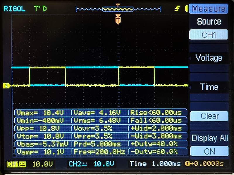
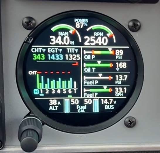
 I realize that this thread is over half a year old at this point but I am following up in case anyone else runs into this issue in the future. After nearly a year, we have finally isolated the root cause and have managed to resolve it. The bottom line is, the RPM signal being sent into the GEA24 sensor adapter is a pulse signal, and the duty cycle of said pulse signal must be greater than 50% in order for the GEA24 to process it properly at higher frequencies (i.e. RPMs). In other words, for every high-low period in the signal, the signal must spend more time in the "high" state than in "low." Since my last comment on this thread, we have tried installing magneto filters, rerouting cables to avoid high-noise areas, swapped the GEA24, swapped the GI275, and even replaced the P-lead interface with the UMA T1A3-4 tach drive sensor (approved for GI275 EIS since July 2025) all to no avail. We tried all sorts of experiments, including rotating the tach sensor with a drill (to simulate the engine rotating), powering the EIS (GEA24 and GI275) with a regulated power supply, powering just the RPM sensor with the power supply, and even testing a Hall-effect RPM gauge from Amazon and hooking it up to the UMA sensor to verify it played nicely with the Amazon gauge (it did, beyond an equivalent of 5000rpm). Eventually, we removed the GI275 and GEA24 from the airplane and constructed a basic wiring harness in the workshop. We have an oscilloscope and signal generator, so we had the signal generator feed into the RPM input port of the GEA24 to emulate a sensor (with the o-scope monitoring it). After playing around with the waveforms a little, we found that the duty cycle of the RPM signal directly impacts the EIS's ability to properly resolve a valid RPM reading at higher RPMs. Duty cycle | Max RPM before fail | Failure mode 15% 1200 rpm Fluctuates, then drops to 0 30% 2400 rpm Fluctuates, then drops to 0 50% 4000 rpm Fluctuates, then drops to 0 70% 4000 rpm Red X 85% 4000 rpm Red X The above data implies that in any case, the EIS (as configured for a Lycoming 6-cyl direct drive engine) only goes to 4000rpm before failing the RPM, likely by design (a Lycoming spinning at 4000rpm is ... bad). However, we can clearly see that the RPM performance drops sharply at duty cycles below 50%. As a side note, this may explain Garmin's position of the magneto being "at fault" regarding the erratic RPM readings on select EIS installations. I haven't had the opportunity to explore the magneto P-lead output on an oscilloscope but I suppose that different condensors/capacitors in the mag may directly impact the waveform, and in turn, the "duty cycle" despite it not necessarily being a clean-cut two-state pulse signal. Going back to the issue at hand, the UMA tach sensor, by construction, has a fixed duty cycle of 1/3, or 33%. Looking at the inside of the sensor reveals that the unit is nothing more than a wheel with a permanent magnet embedded somewhere in it, and this wheel rotates in close proximity to a PCB with a Hall sensor on it. Unfortunately this doesn't help the cause, but what can help is if the signal could be "conditioned" to an adequate format before being passed onto the GEA24. In this case, "inverting" the signal such that at 0V (low), the output is 12V (high) and vice versa, would effectively increase the duty cycle from 33% to 67% with minimal impact to the geometry of the waveform. There are several ways one can accomplish that, but ideally the "signal conditioning" circuit needs to (1) be reliable for long-term duty, (2) have fast switching characteristics, (3) be simple to construct (KISS method), and (4) be resilient to environmental variables like temperature and humidity. One possible method from this discussion is using a transistor, such as an IRF530 MOSFET, to drive the gate (or base in a BJT) to cause the transistor to conduct or cutoff between the drain (collector) and source (emitter): In the above circuit, the output signal is held at the MOSFET drain-to-source voltage. When the input is pulled high, the MOSFET starts conducting and effectively diverts the power passing through resistor R3 straight to ground. Thus the output voltage sees almost 0V. But when the input drops to a low voltage state, the MOSFET stops conducting and the output is virtually held at near 12V (assuming the GEA24 itself has a high impedance, which it does, so that only a minimal amount of current flows through it). I'm sure the real electrical engineers will hate me for the simplified explanation, but that's really the heart of the circuit. No circuit is perfect and the primary concern with this design is the MOSFET's ability to react quickly enough to sudden changes in the input signal. However, the IRF530 exhibits sufficient switching performance and testing with signals up to 13kHz (for the UMA T1A3-4 tach sensor which produces 2 pulses per engine revolution, that's equivalent to 390,000rpm) demonstrated that the circuit was still able to maintain a duty cycle of greater than 50% even with the imperfect rise/fall characteristics of the MOSFET. (Testing the circuit at near 13kHz. Yellow = input, blue = output) (Testing the circuit at 200Hz - equivalent to 6000 engine RPM. Yellow = input, blue = output) In the image above, the GI275 can be seen indicating RPM well above the 2200-2300rpm failure threshold I mentioned in my previous posts. In fact, this is near full power with the manifold pressure running well above ambient. Granted, the troubleshooting and testing here was all done with the UMA T1A3-4 sensor, which obviously works a bit differently than the magneto P-lead interface, so if anyone else is having issues and would like to keep the P-lead interface while implementing a solution, then a thorough review of the behavior and characteristics of the P-lead signal would be warranted.
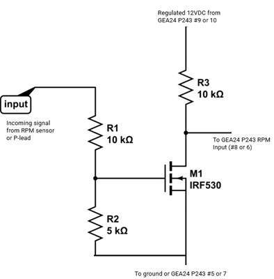

-

Looking for right side nav light clear screen M20D
47U replied to Heidi's topic in Vintage Mooneys (pre-J models)
https://www.aircraftspruce.com/catalog/elpages/clite.php?clickkey=328210 -
We’re still referencing the master relay, correct? Mx Manual 106, pg 9-129. Original installation by the factory was manufactured by Cutler Hammer, pn 6041-H-231. Several used examples on controller.com, and BAS lists them on their website, also. https://www.controller.com/parts/search?PartNumber=6041-H-231&SearchType=Start I think Spruce sells TSO’d replacements… if you’re looking for a new one.
-

how to start without an electric fuel pump
N201MKTurbo replied to bdavis3223's topic in Vintage Mooneys (pre-J models)
The pumps originally had steel vanes in a steel hub riding on a steel chamber. The rebuilt pumps have nylatron vanes. They don’t wear out the chamber or the hub. They will actually run dry for quite a while. -
When talking about no-back springs, it is important to distinguish between the two actuator manufacturers that Mooney used. There have been a number of documented failures of springs in GEC/Plessey actuators and I do not believe that no-back springs are available for these. The Eaton actuators (which confusingly were manufactured under several names) seem more robust. There was at least one (maybe two) documented failures many years ago causing Eaton to recall certain serial numbers which I believe is the source of the idea that there was a bad batch of springs. Probably some of these were never pulled and sent back to Eaton, but if they were going to fail, they'd certainly have done so by now. The spring is a wrap spring brake/clutch and it will wear in service. The chattering that Don Maxwell speaks of as a symptom of needing replacement is undoubtably caused by slippage of a worn spring. Outright failure is caused when the tangs on either end of the spring break jamming up the mechanism. I think this is a very, very unlikely event and I'm in no hurry to replace mine given the possibility of a maintenance-induced failure especially since there are now very few mechanics that have any significant experience working on these things. But, each owner will need to assess the risk and chose a course of action that they believe appropriate.
-
I just taped around them with masking tape before spraying.
-

how to start without an electric fuel pump
00-Negative replied to bdavis3223's topic in Vintage Mooneys (pre-J models)
Thanks for this profound statement. I have checklists. Lots of checklists. Hard copies and digital checklists on my iPad and phone. If following the checklist is the end-all solution, why did a boost -pump indicator light become standard equipment on late models? Your statement contributes absolutely nothing to this conversation. -David -
This Mooney has been sold!
-
Lovely!! For another flavor of Bay Area flying experience, may I suggest E55, 0Q3, and 1C9. Happy to fly formation!
-
@PT20J was right on the colors. None of the colors were right for what I wanted so I had a custom color made up. I put this project aside for a few weeks as I couldn't wear a respirator while my nose was healing post surgery. Structural repair to the overhead console is done and I've started to paint some parts. It's nice to see some progress but I wonder if I went too light on the color. We'll see when the whole interior is back in. Worst case, it will all come back out and get repainted. My interior had more damage than I realized but it's all fixable, it just takes time. How is the wemac assembly removed? The wemac seat is glued to the backside of the overhead console and I'm afraid that if I cut through it, I'll end up doing damage on the finish side of the overhead console. I'd like to avoid doing that but they need to come out so that I can paint the area properly. The upholsterer is working his magic on the seats, I expect to have them back this week. I need to order the carpet; I got the burn certificate for it today. The hardest part is finding someone locally to serge the carpet as it seems everyone does binding instead.
-

Based on the G100UL fuel leak thread what's your position?
gabez replied to gabez's topic in General Mooney Talk
I just got the data from the county. KWVI sells, on average, 11,600 gallons of 100LL per month -
I'm looking for a part number/replacement for this puppy: pretty difficult for me to find it in the svc/maintenance manual but I'm wondering if a Sky-Tec Sts-M12 Battery/Master Solenoid By Lamar would suffice, other than how it would be mounted?


-
https://www.seaerospace.com/faqs/314#:~:text=Will the KX-155A%2F165A,A radios include additional features.
-
Garmin Yaw Damper - Weight & CG Implications
Ragsf15e replied to oisiaa's topic in Vintage Mooneys (pre-J models)
Do Mooney’s wag their tail much? No. Is it noticeable, yes. Surprisingly noticeable and steadying. In the PA46 I fly it’s damn near Required equipment and that’s a “straight tail single” too. -
to my best recollection factory parts biz used to be $5-6M per year, everything revolves around that number, a lot of the know how resides with the few people left in Kerrville, hope Lasar makes a go of it
-
On the job training is the best learning. If you learn, you get paid; if you screw up, you're no longer employed.
-
Running 17.5 GPH 1590 TIT. I tried to run it LOP however TIT at that FF would be at 1650 and loss of speed would be almost 15KTS.
-
I find that even in the GPS environment that radio is way cool!
-
A 70 year old German machinist who taught me everything about materials, machining, engineering, CNC programming (even though he couldn't use a computer), how to hunt, how to be a man, never to back down from a fight but still remain humble, and when I should not make a sarcastic comment! Mike is still kicking today, over 90 years old. They simply do not make people like him any more. All hail the old timers!
-

Garmin Yaw Damper - Weight & CG Implications
LANCECASPER replied to oisiaa's topic in Vintage Mooneys (pre-J models)
For years the only option for rudder trim was this: http://www.aerotriminc.com/id2.html Not a huge difference in price just to add the YD on the Garmin now.