Mooney-Shiner
-
Posts
299 -
Joined
-
Last visited
Content Type
Profiles
Forums
Blogs
Gallery
Downloads
Events
Store
Everything posted by Mooney-Shiner
-
 I own 20F in Tampa, let me know if you want to check it out
 -
How do you like it? Have you used it yet? I want to make sure that it does a good job in pulverizing the Corrosion X, which is pretty heavy. The more it's pulverized/atomized the less you have to worry about getting a direct hit on every surface. Well-atomized fog will settle on all surfaces of an individual compartment (should at least).
-
Boost pump connection
Mooney-Shiner replied to Mooney-Shiner's topic in Vintage Mooneys (pre-J models)
Thank you! I will look up AC 43.13-1b. Any suggestions on the good ground on plane's underbelly? -
Boost pump connection
Mooney-Shiner replied to Mooney-Shiner's topic in Vintage Mooneys (pre-J models)
Kortopates, Unlike the detailed IPCs of Encore, the Beatles-era IPCs of As-Fs provide rather marginal info of some areas of aircraft. As mentioned above, the rigging of boost pump is one of those areas. -
Boost pump connection
Mooney-Shiner replied to Mooney-Shiner's topic in Vintage Mooneys (pre-J models)
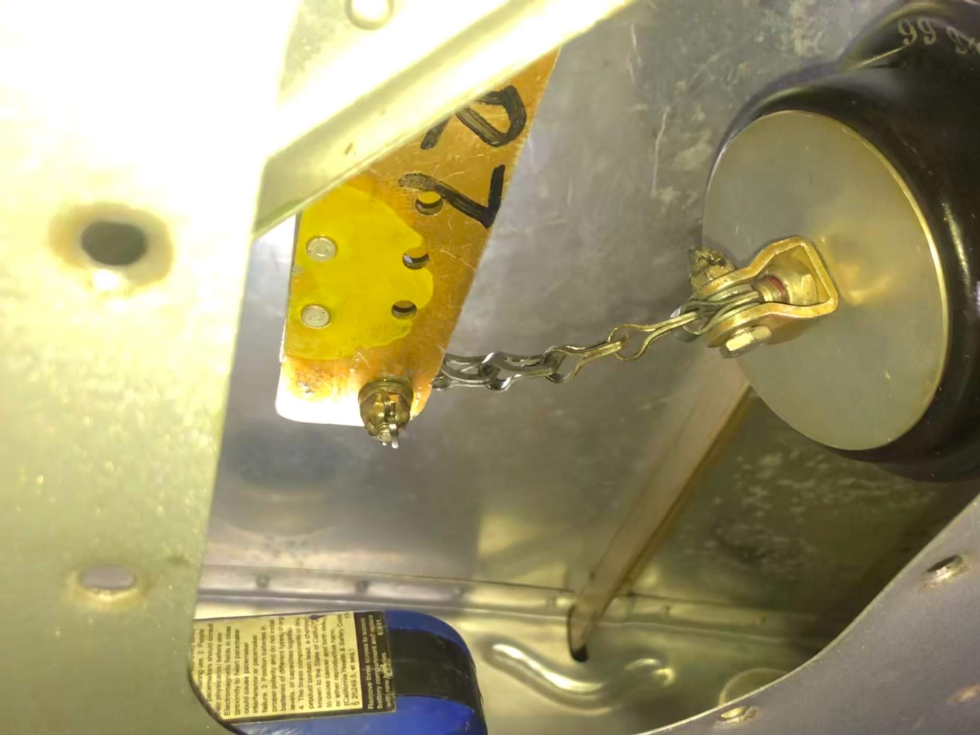
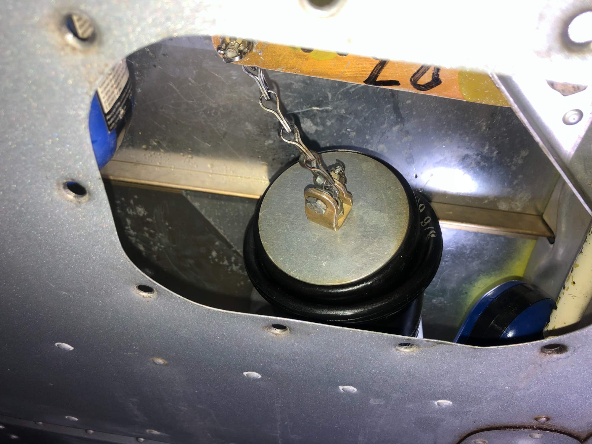
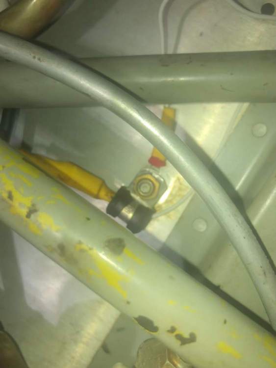
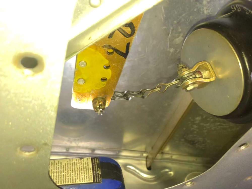
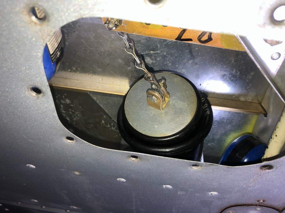
I can see that you attachment has AN365 self-locking nut, which make better sense to me than my own set up. I don't like the fact that my nut is not self-locking, which is not helping with accidental detachment due to the frame vibration. Or maybe I'm just overthinking this... -
Boost pump connection
Mooney-Shiner replied to Mooney-Shiner's topic in Vintage Mooneys (pre-J models)
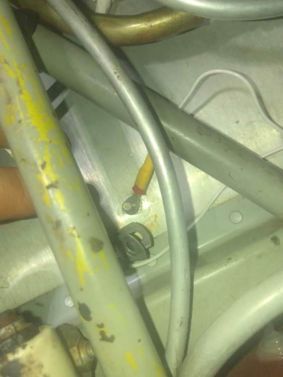
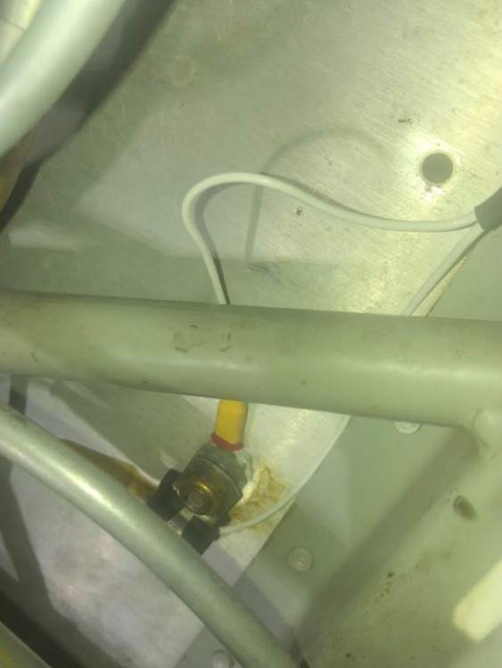
Yep, thats why I hoped that there was some manual reference to proper install. My rationale by attaching the negative eye terminal of the pump under the clamp to attach it as close to the main body as possible to provide a solid ground. Additionally, if it is under the clamp and two nuts - this provided less likely possibility for the terminal to wobble out of attachment leaving me without the boost pump mid-flight. But yeah, I wish there was a better dedicated attachment location. -
Happy weekend, everyone. I had to send my electrical boost pump (Dukes 1499-00-19) to Aeromotors for the rebuild. While I reinstalling the rebuilt pump on the plane the same way it was previously installed, I realized how flimsy the installation of the ground wire was to the body of the airplane. I tried to reference the Parts Catalog and Service Manual to see where and how exactly the ground wire should be attached and what nut and washer should be used. But to my surprise there was no detailed the schematic on how the ground wire should be mounted, despite the fact that I view this part as a major airworthiness item. So I did my best to secure the ground wire to the floorboard best of my ability (as seen in the photos). Did anyone else ran into the same issue previously?
-
PC Leveler reinstall
Mooney-Shiner replied to Mooney-Shiner's topic in Vintage Mooneys (pre-J models)
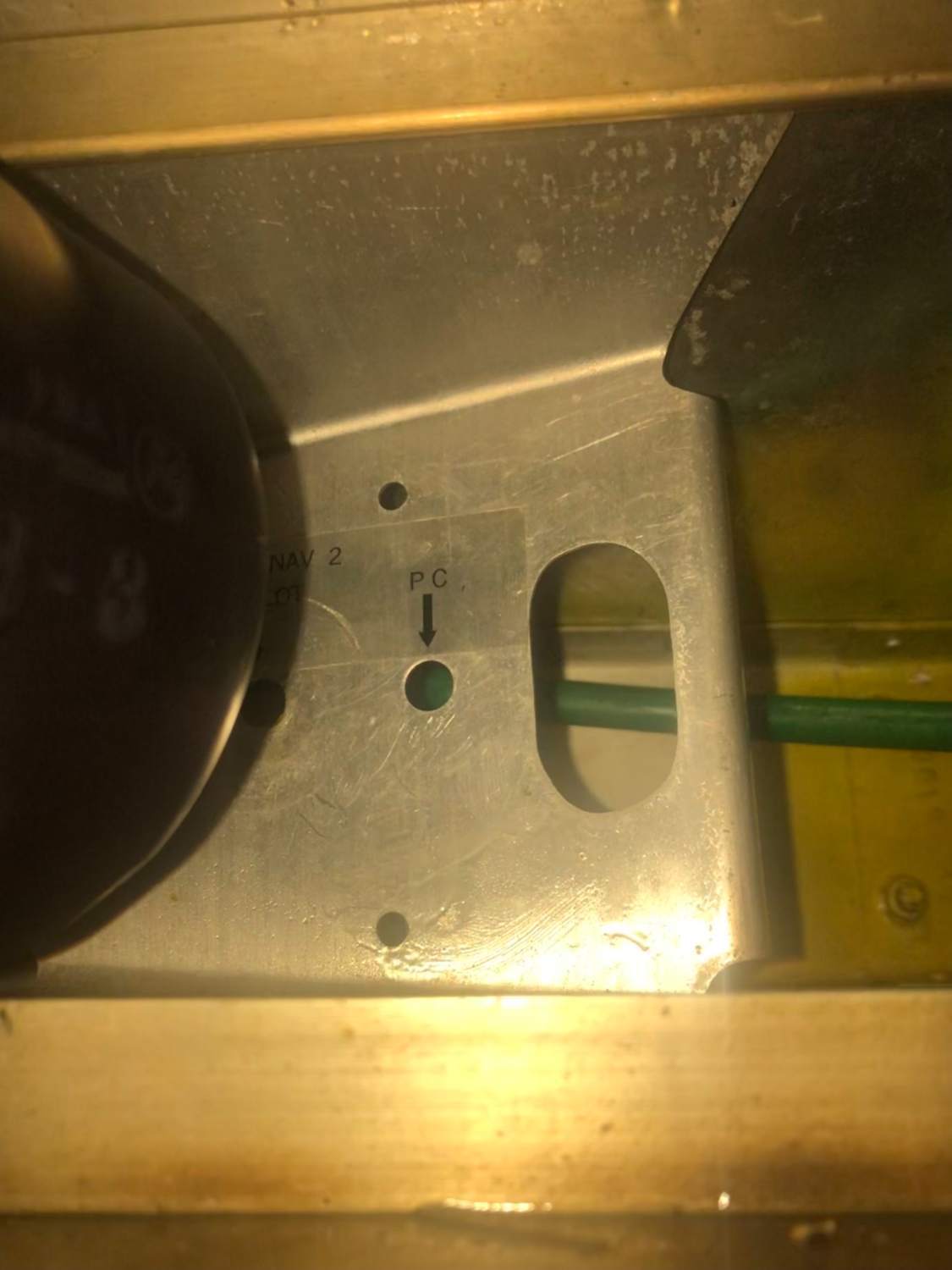
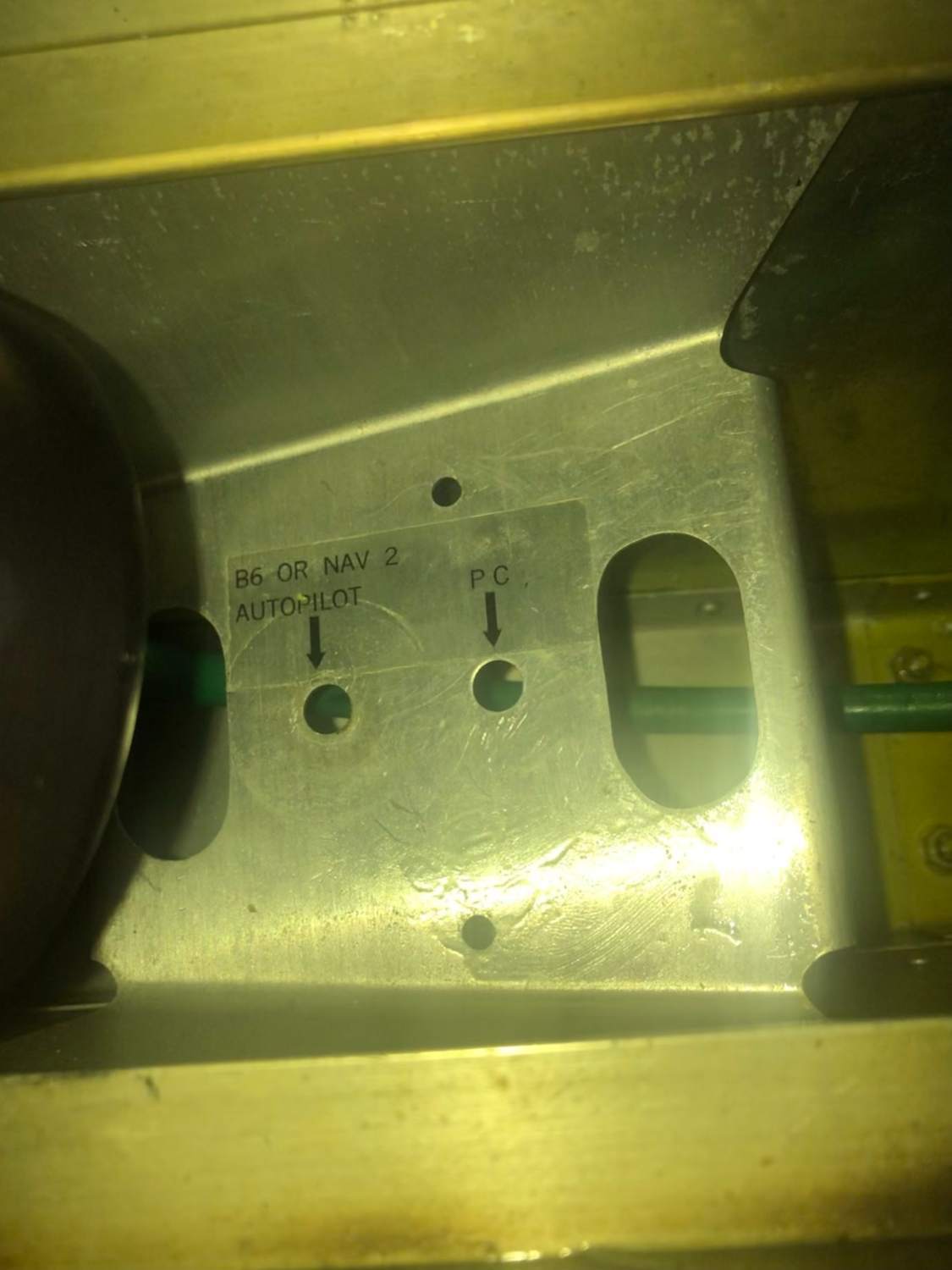
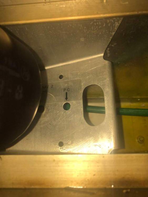
Awesome! This is exactly the right stuff, I just don't get why the Brittain prescribes to use the outboard hole which is marked "B6 or Nav2 Autopilot." I guess this would be a question to Cecilia at Brittain. Thank you, TakAir -
Happy weekend everyone! I finally got around to replacing the torn boots on the aileron PC servos. When I was removing the the servos, I realized that they were attached to the wrong holes on the servo bracket. See the photos. The bracket has the the outboard hole marked as "B6 or Nav2 Autopilot" and the inboard hole marker as "PC." The is also an outboard and inboard opening for vacuum line routing. Originally, my boots were attached to the outer holes "B6." My plan is to remount them to "PC" inboard holes as I believe that PC describes these servos properly. I was wondering if anyone has any experience in PC Leveler system mounting? I looked through the Parts Catalog and Service and Maint Manual, but can't find any reference to this particular mounting area beyond just a simply drawing. I really don't want to rig it in the way where the servos will interfere with a full range of motion of ailerons.

-
Mooney Rigging tools In Tampa area
Mooney-Shiner replied to Mooney-Shiner's topic in Vintage Mooneys (pre-J models)
Mooney Space wins again! I would like to thank everyone for volunteering to help! The project was completed and the tool set is enroute via insured shipping to Vance who graciously agreed to help the brother Mooniac out! -
Mooney Rigging tools In Tampa area
Mooney-Shiner replied to Mooney-Shiner's topic in Vintage Mooneys (pre-J models)
Vance, I'm going thru it right now with my IA. I will PM you and will cover all the shipping fees off course -
Hello, team! Time to do some gear rigging, but Lasar is out of stock on the main gear rigging tool. So here is the type of post that periodically popping out on the Mooney Space. I was wondering if anyone owns a set of front and main gear rigging tools in Tampa area. I will gladly pay you a rental fee and the cost of your tools as a collateral deposit, in addition to paying for your time. I only need these tools for about a week to get through my annual. Alternatively, if you are out of the area, I will also gladly pay the shipping and for your time. Thank you, everyone. Yuriy
-
Not Mooney related, but disconnected throttle related. This family of four had their throttle disconnected mid-flight and engine automatically going into full power. They were able to land manipulating mixture. The video and explanation is pretty good. https://www.youtube.com/watch?v=q-Y99df66rY
-
Ah, makes sense now. For whatever reason, I thought my IPC was dedicated F Model pub. But I'm a better man now.
-
Hey, guys, just wanted to post for posterity sake about this discrepancy. I was looking to gather some info about the engine shock mounts replacement. According to our IPC, my 67F takes J-7402-1 (made by Lord Aviation). But according to Lord's guide, the appropriate P/N is J-9613-12. I contacted the vendor about this correct P/N and the shelf life of their cushions and this is what I got back: " Hi Yuriy, Thank you for contacting Parker LORD. According to our internal reference guide, we also call out four of the J-9613-12 engine mounting kits for the Mooney M20F 1967 model. Looking at the component part numbers that come in the J-9613-12 kit compared to those included in the J-7402-1 kit, it appears that the Mooney manual made an error. They have the components listed that correspond to the J-9613-12 mounts as our application guide notes, but yet list the J-7402-1 kit number. For verification, I have included the components of the J-9613-12 and J-7402-1 kits below. J-9613-12 Assembly: J-7763-1 sandwich mount J-9612-8 sandwich mount J-7766-9 spacer J-7402-1 Assembly: J-7401-1 sandwich mounts J-7588-1 spacer These mounts do have a shelf life. The recommended shelf life of the J-9613-12 mounts is 5 years from the date of manufacture (cure date printed on the mounts). However, this limit only applies to the time period when the mounts are in their new, unused condition prior to being installed. Once they are installed, on-condition inspections take over and shelf life no longer applies. We do not specify a set in service life for our GA engine mounts for it varies with application, environment, flight patterns etc. If you need any additional assistance, please let us know. Thanks, Emily" I'm not sure if anyone ran into these issues yet, but I want to give you a heads up.

-
Checking Cam Lobe Condition
Mooney-Shiner replied to corn_flake's topic in Vintage Mooneys (pre-J models)
Thank you for posting this. I would like to develop this a little more. 1. Is there a SI or SB on exact procedure? 2. Besides all intake/exhaust comparison, is there an absolute number that we are looking for on the measurements? -
Really cool! Are you in Tallahassee?
-
Learned a lot from you!
-
Need Dukes Fuel Pump p/n 1499-00-21 for '69 M20C
Mooney-Shiner replied to TexMooney's topic in Vintage Mooneys (pre-J models)
I second on Aeromotors! I just sent mine in and had 1 week turnaround. Easy to work with them and for $450 they totally overhauled my boost pump. I also called them several times to consult on reinstallation. -
First, use masking tape to protect the paint around panels. Use drywall knife and soft rubber mallet to open access panels. Don't do up and down motions or you will bend the metal. Do side to side and in and out motion with light tapping with rubber mallet. The key for me was to use shop-vac to the vent in order to find exact location of leaks. This is what this method look like: Patch the leaks with Flamemaster CS-3204 Class B-2 Integral Fuel Tank Sealant. Run another shop-vac test to ensure that you got all the leaks. Apply CS 3600 top protective coat on the new tank sealant. Re-seal the access panels with CS-3330B-2 low adhesion sealant for easy access. For references, check Mooney SM manual pages 7-5 thru 7-11. Also this thread helped me A LOT:
-
Great work! I just did some patching and it is really tedious. But I used the shop-vac to the air-vent to find leaks. Its pretty cool idea with 12V pump! Just make sure that the vacuum is not too strong and it will not collapse the sealant.
-
Any Brittain servos?
-
Alan, Do you have aileron brittain servos? Mine are torn. How about left yoke clock?
-
Do you have any servos that are either marked with part number 20424-0-1 or part number 2983? Mine have boots torn
-
Parting out a 63 C model...
Mooney-Shiner replied to Alan Fox's topic in Avionics / Parts Classifieds
PC system?