PT20J
-
Posts
10,275 -
Joined
-
Last visited
-
Days Won
234
Content Type
Profiles
Forums
Blogs
Gallery
Downloads
Events
Store
Everything posted by PT20J
-
The Mooney is as spin resistant as any other normal category airplane. During certification, it had to meet CAR 3 spin requirement of recovering from a one turn spin in one and a half additional turns. It generally takes two turns for a spin to become fully developed. So, if you initiate a prompt recovery control application, it will recover. This assumes you are reasonably coordinated when it breaks. If very uncoordinated - especially in a skid - most airplanes will snap over into a spin very rapidly. If you want to investigate this, do it in an aerobatic airplane with an aerobatic instructor. People seem to fear stalls in a Mooney. I suspect it is because the Mooney wing has a more abrupt stall break than trainers. Also, some tend to drop a wing at the break which is disconcerting. This is corrected with rudder, but that is a learned response and the natural tendency is to try to use the ailerons which makes matters worse. During factory flight test, the stall strips on the wings were positioned to produce a nearly wings level stall (CAR 3 actually permits up to a 15 deg roll if recovery is delayed for one second). But over time, hangar rash, repairs, small rigging errors, etc. can cause a particular airplane to drop a wing at the stall. Mooney stalls are not a problem if you stay within what was demonstrated at certification: coordinated flight, deceleration at the rate of one mph per second until either stall or the elevator is fully deflected. If you want to investigate more aggressive situations, do it in an airplane designed for spins.
-
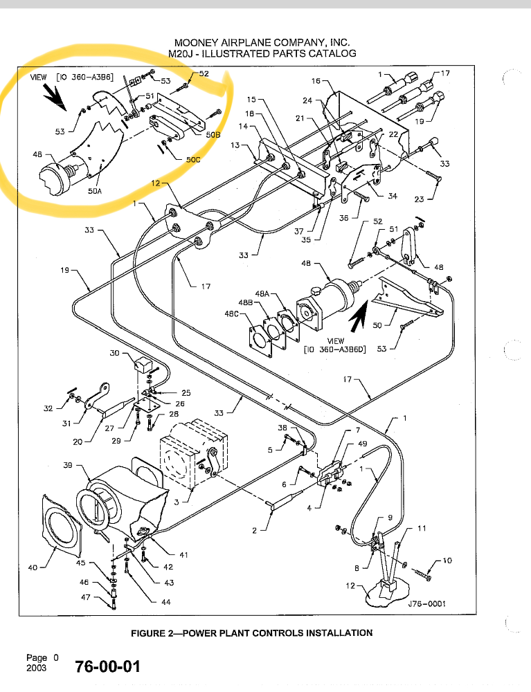
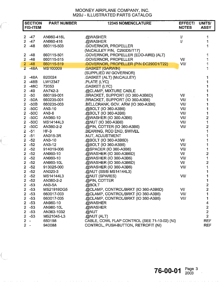
The prop control has more range of movement than necessary for normal operation to allow full control of the blade angle between the high and low pitch stops. Normally, the control is fairly far advanced because we operate at an rpm that is within a few hundred rpm of redline. But, in the event of an engine failure, pulling the prop control all the way back will drive the blades to the high pitch stop greatly reducing drag and increasing the glide distance.
-
As long as you can make redline rpm just before liftoff and can adjust the prop to 2400-2600 rpm for cruise, then everything is fine. Most use the cruise rpm that is smoothest and will generate desired power when combined with available manifold pressure. Personally, I take off and climb at 2700 rpm and cruise at 2500 rpm unless above 10,000’ when I use 2600 rpm to get more power from the reduced manifold pressure available at full throttle.
-
Are you saying that the control only moves a hair width from 2700 rpm to 2500 rpm? If so that’s not correct.
-
I use Aeroshell 7, same as aileron guide blocks and trim screws (fore and aft).
-
A leak test is supposed to be performed whenever the static system is opened per 91.411.
-
Naw, they don’t pass through grommets and are not in the center of the fuselage. You can see the rudder and elevator push pull tubes in the video on either side of the central trim torque tube.
-
Trim torque tube.

-
I’ve always used ABS cement which is MEK, acetone, and ABS resin. It’s black and in cases where I wanted white, I just melted white Legos in MEK.
-
Another source. https://www.brownaircraft.com/aircraft-wind-lacing-s/264.htm Also, Bruce Jaeger used to sell it. I don’t know if the new owners still do. https://www.jaegeraviation.com
-
I don't know about previous models, but according to the IPC, Mooney put teflon tape on the M20Js from S/N 24-0001 through 24-0810 and heat shrink tubing thereafter. The OP's appears to have the heat shrink. On mine, the oil from the grease allowed the heat shrink to slide out of position. Cleaning the tube with solvent, moving the tubing back into place and hitting it with a heat gun tightened it up. The additional protection may not be necessary, but the grommet is nylon which is a pretty hard material rubbing on the relatively soft aluminum torque tube, so it might be a good idea.
-
No, fuel quantity is part of the EIS. You would connect the fuel senders to whatever engine monitor you are using instead.
-
Remove the rubber hanger, then remove the three bolts at the ball joint. Put some C5-A anti seize on the ball joint when reassembling. It is easiest if you install the rear bolt/spring first when reassembling the ball joint. The springs lose tension from heat. Aircraft Spruce sells them if you need to replace them. Make a new rubber hangar - they crack eventually from the heat, so you might as well replace it now. There is a recent thread on MS about options for the hanger.
-
So how does autoland work? Do computers “feel”?
-
Has anyone had experience with Houston Tank Specialists? https://htsllc.net
-
If you look in the back of the service manual you should find the part number for the switch. It is probably still available. Tri-Flow is a light oil with Teflon. Teflon and oil are both insulators so it’s hard to see how that would be good to spray into an electrical component. Once a switch wears through the precious metal plated on the contacts, the base metal beneath will oxidize. Contact cleaner will sometimes temporarily remove the oxidation, but the switch should be replaced for a permanent fix.
-
1. You have ample physical evidence that the high temps are real. Use the well probe -- it will be the most accurate. 2. Intake leaks are most noticeable at low power, but if that cylinder is running leaner than the others it should drop out well before the others when leaning aggressively. 3. The rate of the temperature rise on takeoff together with the damage caused to the first cylinder could indicate preignition. Since this happened on two cylinders in the same position, it would have to caused by something you did not change such as the plugs or the magnetos. It's possible one of the plugs has a cracked insulator. When one of the insulators cracked on my engine it would do something similar at high power. I would replace the plugs in that cylinder with new ones. 4. I would borescope the new cylinder to determine if there has been any damage.
-
I just bought a set from Kerry McIntyre https://www.knr-inc.com/products-list.html
-
Well, that explains the tracers when I go missed in the Spit. Was certain it was a TOGA button.
-
Give the man a watch.
-

Electric gear failed to retract m20f
PT20J replied to mpilot's topic in Vintage Mooneys (pre-J models)
Call Frank Crawford at the factory. -
Electric gear failed to retract m20f
PT20J replied to mpilot's topic in Vintage Mooneys (pre-J models)
If it doesn't go up it is most likely either the safety switch (squat or airspeed) or the up limit switch or the up relay. Sometimes the plunger on the up limit switch sticks. I don't know how it works on an F, but on a J you will get a gear warning horn if you put the gear switch up and the safety switch is closed. EDIT: You didn't say which breaker related to the gear doesn't work, but that would be the first thing I would check, because it sounds like the breaker suffered some sort of mechanical failure and it may not be making contact internally. -
I don't believe that this is the intended use of the OBS Mode Select discrete input. Although connecting a TOGA button to it and pressing it during an approach should cause the navigator to unsuspend and sequence to the MAHP, pressing TOGA at other times (like before takeoff) would cause the OBS mode to toggle which is not what you would want. Anyway, the only drawing I see in the installation manual utilizing this input shows connecting it to a Mid-Continent MD41 Series Annunciation Control Unit which includes a button labelled OBS (not TOGA). I believe this drawing, coupled with the fact that there is no mention of a TOGA (or Go Around as Garmin calls it) button in the installation manual or the pilot's guide pretty clearly indicates the intended purpose of the OBS mode select input. MD41-140X_141X_im.pdf
-
There is a VOR-A approach at KPAE with a DME arc that is near and dear to the local DPEs.