

PT20J
-
Posts
10,166 -
Joined
-
Last visited
-
Days Won
231
Content Type
Profiles
Forums
Blogs
Gallery
Downloads
Events
Store
Everything posted by PT20J
-
Can you provide more detail about the symptoms you are experiencing? There are people here with a lot of experience with these actuators.
-
Go fast switch?
-
Lycoming switched to AvStar some years back so if it was new, rebuilt, or overhauled by Lycoming in the last 10 years or so, it will have an AvStar servo.
-
Some electrical components are listed in the IPC but the most reliable way to find them is to look at the end of the Service Manual for the electrical equipment chart that matches your serial number and schematic and locate the reference designator from the schematic in the chart to determine the component part number. In this case the reference designator is D1.

-
You have to go into Config. It's on the EIS page.
-
The F2 terminal should be grounded. The F1 terminal goes to the voltage regulator. The diode should be connected between F1 and ground with the cathode (the end with the band) connected to F1. (The Mooney schematic is incorrect). This is a flyback diode that absorbs EMF from the field when the current is suddenly removed which sometimes causes the field CB to pop when the ALT switch is turned off. I'm not sure why you would have two diodes.
-
Set it to record flight time. That agrees with FAR part 1 “Time in Service” for maintenance records and will give you lower total time than any “engine running time” setting.
-
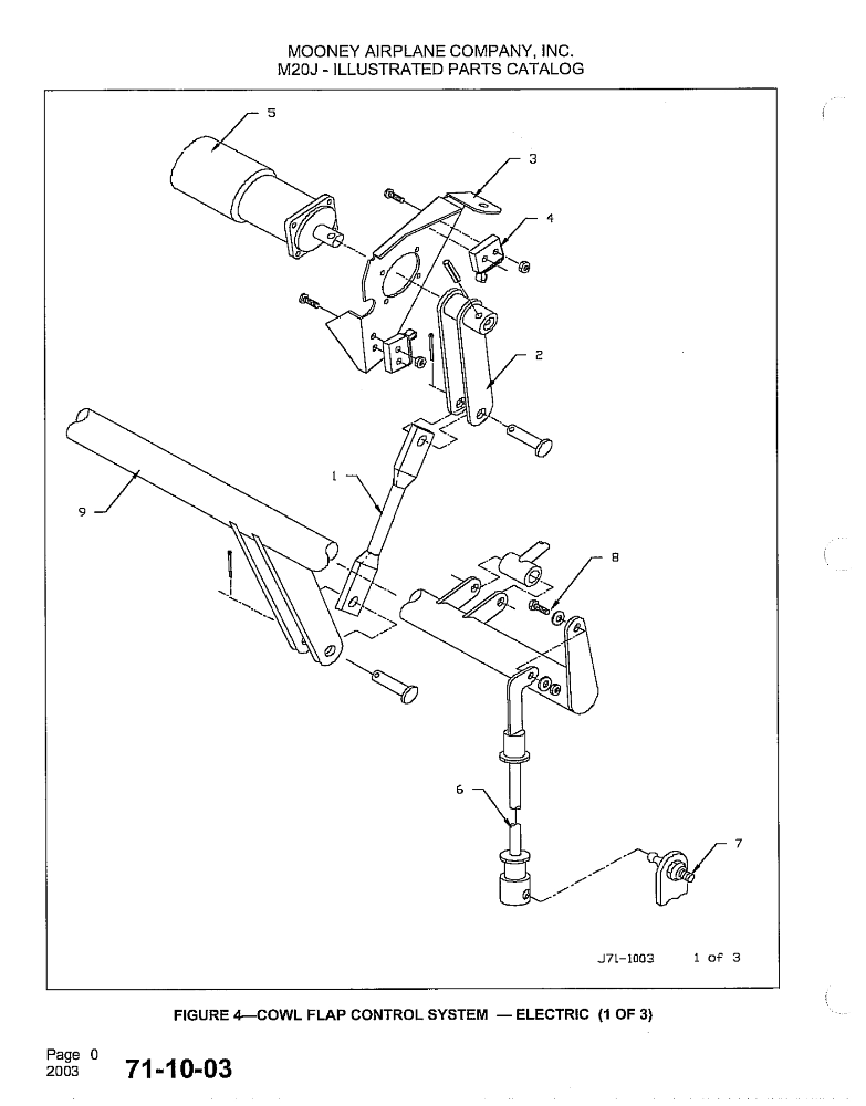
The IPC calls for two roll pins and I believe there are two 90 degrees apart, but I've never had to replace them. @kortopates will know. The solder connections to the top microswitch in the picture look a little funky. Maybe that's the problem.
-
The schematics are actually part of the Service and Maintenance manual. Chapter 91 at the back of the manual has the part numbers for electrical components. So you find the schematic for your serial number and look up the reference designator for the part you want and then go to the section in chapter 91 for your serial number and find the part number that corresponds to the reference designator. Most will be standard electrical components available from any number of online electrical parts suppliers.
-
Is this a crack in the exhaust?

-
Maybe this picture from the IPC will help. Looks like the roll pins sheared. So it will be necessary to figure out why. Probably a problem with a limit switch.
-
Has anyone used Bruce’s lighter travel covers for the occasional night out?
-
The o-rings leak with 5606, too. I just had to rebuild my master cylinders last year. I've replaced piston o-rings in both sides. So, be sure to put in a new o-ring when you take the piston out of the caliper to clean it. If you do eventually have a master cylinder leak, it's a good time to replace the brake hoses.
-
5606 does that with age. Many have switched to a newer synthetic MIL-PRF-83282 fluid such as Royco 782 which doesn't seem to do this.
-
Maybe you are right. I was just referencing the IPC.
-
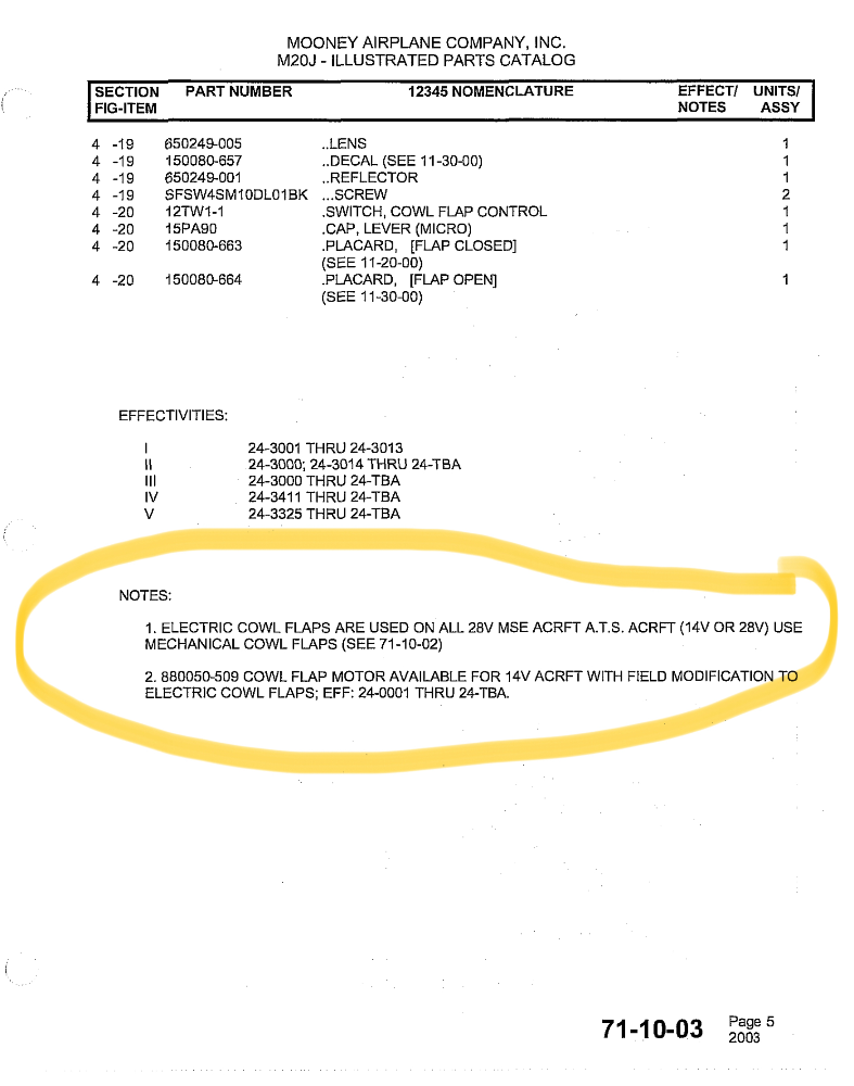
Mooney changed from manual to electric when it changed the electrical system to 28V. It did offer a 14V retrofit kit to optionally add them to older models.
-
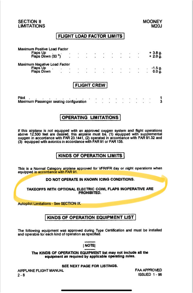
The rub is that there is a prohibition against taking off with inoperative electric cowl flaps in the POH/AFM Limitations and FAR 91.9 prohibits operating contrary to a limitation.
-
If the motor runs but the flaps don’t move and you can move the flaps by hand, it has to be something broken mechanically. Check the roll pin.
-

Water in the belly-where to start checking for leaks...
PT20J replied to N9405V's topic in General Mooney Talk
I’d pull the inside side panels and check the windows for leaks. If they leak, water runs down between the skins and the trim panels into the belly. That’s how the tubular structures rust because the water doesn’t show inside. Pilot’s window is the first thing to check. -
Thirty-five years ago I was an engineering manager at a telecom equipment manufacturer. The CEO decided to fire the VP of Manufacturing and gave the job to the VP of Engineering - my boss. In turn, my boss anointed me warehouse supervisor. Some weeks earlier, I had ordered a birthday present for my wife and had it sent to the company so she wouldn't know about it. UPS said it was delivered, but the warehouse crew swore they never received it. Now, I was suddenly and unexpectedly their boss. I got everyone together on the warehouse floor and said that the first order of business was to find my wife's birthday present. After the shock wore off, it only took fifteen minutes to find it where it had fallen behind some other boxes.
-
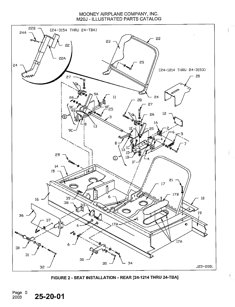
There are two designs for the seat back frames as shown in the upper left of the drawing. The later ones move the back further into the baggage compartment providing more rear seat room. The bottom is just a cushion that rests on the plastic pan. Your seats have to be somewhere. I’d go searching for them myself.
-
2.0" dia x 22.0" long. The one between the muffler shroud and the firewall valve is 2.50" dia x 33" long. I ordered SCEET (double wall silicone with finished ends) from @Gee Bee Aeroproducts and it will last longer than the engine.
-
Need replacement ASI for M20J 2900GW
PT20J replied to fatlasercat's topic in Modern Mooney Discussion
Yes, the ASI serial number matches mine. It’s Mooney part number 820308-535 which according to the IPC was used on SN 24-3201, 24-3218 on. The IPC lists several part numbers of ASI for various M20J serial numbers. EDIT. I see yours is a -525. -
Dukes Motor Overhaul. Where? Who? What?
PT20J replied to Echo's topic in Vintage Mooneys (pre-J models)
The biggest failure mechanism isn't the actuator -- it's the pilot. Just look at all the gear ups. And, it's not that people are stupid or careless -- a lot of very experienced pilots have gotten distracted and missed the gear. I used to be in a club in San Jose that had a manual gear M20C that managed to get bellied in twice. -
Need replacement ASI for M20J 2900GW
PT20J replied to fatlasercat's topic in Modern Mooney Discussion
Check with Skylar Thody at Skyman Avionics 541-604-9573. I think he still has mine from my 1994 M20J MSE. It was working fine when removed for the G3X installation.


