

PT20J
-
Posts
10,328 -
Joined
-
Last visited
-
Days Won
237
Content Type
Profiles
Forums
Blogs
Gallery
Downloads
Events
Store
Everything posted by PT20J
-
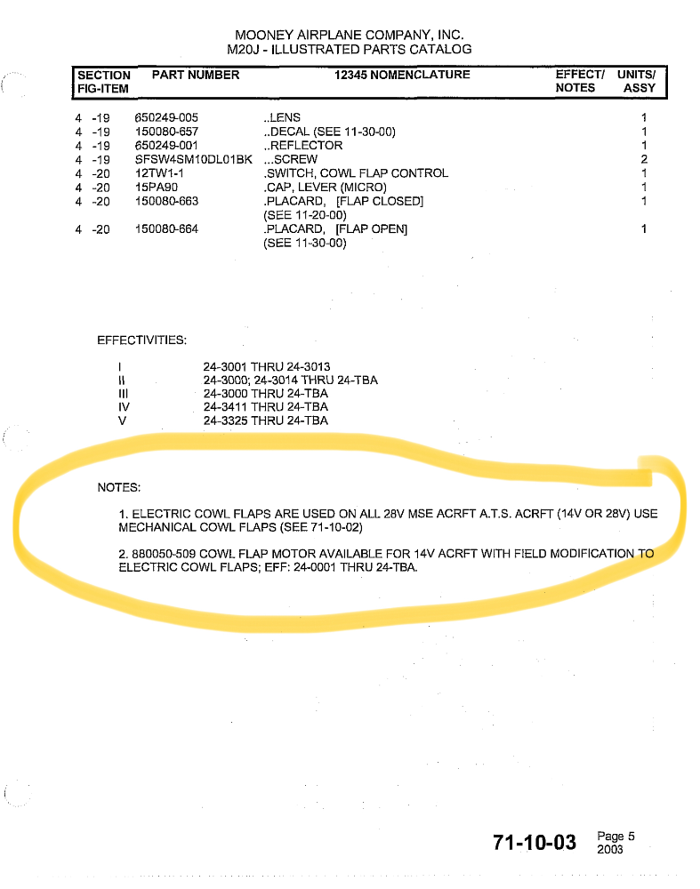
Maybe you are right. I was just referencing the IPC.
-
Mooney changed from manual to electric when it changed the electrical system to 28V. It did offer a 14V retrofit kit to optionally add them to older models.
-
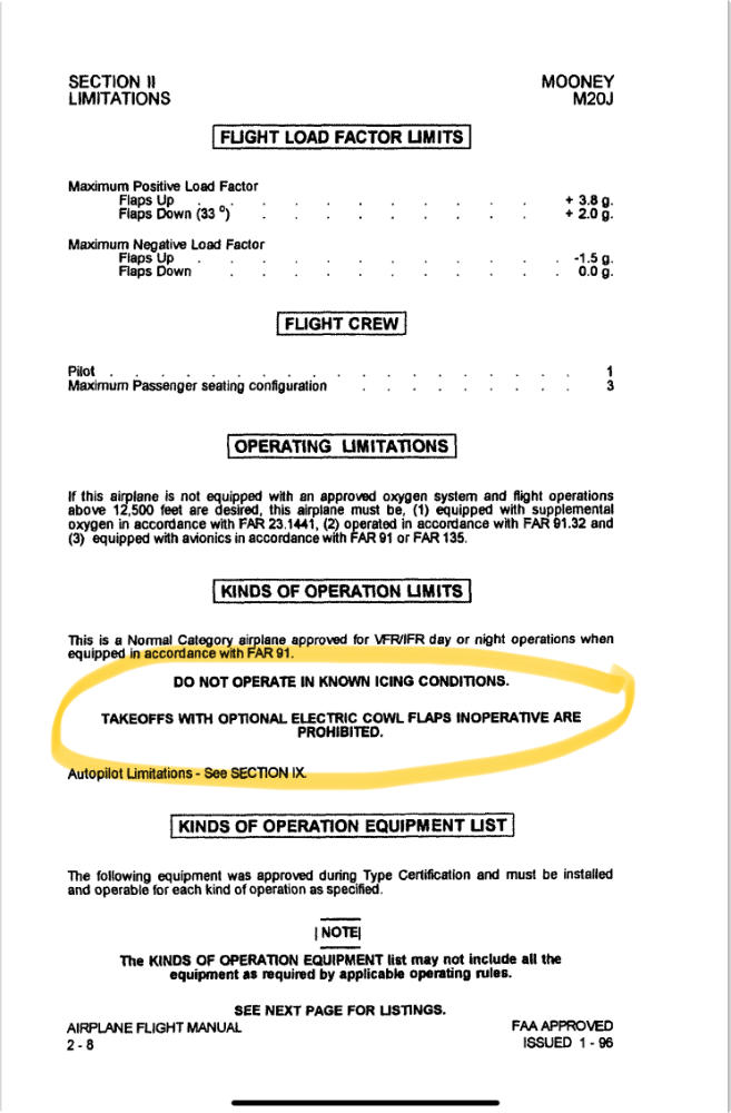
The rub is that there is a prohibition against taking off with inoperative electric cowl flaps in the POH/AFM Limitations and FAR 91.9 prohibits operating contrary to a limitation.
-
If the motor runs but the flaps don’t move and you can move the flaps by hand, it has to be something broken mechanically. Check the roll pin.
-

Water in the belly-where to start checking for leaks...
PT20J replied to N9405V's topic in General Mooney Talk
I’d pull the inside side panels and check the windows for leaks. If they leak, water runs down between the skins and the trim panels into the belly. That’s how the tubular structures rust because the water doesn’t show inside. Pilot’s window is the first thing to check. -
Thirty-five years ago I was an engineering manager at a telecom equipment manufacturer. The CEO decided to fire the VP of Manufacturing and gave the job to the VP of Engineering - my boss. In turn, my boss anointed me warehouse supervisor. Some weeks earlier, I had ordered a birthday present for my wife and had it sent to the company so she wouldn't know about it. UPS said it was delivered, but the warehouse crew swore they never received it. Now, I was suddenly and unexpectedly their boss. I got everyone together on the warehouse floor and said that the first order of business was to find my wife's birthday present. After the shock wore off, it only took fifteen minutes to find it where it had fallen behind some other boxes.
-
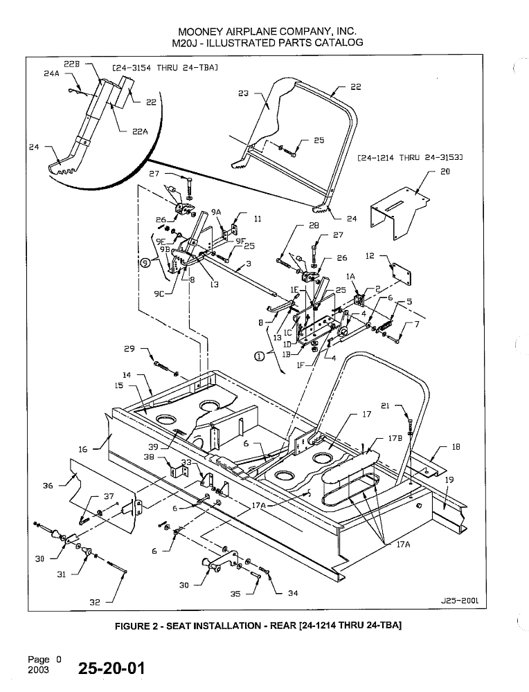
There are two designs for the seat back frames as shown in the upper left of the drawing. The later ones move the back further into the baggage compartment providing more rear seat room. The bottom is just a cushion that rests on the plastic pan. Your seats have to be somewhere. I’d go searching for them myself.
-
2.0" dia x 22.0" long. The one between the muffler shroud and the firewall valve is 2.50" dia x 33" long. I ordered SCEET (double wall silicone with finished ends) from @Gee Bee Aeroproducts and it will last longer than the engine.
-
Need replacement ASI for M20J 2900GW
PT20J replied to fatlasercat's topic in Modern Mooney Discussion
Yes, the ASI serial number matches mine. It’s Mooney part number 820308-535 which according to the IPC was used on SN 24-3201, 24-3218 on. The IPC lists several part numbers of ASI for various M20J serial numbers. EDIT. I see yours is a -525. -
Dukes Motor Overhaul. Where? Who? What?
PT20J replied to Echo's topic in Vintage Mooneys (pre-J models)
The biggest failure mechanism isn't the actuator -- it's the pilot. Just look at all the gear ups. And, it's not that people are stupid or careless -- a lot of very experienced pilots have gotten distracted and missed the gear. I used to be in a club in San Jose that had a manual gear M20C that managed to get bellied in twice. -
Need replacement ASI for M20J 2900GW
PT20J replied to fatlasercat's topic in Modern Mooney Discussion
Check with Skylar Thody at Skyman Avionics 541-604-9573. I think he still has mine from my 1994 M20J MSE. It was working fine when removed for the G3X installation. -
22 V open circuit voltage would be a 0 charge state. In a M20J, there are overhead lights connected to switches in the overhead. These are wired directly to the battery and will deplete it when left on. If the battery is dead, it might show 0 V in the airplane if the switch to the lights is still on. After removing the battery it might recover a bit which might be why it showed higher voltage outside the airplane. The test @MikeOH suggested would confirm. You can try charging it and then performing a capacity test to check the battery’s health. However, as others have said, Gill sealed batteries don’t seem to last long and your best bet might be to replace it with a Concorde.
-
Makes sense since the GFC software resides and executes in the GI 275. The GI 275log file should show what errors occured.
-
If it doesn't clear with a power cycle, and all the connections are sound, a trip to a Garmin dealer is the solution.
-
G3X / GTN / GTX 345 Traffic Voice Alerts
PT20J replied to PT20J's topic in Avionics/Panel Discussion
Garmin did fix this some software releases back, so current software gives you audible traffic bearing and elevation callouts. I never bothered connecting ForeFlight audio to the panel. I just have ForeFlight Bluetooth connected to the G3X to transfer flight plans. -
Dukes Motor Overhaul. Where? Who? What?
PT20J replied to Echo's topic in Vintage Mooneys (pre-J models)
It's a problem with equipment that has been out of production for half a century. There may not be any spare parts around anymore for wear items like brushes unless someone has some new/old stock sitting on a shelf somewhere. -
I got one of these. Used 2 layers of blocks.

-
How many people lost an Alternator/Voltage Regulator in flight?
PT20J replied to Yetti's topic in General Mooney Talk
My panel draws about 6A @ 28V. My G3 LED landing and taxI lights (2 ea.) draw 6A if all are turned on. LED bulbs draw less current than incandescents, but they still can drain reserve from the battery and they would be the first load I’d shed. (Like many, I leave them on all the time to increase my visibility to other airplanes. I think it works because opposing traffic frequently reports me in sight before I see them). -
How many people lost an Alternator/Voltage Regulator in flight?
PT20J replied to Yetti's topic in General Mooney Talk
I don’t have a photo, but the 6 AWG output wire is well supported with clamps and I cable tied the other wires securely to that. I also eliminated the fuse holder connected to the AUX terminal for a tachometer option that was never installed on my airplane. -
Mustang geared up, and many more...
PT20J replied to philiplane's topic in Mooney Safety & Accident Discussion
The Mooney landing gear locks down with over center linkages. This means that any force applied to a wheel in the direction of retraction will just lock it down harder. But, any force applied in the opposite direction (for example, towing from the nose wheel, or the main gear on the outside of a turn or swerve) will tend to straighten the over center linkage. The gear still cannot fold up because the linkage prevents that, but it is important that the linkage returns to the over center position when the load is removed or it can fold. The bungees are there to ensure that the linkage snaps back over center when the load is removed. If the bungees are rigged too loose, I suppose it is possible for a gear to fold up if the conditions are just right. -
Possible Oil leak on a new engine? M20E 1975
PT20J replied to ighazali's topic in Vintage Mooneys (pre-J models)
@Gee Bee Aeroproducts makes some that have a reinforcing fabric layer sandwiched in between two layers of silicone so that they hold their shape better under pressure. I had a rocker cover leak and it turned out to be a pinhole defect in the cover itself. -
Same basic type of mechanism, but the gear actuator is much beefier.
-
Not all over, and not in snow. But I got it once on the windshield flying south over San Mateo CA at about 5000 in the clouds. I could put my finger on the inside of the windshield and move the glow around. It was pretty, and pretty eerie.
-
How many people lost an Alternator/Voltage Regulator in flight?
PT20J replied to Yetti's topic in General Mooney Talk
It seems from various posts here that the most common failure mode is a broken field wire. I have reinforced the wiring to the alternator to reduce vibration stress and I inspect it every time the cowling is off. Second most common problem seems to be voltage regulators. Mooney used different regulators over the years. I have a suspicion that the newer regulators may be more reliable, but I don’t know for sure. My 1994 MSE has a small Mooney brand. No idea who made it for Mooney, but it’s about the size of a Zeftronics. -
M20E Backup Electrical System
PT20J replied to AH64Bennett's topic in Vintage Mooneys (pre-J models)
Check the actual current draw and the Ahr capacity of your battery. My similar panel will run for 2 hrs on the ships battery.


