-
Posts
1,547 -
Joined
-
Last visited
-
Days Won
6
Content Type
Profiles
Forums
Blogs
Gallery
Downloads
Events
Store
Everything posted by Vance Harral
-
I never heard any banging or clicking noises operating the ailerons by hand or via the yoke during a normal preflight. The only way I could get them to click was by manually twisting the linkages back and forth in the belly at annual, as seen in the video. For most of the time we've owned the airplane, doing this would only get the aileron links "very close" to the gear retraction torque tube. I could still slide a sheet of paper in there, and I didn't observe any wear marks, so we didn't bother with the SB. It only started actually touching a couple of years ago. We would have done the work at the 2020 annual, but could not get the spacer kit at the time. In summary, I don't think this is an OMG-we're-going-to-die maintenance item, just something to keep an eye on from year to year.
-
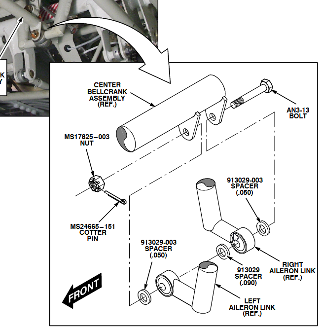
Thanks to N201MKTurbo and EricJ for the pointers. The A&P who looked it over said it was kosher, but I'm always learning. With regard to what's in the manual, the original parts manual shows one washer under the self-locking nut, but no washer under the bolt head. The diagram in SB M20-289A shows no washers at all. I can see how the bolt head and nut could wear on the U-bracket. But again, there's basically no torque or fore/aft load on the bolt and nut, all the forces are in shear.
-
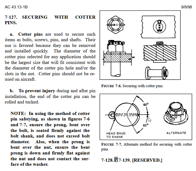
I see what you're saying, only one of the two cotter pin shanks is actually locking the nut. But the SB doesn't mention additional washers, so it's unclear to me if that's "authorized" (maybe it's kosher under generic 43-13 principles). In any case, I'm not particularly concerned about it. There is no meaningful torquing load on the nut that would cause it to break a castle point or to pop the cotter pin, even with only one shank holding against the nut.
-
We paid $220 for the kit at our local Mooney MSC (Arapahoe Aero) a few months ago - just now getting around to installing it. LASAR also has the kit listed for $236: https://lasar.com/service-bulletin-kits/service-bulletin-kit-289-m20-289-000 Not very expensive in aviation dollars, I guess, but a little frustrating. The kit contains an AN bolt, castle nut, and cotter pin that you can get from Spruce for about two bucks. The "magic" is the three specially-sized washers that exactly fill the gap where the rod ends are captured by the U-bracket.
-
We elected not to bother with an external GPS antenna installation when we recently had a G5 ADI installed, even though it's our primary ADI. GPS data is fed to our G5 from an external source (GTN 650 in our case, but any WAAS GPS will do). Our rationale was that the G5 does *not* become unusable if it loses GPS signal. The availability of GPS data allows the G5 to perform exceptionally good drift correction, but without that data, it can still provide "pretty good" drift correction using air data (pitot/static) to drive the drift correction filter. The shops we talked to about the installation all claimed it was very rare for them to install the GPS antenna and configure the G5 to use its internal GPS. Not saying you should just do what everyone else is doing, but it seems most shops and customers are coming to the same conclusion we did.
-

What is this stuff in my gascolator?
Vance Harral replied to Vance Harral's topic in General Mooney Talk
Pulled the fuel servo inlet screen today and found more junk. Cleaned and flushed with solvent. Still no smoking gun as to exactly what's causing this. -

What is this stuff in my gascolator?
Vance Harral replied to Vance Harral's topic in General Mooney Talk
15-20 *inch* pounds is the torque spec on the gascolator. It's very light. Use caution, I broke my fuel selector last year after mis-understanding the torque spec, and finding a replacement was a saga. You can undo the rod on the nose gear door. Or, if your airplane is more workhorse than beauty queen, a long-shaft phillips screwdriver with a bit of flex in the shaft, and a willingness to bend and rub on the gear door during the deed, can also get the job done. We don't necessarily replace the gasket every year, I will re-use it a second year if it appears to be in good shape. LASAR does indeed sell the gasket and fancy washer, but be aware they sold me a faulty gasket last year. I'm not saying it's their fault, necessarily - they just stock parts from Mooney. But it was definitely bad. You can read about it here: https://mooneyspace.com/topic/34307-fuel-selector-woes/?do=findComment&comment=584949 -

Yoke set screw: to Loctite or not
Vance Harral replied to Vance Harral's topic in General Mooney Talk
Concur with Robert. After our original loctite debacle, I'm skeptical of any "works great" story that doesn't include a positive PIREP on the ability to remove it at the next inspection. -
The especially eagle-eyed will note that at some point in the history of our airplane, the bolt and nut in the "before" video were installed backward. The bolt head is supposed to be aft, and the nut forward. There is a slight downward tilt of the mechanism from aft to forward, so with the bolt head aft, the bolt would theoretically stay in place if the nut were to fall off. In the backward installation, if the nut were to come off, the bolt would be more likely to work completely loose. That's the aviation "standard", though I don't put much faith in it - I'd rather be sure nuts don't come off!
-
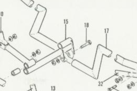
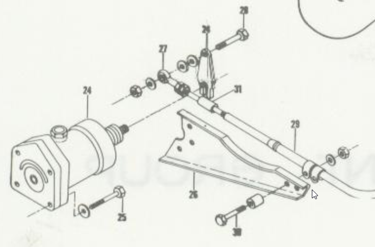
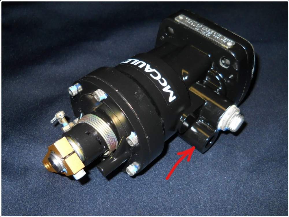
Guessing you've already decided on your course of action, but I finally got a fresh look at our McCauley governor and I remembered why grinding the case was necessary. In many governor installations, the part of the accessory case that receives the governor has threaded studs installed. The governor slides over the studs, then you install nuts to fasten the governor tight to the accessory case. That is not the way it's installed in Mooneys, however. Instead, the governor is installed with MS20074-05-14 bolts, which are a little over 1.5" long - see item #25 in the parts manual pic below. The design of the McCauley governor is such that it is not possible to slide a 1.5" bolt through one of the four mounting holes, because of a protrusion on the case which I've marked with a red arrow below (I believe this is a pickup port for a prop synchronizer system). So to install the McCauley governor, you must either swap the mounting bolts for threaded studs (unclear to me if this is "legal"), or grind the case protrusion just enough to slide the bolt in.
-
For those of you not familiar with SB M20-289A, or those who just haven't gotten around to performing it, here are before/after videos on our 1976 M20F. We've been aware of the issue for a while now, but it was only within the last year that our original installation actually began to have the clearance problem described in the S.B. Ordered the kit from Mooney, and installing the new spacers does make a significant difference. Before: After: Video link https://youtu.be/MqET4p8saMI
-

Yoke set screw: to Loctite or not
Vance Harral replied to Vance Harral's topic in General Mooney Talk
Follow-up: we decided to try this "second set screw acting as jam nut" idea. Installed a second screw in each yoke about 3 weeks ago, seems to be holding nicely so far. -

What is this stuff in my gascolator?
Vance Harral replied to Vance Harral's topic in General Mooney Talk
We checked this today. It sinks like a stone, which makes it all the more mysterious that it was on top of the screen rather than the bottom. The shop IA got tied up today and hasn't really had a chance to look closely and consult. It'll probably be Monday before he can really dig into it. -

What is this stuff in my gascolator?
Vance Harral replied to Vance Harral's topic in General Mooney Talk
Ideas that it may have something to do with the boost pump are interesting. We have the "new" Weldon pump, but it was installed over 15 years ago, and has about 1000 hours of service (a lot less time actually in operation, of course). -

What is this stuff in my gascolator?
Vance Harral replied to Vance Harral's topic in General Mooney Talk
We did have a patch job done in March of 2020. This stuff wasn't in the gascolator in April of 2020 at last year's annual. If the shop that did the patch job left shop rag material in the tank, it took more than two months to migrate to the gascolator. But perhaps that's not implausible. -

What is this stuff in my gascolator?
Vance Harral replied to Vance Harral's topic in General Mooney Talk
Don't know. But we saved it, I will check tomorrow. The plan is to look. Hoping not to have to drain the tanks to do, so, but can do that if necessary. -

What is this stuff in my gascolator?
Vance Harral replied to Vance Harral's topic in General Mooney Talk
I was the last person to lay hands on the screen a year ago, and no I did not not clean it with a shop rag. I'll work with the shop tomorrow to check the fuel servo finger screen, thanks for the tip. Checking it again after a few hours' operation is definitely on the agenda. -

What is this stuff in my gascolator?
Vance Harral replied to Vance Harral's topic in General Mooney Talk
I'm about 95% sure our airplane does not have that post-boost-pump screen, because we have a replacement Weldon boost pump. But I'll double-check tomorrow. Thanks for the tip, any and all ideas are welcome. -

What is this stuff in my gascolator?
Vance Harral replied to Vance Harral's topic in General Mooney Talk
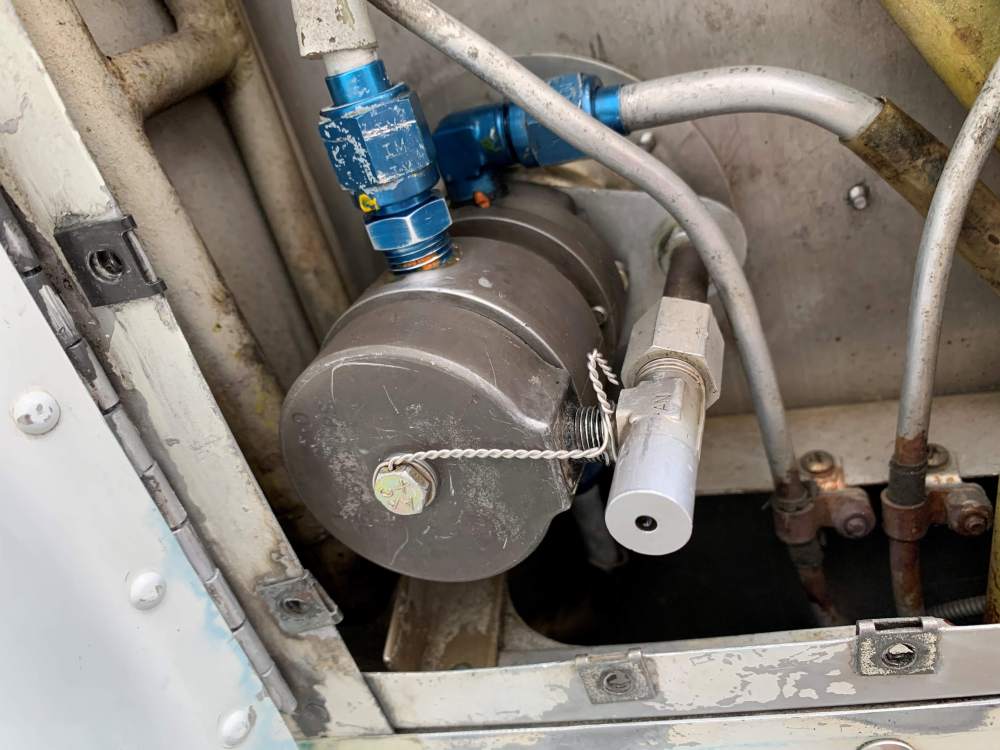
It's certainly possible I misunderstand how the fuel selector works, but I don't think so. Below are a couple of photos of the Dukes fuel selector/gascolator in our airplane. These are taken from underneath the airplane, looking up. The feed lines from the tanks are at the top (i.e. at the "back" of these photos), while the line to the boost pump is at the bottom (the "front" of these photos). The screen is beneath the level of all the supply and feed lines. With the bowl removed, when the fuel selector is moved from OFF to LEFT/RIGHT, fuel drains through the center of the unit, not through the screen. It comes out the four small holes in the center post that you see in the photo, and fills the bowl. It must then flow up through the screen, to exit out the boost pump line, and on to the engine driven pump. The arrangement appears to work like a P-trap on a sink. The gunk was entirely located above the screen (or "behind" the screen relative to these photos). That's the engine side, not the tank side. -

What is this stuff in my gascolator?
Vance Harral replied to Vance Harral's topic in General Mooney Talk
The idea that it came from a fuel provider is an interesting one. That would be a one-off event, consistent with finding junk in the screen, but none when draining the tanks or pumping through the electric pump. Still, I'm mystified by the fact the material is on the downstream side of the screen, opposite side from the fuel tanks. If the contaminant came from or passed through the fuel tanks, I would have expected to find it on the upstream side of the screen. Might be a good idea to get a look at the pickup screens in the fuel tanks in any case. Any way to do that safely without completely gdraining the tanks? I have a cheap endoscope I can feed down there. I don't mind if doing so winds up killing the endoscope, but I wouldn't want material sloughing off the endoscope to contaminate the fuel or cause other problems. I might try draining some fuel into a bucket and putting the scope in there first as an experiment. -
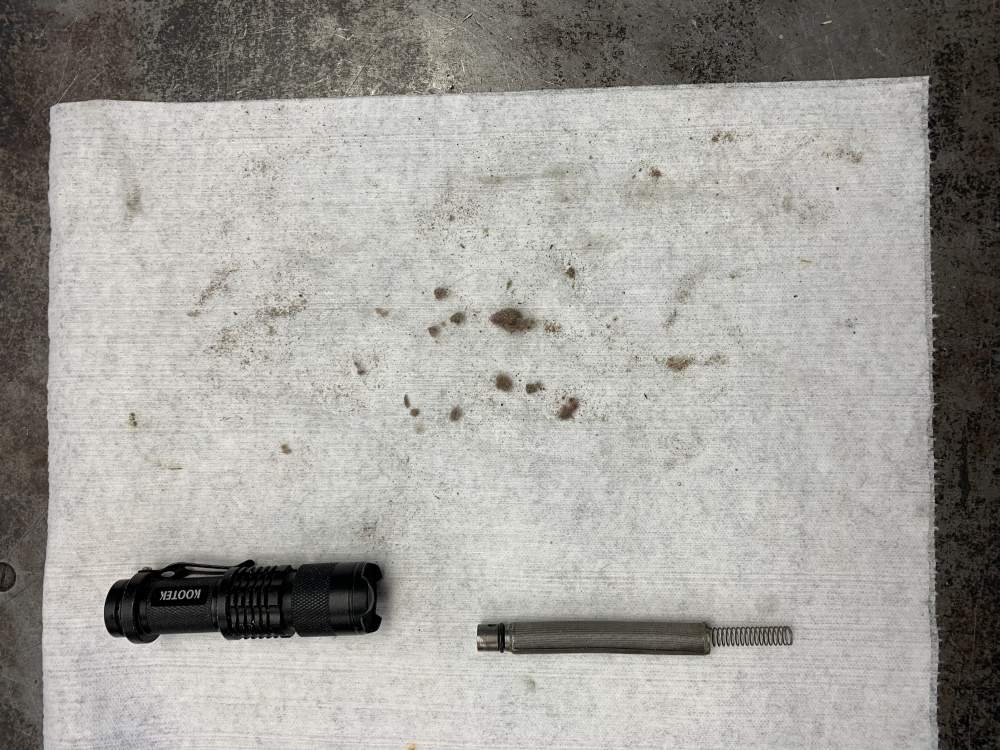
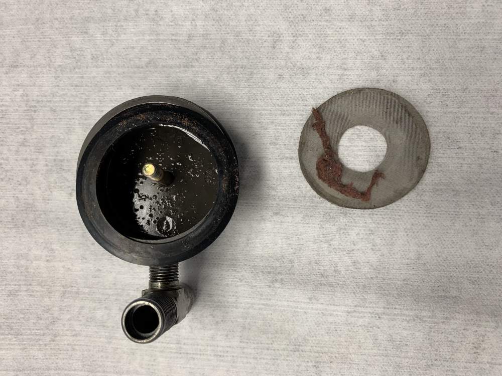
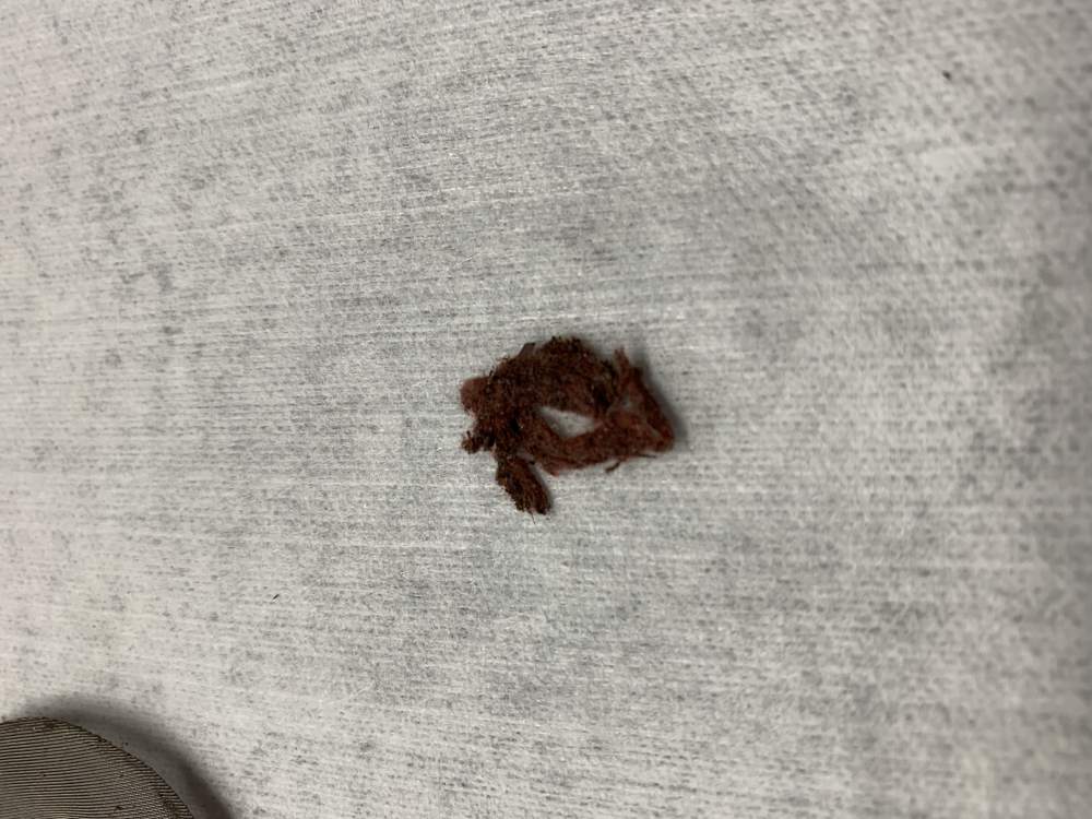
Opened up the gascolator at the annual inspection today and found a significant amount of what I'll call "dryer lint" on the screen. Photos below. Note that the first photo with the material resting on the screen was taken after I'd already run my finger across it, which caused it to roll up into the snake shape shown in the photo. Originally it was evenly caked across the whole screen. The stuff was caked on thick enough to be disconcerting - seemingly enough of it to impede fuel flow, though we haven't seen any fuel pressure or fuel flow issues since the last annual. It's red in color, and looks and feels like cotton fibers. Couple of guys in the shop speculated it's from a fiber washer or gasket, but as far as I know there's nothing like that in the Mooney fuel system. My initial guess was fuzz from a red shop rag, but I don't really think there's a shop rag in the tanks or elsewhere in the fuel system. I'm pretty sure this isn't decaying tank sealant, for two reasons. First, the texture doesn't match what I'd expect of tank sealant. It's not plasticized, rubbery, or gelatinous - again, it's fuzzy like cotton. But more importantly... and here's where it gets weird... all the material was on the engine side of the screen, not the fuel tank side. In other words, it seems like the material is settling into the gascolator from "downstream", opposite the normal direction of fuel flow. I'm not sure how that's possible, but 100% of the material was on the top side of the screen (fuel from the tanks flows through the center of the gascolator to the bottom cup, then up through the screen, thence to the electric fuel pump). Upon discovering the problem, we drained about a half gallon from each tank through the gascolator, and that fuel came out as clear and blue as the pool at a 5-star hotel. Then we cleaned out the gascolator and screen, reassembled, and used the boost pump to run another half gallon through the gascolator and boost pump out of each tank, through the hose that feeds the fuel servo. That too came out nice and clean. So it's a mystery where the stuff came from, and we can't reproduce it. What says the Mooneyspace hive mind? Any and all speculation is welcome.
-
The radios that do the transmitting only have a single mic input (two wires, one for the actual audio and one for the PTT). The behavior of a multi-input system is governed by the audio panel and/or intercom to which the headsets connect. It's possible to set up a system where both mics transmit when any PTT switch is activated. But that would be unusual, because as you said, it's almost always undesirable. I've flown in airplanes with portable intercoms and PTTs which transmit both mics when any PTT switch is pressed, but this is usually an accident of bad hookup/design/PTT understanding. Any panel-mounted setup installed by an avionics shop is going to have independent PTT behavior.


