
47U
-
Posts
1,205 -
Joined
-
Last visited
-
Days Won
5
Content Type
Profiles
Forums
Blogs
Gallery
Downloads
Events
Store
Everything posted by 47U
-
I get the correlation of the poll to the fuel vent thread. I took the poll as an expansion on the subject of ground safety devices as promoting safety awareness rather than a scientific exercise to measure what positive or negative outcomes can be established by their use. My takeaway from the tank vent thread was that a vent (or vent ground cover) could be designed that defeats insects, but allows the vent to function if the cover was not removed. Something along the lines of the little flapper pitot tube cover on my ‘62 Cherokee which used airspeed to function. But then, any additional induced drag by such a device would probably be rejected by the Mooney community.
-
Perhaps, I get it. But I don’t think the object of the poll was to find out how many pilots are out there who have never made a mistake. Kinda like, filing an ASRS to report that nothing went wrong? I’m of the opinion that, if you’re in the game, sooner or later it’s your turn. Just don’t be chronic.
-
Aspen MFD with EI CGR engine monitor
47U replied to Steve Dawson's topic in Engine Monitor Discussion
I’d have to hit the lottery. The Aspen unlock and EI equipment together is more than the list price of the CGR 4 cylinder combo (@ 5.7 amu). And that’s before buying the Aspen MFD… unless you’ve got one sitting around. I suppose there are used MFDs out there removed for upgrades. My UBG-16 will soldier on in its obsolescence for the foreseeable future. -
I, too, am chock afflicted. Twice. As my mental focus is on the sortie into IMC early in my IFR training. With my CFII in the right seat. And once, long ago when I was a crew chief, they told me (when we returned to Offutt) that I failed to pull chocks before climbing onboard my -135. I think they’re lying. I would never do that. ”Over wing and aft hatches checked closed. CHOCKS, ground wires, pitot tube covers, and external ground equipment is removed. Upper and lower rotating beacons on and rotating. Aircraft is in taxi configuration.”
-
You got me, Ross. I’m only vaguely aware that some of the bigger shops have a test stand. I haven’t had the pleasure of experiencing a full overhaul yet, but I did top 3 cylinders in two years a couple annuals ago. Reading the Lycoming (and others) break-in instructions, I took away some important points. Minimizing ground run time, stipulation to have ‘calibrated’ engine gauges, initially run at high power to start, then alternating high and low power settings. Considering that a good portion of the cylinder(s) break-in can occur in the first hour (or so), after a major overhaul, the controlled environment of the test cell seems to me like a good thing. Even from a standpoint of maybe lowering the risk of infant mortality. In my former life, the jet shop ran everything across the test cell before putting in on the jet. Lycon isn’t that far from me… this is on their website: https://lycon.com/testing.php
-
Thank you for the pictures. You have a really nice vintage example. A field overhaul that was not run on a test stand ‘could’ still be breaking in cylinders. If chrome cylinders, perhaps even more so. Your baffling around the starter/alternator shows attention to detail, but the rest of the forward flexible baffling might benefit from replacement. There are some areas showing wear, some questionable areas, especially below the prop where if looks a little funky. If you’re fastidious about making sure the baffle is secure in the channel, it could be fine, but there is some evidence of deterioration both upper and lower. You’re picking up manifold pressure off both #1 and #3 cylinders, both to the firewall? I’m not an expert… the #3 is to an engine monitor? With the PowerFlow, 16.5 to 17.5 might not be sufficient to keep the CHTs where you want them. @Skates97 had a good post on carbs about 5 years ago… I am assuming your PowerFlow exhaust carb heat system is not dumping air like the stock Mooney system. I noted the cold air intake for carb heat was moved from behind #3 cylinder to in front of #2 cylinder, which you mentioned #2 and #4 were your hottest CHTs. Externally, your doghouse looks really good. There’s certainly many in worse shape (including mine). Still, it’s a good idea to do some flashlight testing for gaps. Interesting cowl flaps for a ‘62 C… I’m wondering what event brought those about. An upgrade from normal wear… or an unfortunate event? Please keep us posted on developments… we’re all learning.
-
Welcome, Phillip. Between the PowerFlow and E mag, these CHTs might be what you get. It’s hot in Texas. How many hours on the overhaul? If you’re still breaking in cylinders, there might be some relief yet to come. Was the overhaul done with chrome cylinders? Chrome might run somewhat hotter CHTs. Is the oil temp within expected range? Be sure the flexible baffles around the upper and lower front cowling are in good shape, seated in the groove. Check to make sure the inter-cylinder baffles (below the cylinders) are installed correctly. And check that the baffle tie rods are installed. There are some felt pieces on the back side of the doghouse that close up some gaps. Make sure those are doing their job. The ‘62 has adjustable cowl flaps (I think)… to see if it makes a difference, I wouldn’t be against adjusting them to be open an inch more than spec’d in the mx manual. To see if it makes a difference. Get the speed up as soon as possible after takeoff. 120 is a good target. I understand the urge to gain some altitude on initial climb, but see if emphasis on acceleration makes a difference in lowering CHTs. Enjoy the new ride… let us know how it goes… post some pics!
-
Transponder antenna replacement questions
47U replied to LANCECASPER's topic in Avionics/Panel Discussion
Presumably, the Comant comes with a base gasket? And mounted on a belly panel? I don’t think any RTV is required. I think convention has the slanted side forward, but, being a Mooney…. why not go with the straight end forward. This is the (Mooney) way. -
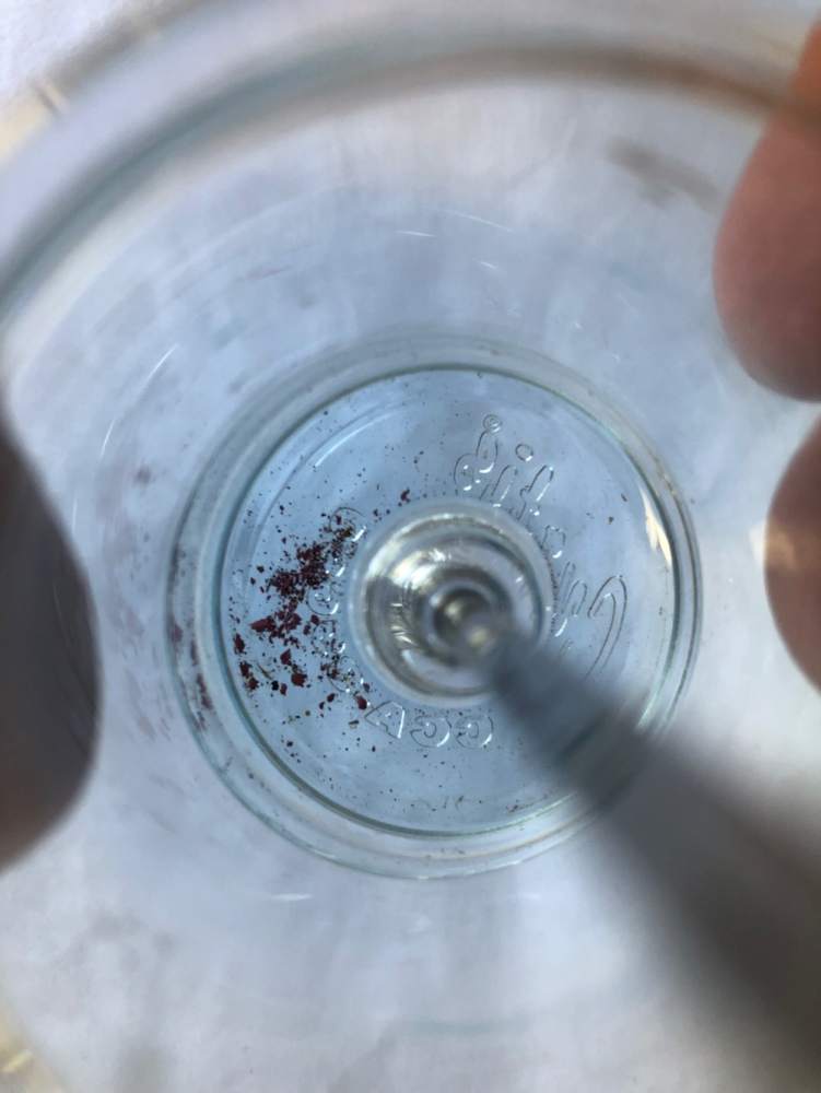
When these little grains started showing up I was concerned. They were soft, so I figured it was the top coat. No tank work in my ownership starting in 2008. No history of a full strip and reseal. Not leaking, just one brown rivet and a couple screws with stains on the wing walk panel. The gascolator and screens were clean, but I got paranoid. I figured this wasn’t going to get better by itself so I got on the schedule in Willmar. Problem solved, no more debris in the sump samples.
-
https://www.controller.com/parts/search?SearchType=Start&PartNumber=c-3532-22p
-
The previous owner of my ‘63 C told me of this… the one time he had carb ice in his 35 years of ownership, he saw the manifold pressure was dropping. I added a carb air temp probe when I installed the FP-5 and have a warning light set at 35 degrees.
-
Aspen MFD with EI CGR engine monitor
47U replied to Steve Dawson's topic in Engine Monitor Discussion
I could be interested… depending on price and availability. I think I could reuse several modules I already have feeding my UBG-16 (which is now obsolete). However, the product was announced some months ago…. -
-
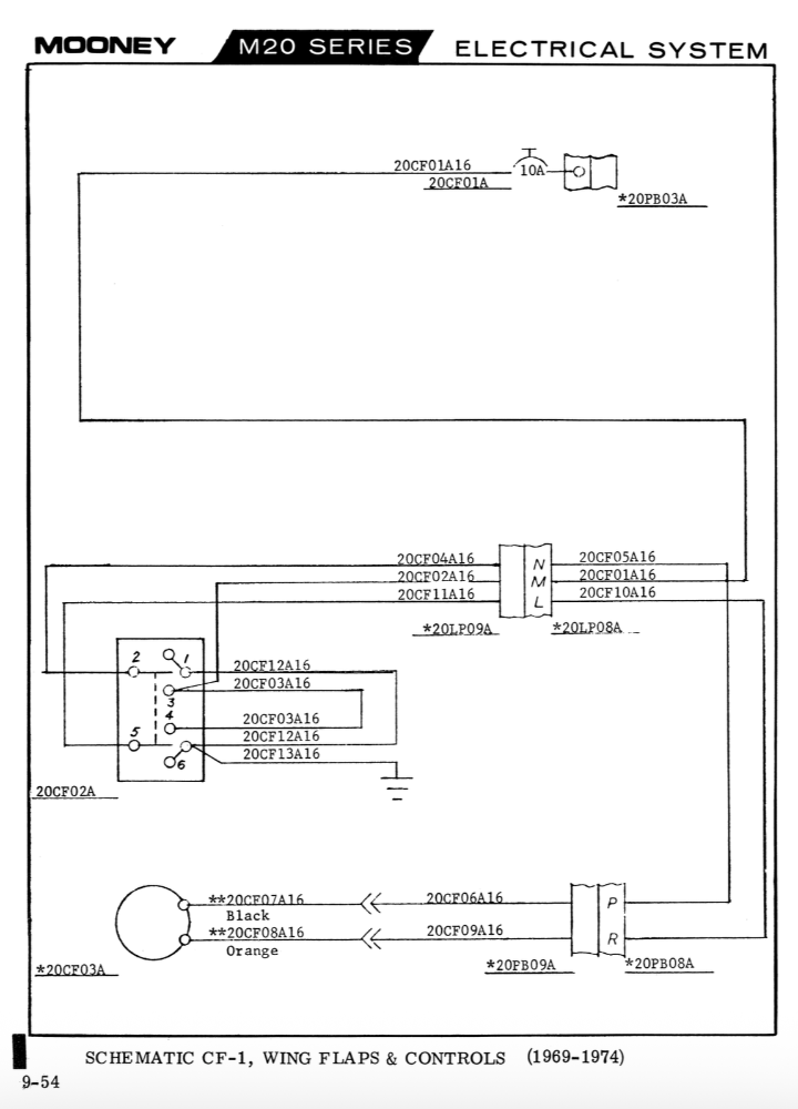
I’d start by measuring voltage at the actuator and compare the up-circuit voltage to the down-circuit voltage…
-
Nope. Not available at any airport that I’ve been to in NorCal…
-
C’mon, Don… you’re not wavering now, are you? Keep the faith!
-
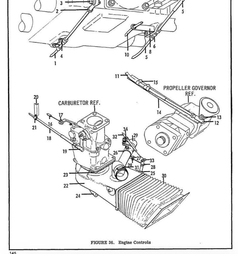
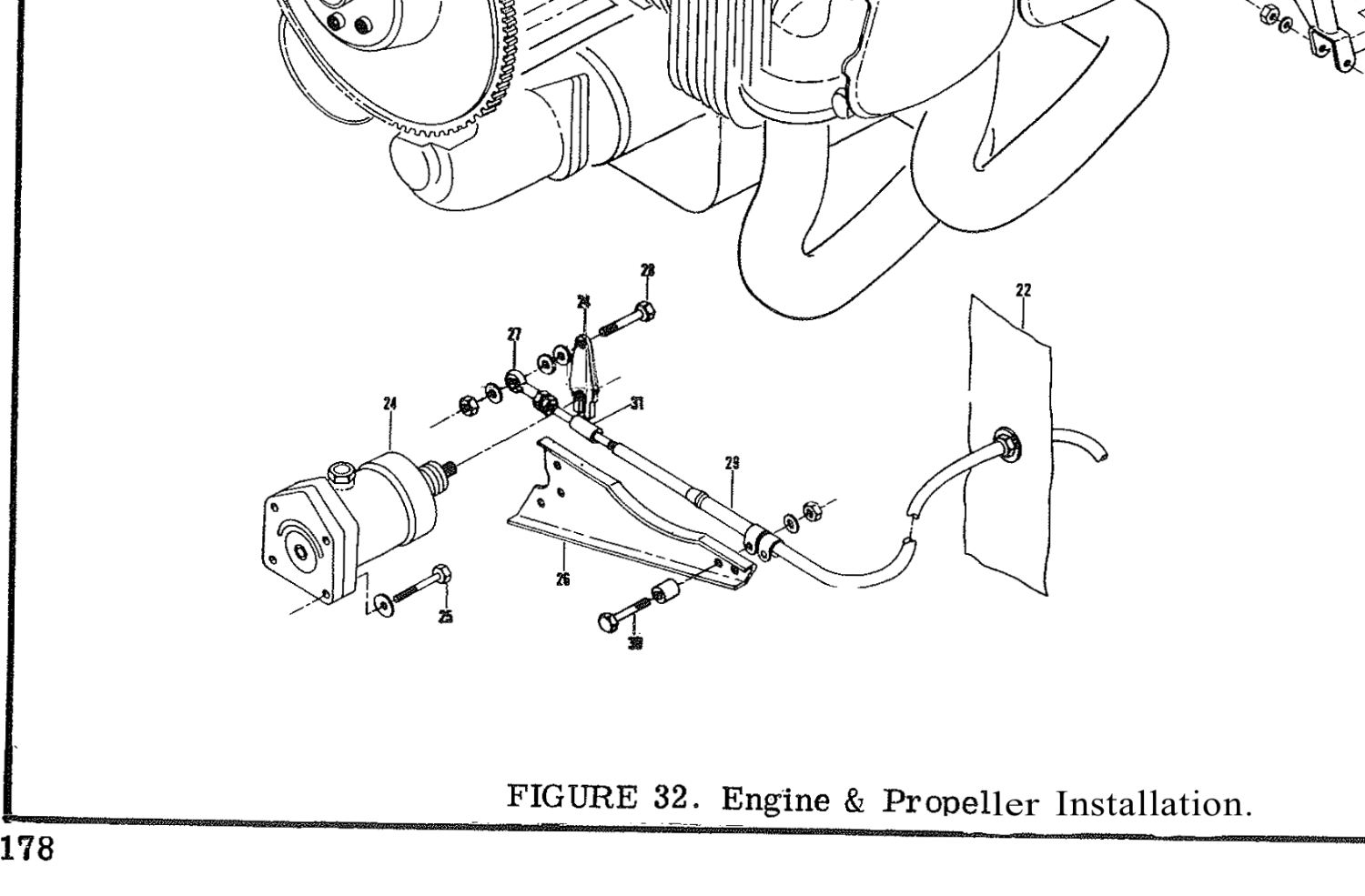
The ‘70 F model IPC shows a cutout in the prop cable support bracket that should eliminate interference with an oil filter mounted on the accessory case. Not accounting for subsequent changes to the configuration, obviously. Looking at the IPC for your year/serial number, I think the ‘67 F model has the prop cable penetrate the firewall on the right side, so the cable support bracket shouldn’t interfere with an oil filter on the accessory case (if that’s what you meant, and not the remote filter…).
-
Installing Spin-On Oil Filter Adapter
47U replied to TheAv8r's topic in Vintage Mooneys (pre-J models)
Here’s the document, but not sure if the dialogue on the Grumman site was relevant. https://www.lycoming.com/sites/default/files/file/2025-01/SSP-885-2.pdf -
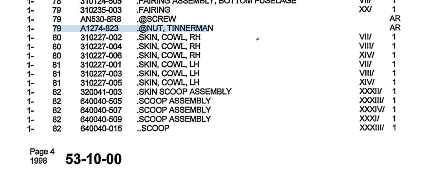
Sheet metal screws go into tinnerman nuts, which are pretty easy to replace. I’m not very ‘J’ smart, but there’s a pn for these in the IPC… Rereading your post… Are you saying the holes in the panels are wallered out to where you need to install a screw with a larger head?
-
Does anyone know where I could get a 3D Printed Switch Guard?
47U replied to LANCECASPER's topic in Avionics/Panel Discussion
Duh. So, Mooney made the switch guards in-house??? Then, they should have a drawing. Front page of the manual says Mooney International Corporation… revised in 2014. Inside pages refer to Mooney Aircraft Corporation, Inc. -
Does anyone know where I could get a 3D Printed Switch Guard?
47U replied to LANCECASPER's topic in Avionics/Panel Discussion
Is the vendor MAC? Whomever that is?
-
Corrosion in Tail. What to do about it?
47U replied to LinvilleMooney's topic in General Mooney Talk
Clean up the rust and primer as mentioned above is the best solution. The access in that area is sooooo restricted. I’ve been hitting it with a wire tooth brush (with a shortened handle) and spraying it liberally with LPS 3 every annual as a stop-gap and that has kept rust under control.
-
A search on controller.com shows a used one for sale at Dawson Aircraft… they’ll probably send you a pic so you can see how worn it is. https://www.controller.com/parts/search?SearchType=Start&PartNumber=560046 One of the salvage yards would likely have a serviceable down lock block.
-
Look for the SWPC STORE link at the top of the webpage. I installed these back in 2011. I got a third light for the A-post. As long as I have one incandescent bulb in the circuit, the dimmer rheostat works just fine. The camera overexposed the panel shot, but the LEDs throw a lot of light. (Hmmm, does anyone need an ARC autopilot, CP136, NAV121&122, KR86, or two Comm 120s?)


-
Has the prop installation index been verified?

