M20F-1968
-
Posts
1,864 -
Joined
-
Last visited
-
Days Won
3
10 Followers


M20F-1968's Achievements
")


-
The downlock block handle is simple to take apart, however you will need to grind down an open end wrench to fit inside the hole on the side of the long handle. Also, use a pirce of duct tape so the nut doesn't fall down inside the handle. John Breda
-
If you have an old downlock block, I have a LASAR version of one that I can sell. It it has no wear at all except for wear of the paint only. The geometric dimensions are original with no wear. I aqcuired =this one with some other parts and already have two spares that are new. John Breda 617-877-0025
-

Mooney M20E 1975 interior piece
M20F-1968 replied to ighazali's topic in Vintage Mooneys (pre-J models)
Parts like this are more easily made than found. Take your could part and use it as a mold. Hand layup a new part. By rights, you should use antimony trioxide into the resin as a flame retardant. Use mold release. Sand and fit appropriately. John Breda -
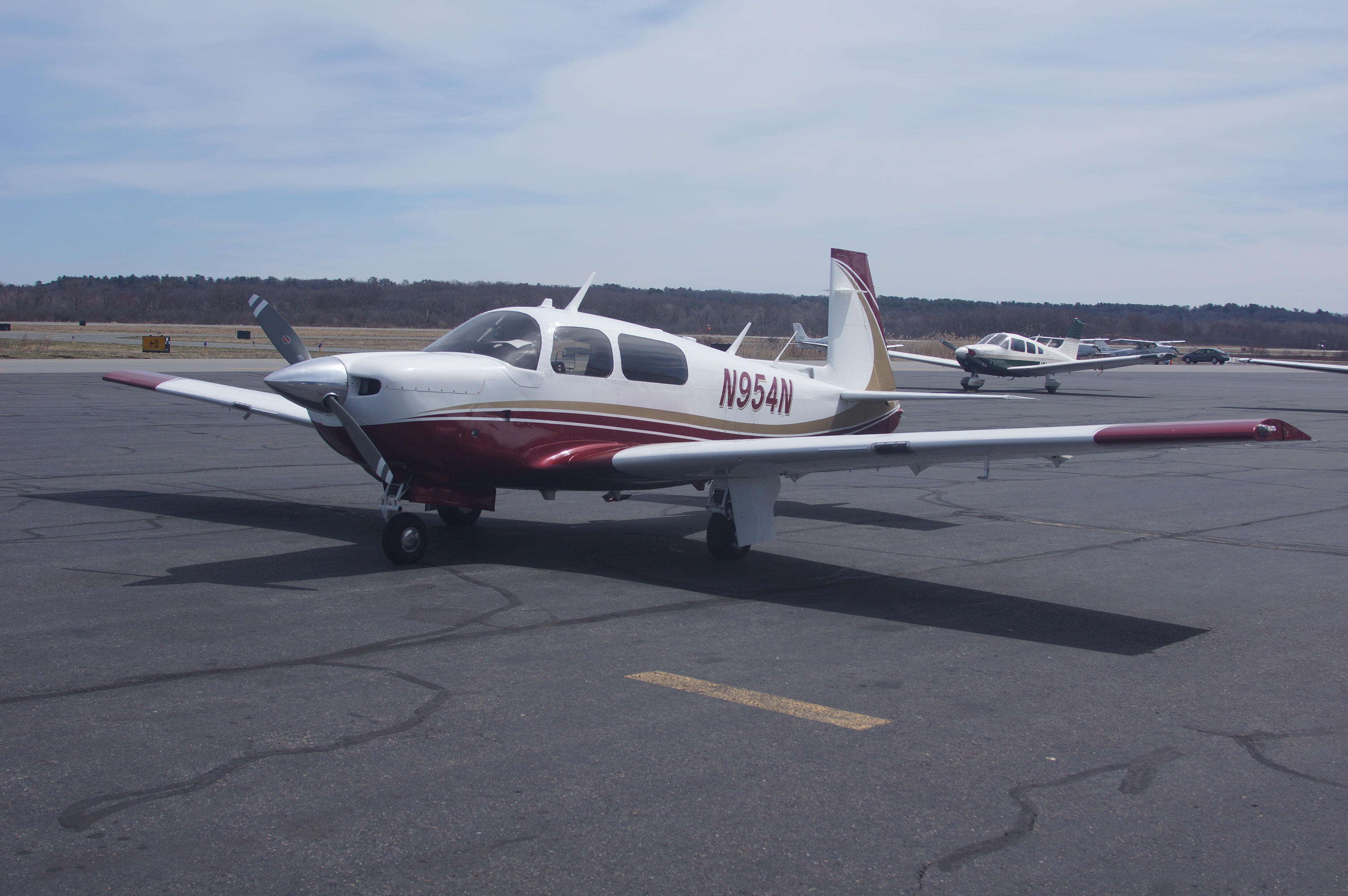
My 1968 F is in the J numbers but took a lot of work to get it there. 10000 ft - 75% power - 160 kts ROP 11.5 GPH 10000 ft - 100% power - 168 kts ROP 17000-18000 ft - 75% power 175-180 kts. 11.5 GPH. (turbonormalized) Take a look at my Album page - You cannot tell it is as F - there is only one - all speed mods except inner gear doors. John Breda
-
I would be interested in receiving a scanned copy when available. My e-mail is: john.breda@gmail.com Thanks, John Breda
-
As Scott mentioned above you may need to change the actual yoke (behind the panel). You will have to change the part that connects the forward portion of the two yoke shafts. The newer style (and I am referencing the Ovation parts which I used) have bronze bearings and are different from what is in the E. John Breda
-
Mooney Lycoming riveted turbo v clamp.
M20F-1968 replied to flyboym20m's topic in Modern Mooney Discussion
It is basic economics, these prices are determined by supply and demand and greed. John Breda -
David, This has been a long time coming but the end result is coming together nicely. Did you place metal strips into the fiberglass to give support to inhibit camlock wear? Nicely done. John Breda
-
I have used Sky-Bolt camlocks since my rebuild. I have the large 4000 series on the rear edge of the cowl, and the 2000 series (but with the large flange which I think are renamed 2800). I have some small nylon washers which I place on the camlock which keeps the camlock from falling out of the cowling low edge (smaller ones are used between the top and lower cowling). It hase been several years and do not know part numbers, but call Sky-Bolt and they will walk you through it. John Breda
-
You can a make glare-shield out of fiberglass fairly easily if you are careful. I will relate what I did to make the upper interior cabin panel in my F, now transformed to mostly a J with Ovation interior. Since it is highly modified I had to modify or make interior parts. One such part is the upper interior panel of the cabin door. My F model door has been reskinned, and fitted with a rounded Ovation-style window, but is not as tall as the Ovation window. Also the compound curvature needed to be changed to fit the door and interior. After many trys of hand layups, I decided to use the pane itself as my mold. I fractured the fiberglass panel so it could be screwed in place on the door. I covered the door and exposed airplane parts with clear vinyl wrap, then screwed the now flexible fiberglass panel in place. Being careful to keep things clean, I hand layed-up layers of fiberglass to make the panel as guided by the panel which was screwed in place. When dried, the panel was worked as needed. You can either use cheap boat yard grade fiberglass, then when the part is finished, use is as a mold to make a fire-proof version, or use fire-proof resin initially. You can place linear supports, use duct tape, or whatever is necessary to support the lay-up part until it dries. Protect avionics, seats, upholstery, etc. with sran wrap or similar. Fabric stores have rolls of plastic wrap of various thicknesses. Use your manual skills and creativity and you can get exactly what you want. John Breda
-
Looking at Buying Unairworthy M20J for $45k
M20F-1968 replied to Ted_G's topic in General Mooney Talk
I just saw the pictures. They suggest the plane has been stored outside which is not good. There is rust around the fuel opening in the wing. Also not good. You do not want to be opening up seams in the airframe. You will be likely spending more that $100,000.00 on this airplane, and likely multiples of $100,000.00. You need to look everywhere for deal breakers, and will need an honest, very experienced person to perform the inspection. It is an airplane that could likely present to you hidden corrosion that will bite you in the ass if not realized up front. You need to know for sure that this is a good candidate to be a major project. This is likely not a $100,000.00 fixer upper, but that answer can only be made after very close examination, John Breda -
Looking at Buying Unairworthy M20J for $45k
M20F-1968 replied to Ted_G's topic in General Mooney Talk
Needless to say, corrosion in the airframe is a show stopper. Was it stored inside or outside. Mine had been stored, in pieces, indoor near Dallas, TX, inside a hangar. There was no corrosion, nor was any found as we ]went completely through the airframe. It depends what you want. I bought mine as a project airpl;ane. My biggest problem was finding honest and competent mechanics as I had endure three dishonest ones before finding the people that helped me make this project a success. It will be a complicated project and you will need to go through each of the systems of the plane in detail. It will be an opportunity to completely update a J to a very nice and capable plane if you want that, but you need to determine, without surprises that it is a good candidate for the investment of money and time. John Breda -
Looking at Buying Unairworthy M20J for $45k
M20F-1968 replied to Ted_G's topic in General Mooney Talk
I completely rebuilt a 1968 F Model to a state of being better than a J, and performs like a J. I was an Oshkosh winner 2X, 2018 - Outstanding Mooney, and 2019 - Lindy Award best of show in class. The connection of the tailcone to the roll cage is the weakest part of the Mooney. If it needs no attention, do not separate it. The airplane cane be moved on a flat bed truck, remove the engine and engine mount, collapse the nose gear, take off the empennage, and put it on the flat bed with the wings aligned along the length of the trailer. A lot can be done to these planes. Find people who have done to work successfully that you plan to do and seek out their advice. I do not know enough about your engine, but get some expert advice. It may be ferryable, or you can do an IRAN or overhaul from where it sits and then fly it out. John Breda -
I think you can get black acrylic. Cut the edges with a scroll saw, sand, and polish with a buffing wheel. John Breda
-
I have an F model not a C, but it is quite tightly packed since it is turbonormalized. I thought I would welcome you to the club of Mooney owners who collect rare but highly useful extra long wrenches, extra short wrenches, extra thin wrench, magnetic sockets, hand ground tools and other desirabless that will be used for those singe applications....... John Breda
