

PT20J
-
Posts
10,078 -
Joined
-
Last visited
-
Days Won
229
Content Type
Profiles
Forums
Blogs
Gallery
Downloads
Events
Store
Everything posted by PT20J
-
Interesting thought. I think it likely depends on whether the filter has an anti-drainback valve or not. Oil flows into the filter can around the outside of the media, then through the media and out the center. If the filter has an anit-drainback valve, air should force the trapped oil through the media and out the center, so it is being filtered. The anti-drainback valve in the filter should prevent unfiltered oil from blowing down through the oil pump. But if there is no anti-drainback valve, the air would probably force oil back through the pump because that path would be lower resistance than through the media. Either way it seems like the trapped oil on either side of the media shouldn't be much different in terms of contamination unless the engine is making a lot of metal. https://aeroaccessories.com/wp-content/uploads/2019/01/Tempest-OilFilterValves-Final.pdf
-
Only if you use a very long tow bar.
-
When I was talking over my nose gear claim with my insurance adjuster he related to me that they hate writing FBO insurance because they all have young low paid guys driving tugs and fuel trucks around expensive airplanes. He was currently working a claim by an FBO for a kid that ran a fuel truck with a mid-stowed ladder sticking out the side into an engine cowling and along the fuselage of a BBJ (corporate 737). The damage was 7 figures requiring Boeing engineers to fix it. I once worked at a flight school where the new line boy tried to taxi an Archer to the wash rack and hit another airplane, panicked and steered into the tail of a Navajo where the prop made 3 slices through the tail before stopping. FBOs are dangerous places for airplanes.
-

Owner assisted installs/Budget ideas?
PT20J replied to BlueSky247's topic in Avionics/Panel Discussion
I got mine (It was a first class radiotelephone license back then) during my senior year in high school. Used it to get my first summer job babysitting a 50kW AM station transmitter. Never had to do anything except write down all the meter readings every half hour and sign the log. I spent most of my time making music tapes from the record library. It was indoors and paid pretty well. -
On mine the controls to recline the rear seat backs are in the center and this is why I think Mooney put it on the left side.
-
Sorry, missed that. If it's not the cover, and it's not the gasket then it must be the cylinder.
-
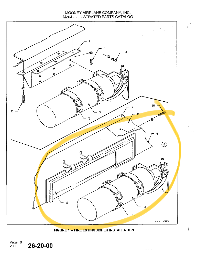
Behind you. It would be beneath the legs of the passenger seated in the left rear seat. The trim panel beneath the seat cushions is straight, but the spar is swept forward on each side from the center splice creating a space between the trim and the spar and this allows for a recess that the extinguisher mostly fits in to.
-
I am not in any way saying this is the OP's fault, but I think the lesson here is that if someone moves the plane the preflight should include careful examination of the nose gear leg and truss. And, no, I haven't always done that. When mine was tug-damaged (not by Signature), I happened to think it was parked in a space between hangars that would have required a lot of maneuvering and that's why I happened to check it and found one of the stops broken off. I was lucky because the tube was dented less than the 1/32" allowable and I was able to fly it home. The nose wheel only steers 11 deg left and 13 deg right. Assuming a ten foot towbar, the tug will be offset from centerline only about 2 feet left and 2.3 feet right. I don't think the guy that broke mine even knew he did it. Before Mooney started welding the stops to the nose gear leg, the only stops were on the rudder push pull tube in the tail. The newer stops on the nose gear leg help, but are not really all that strong.
-
Different engine, but...I had a rocker cover leak on my Lycoming IO-360 and it turned out to have a pin hole in the metal.
-
I would give serious thought to mounting it somewhere else, if I could find a place. Normally I'd mount it to the pilot's seat, but that doesn't work with the articulated seats. It's really useless mounted in that recess on the front of the spar where it is darn near impossible to access.
-
I’ve had good luck getting info from Frank Crawford. He doesn’t send complete drawings, but emails me enough of the drawing to make my IA comfortable.
-
Signature opened an FBO at San Jose CA well after Atlantic took over the San Jose Jet Center, so there is at least one airport where it’s not the only FBO.
-
Yep. And, it’s a terrible location. Insccessible from the pilot’s seat. I have to get down on the floor behind the copilot’s seat to wrestle it out.
-
@DonMuncy was kind enough to send me his pattern which I used to cut down the Rosen’s.
-
On my 1994 J, it’s just a standard fire extinguisher bracket pop riveted to the spar through the plastic trim piece.
-
Probably it depends on the FBO. If I were a large FBO, my fear would be that someone with a damaged gear would fly to my location and then claim I caused the damage figuring I had deep pockets. With a date/time stamped photo, I can show that it was good when I arrived. Now, if they are just jerks and say, “so sue me”, then it wouldn’t help.
-
I'm curious what the repair cost? When Atlantic screwed up mine and refused to pay or share the surveillance videos, I just let my insurance handle it. So, I was out nothing but a little time arranging parts and repairs. It was a small claim and not my fault so it didn't affect my rates. Ultimately USAIG was able to get reimbursed by the FBO. Problem for me was that I couldn't prove it. Now, I take pictures.
-
Each elevator is connected to the bellcrank in the tail by a push-pull tube the length of which is adjustable by screwing in or out a rod end (service manual figure 27-5). The elevators are suppose to have equal deflection up or down (22 +/- 2 deg.) So, you could measure the travel on both sides and which ever is closest to equal travel in each direction would be correct (assuming that only one is misadjusted) and you could adjust the other to match it.
-
Normally we keep calculated W&B history because errors are common and keeping all the calculations provides a way to go back and find errors. If the airplane was reweighed and all subsequent calculations are based on that, there is no reason to keep the old W&B calculations prior to the reweighing. Any AFMS for removed equipment are no longer pertinent and should be removed. I keep a separate file of documents that no longer apply just in case I want to look up something historical.
-
Is that a crack in the baffle (bottom right of the baffle, lower left of the picture)?
-
Oil analysis and filter examination detect different issues, and that's why we do both. Chips in the filter are often too large to show up in oil analysis and suspended metals in the oil are too small to be trapped in the filter media. That metal in the filter is not excessive and may or may not be related. The significant increase in aluminum in the oil analysis means something. Aluminum usually comes from pistons or piston pin plugs, but in this case it might be do to some fretting of the cylinder against the crankcase. While the cylinder is off will be a good time to check the camshaft. I would carefully preserve any evidence if I suspected that this failure was due to an installation error.
-
Bolts are springs. They work by preloading them so that they stretch within the elastic limit of the material and the spring force thus created is what holds the parts together. The design requirement is that the preload must exceed the force on the stud under load. In this way, the stud doesn't feel the load and the joint stays tight. It is important that the materials being joined have less elasticity than the bolt. This is why paint under the nut or sealant between the joint is problematic. It is also why lock washers are not used under cylinder nuts. The first thread from the shank is the most heavily loaded, and that's usually where the stud fails. There are two primary failure modes: 1. The nut was installed with insufficient preload (torque), or lost it's preload, which allows the stud to feel the load and eventually fail due to fatigue. This causes a pretty clean break. 2. The nut was overtightened which causes the stud to stretch beyond its elastic limit and neck down leading to a tension stress failure. From the pictures, it looks like 1 to me. If the cylinder had actually become loose enough to move a mm or two, the studs would have all stretched under the load and failed under tension and the cylinder would likely have departed the crankcase.
-
It’s really a Micky Mouse arrangement. It takes some fiddling and trial and error and it can also create a hard spot in the movement of the throttle cable where the switch actuator rubs on the ferrel that attaches the cable to the throttle shaft. And you have to wedge yourself into the pilot’s footwell to get to it. Where to set it is up to you. The POH says it comes on when the throttle is about a quarter inch open. The service manual says less than 10” MAP. I set mine for 12” MAP. Mark the throttle shaft with a sharpie in flight when it is set for the manifold pressure where you want the warning to occur. Then on the ground set the throttle to the mark and adjust the switch to just activate.
-
No, I had a GTX 345 and a GNS 430W and they worked together fine. You need an unswitched audio input available on the audio panel for the GTX.
-
Hard to tell without actually being there. The nose wheel only turns around 12 degrees so it doesn’t take much offset (especially if it isn’t rigged correctly) to put bias on the interconnect (to answer @hangareuro’s question, there are no other springs in the aileron controls). You can do a quick and dirty check by using the towbar to position the nose wheel so that the rudder is one deg right. That should result in the ailerons being centered and the nose wheel being approximately centered (there is a lot of slop in the steering system so the only way to really tell is to jack it up and c-clamp a bar across the rudder pedals and see if everything lines up, but doing it on the ground with the towbar should point out any gross issues).

