

Jake@BevanAviation
-
Posts
229 -
Joined
-
Last visited
Content Type
Profiles
Forums
Blogs
Gallery
Downloads
Events
Store
Everything posted by Jake@BevanAviation
-

KX-155 LED display warranty or fix
Jake@BevanAviation replied to FlyingDude's topic in Vintage Mooneys (pre-J models)
We have seen some LED mods fail but it's pretty rare. For out of box failures BK has replaced the failed display but the process does take some time. If I had to guess for a manufacture warranty, possibly around 90 days. The display connector is prone to failure so that is a possibility or we have seen some of the contacts on the LED board cause issues. As for the website you linked, it's not a approved mod and we have never seen one in person but have had multiple inquires about it in the past. The only approved mod for the old gas display replacement is the LED mod. -
Best repair shop for ky-96.
Jake@BevanAviation replied to rotorman's topic in Avionics/Panel Discussion
My guess would be a display problem or possibly a display conductor strip problem. We do have new displays and the conductor strips available but if you want to send the units in we might need to order more conductor strips as we only have 3 in-stock and there are 2 per unit. You can give us a call at 316-946-4870 and ask for Thom or Mike. They are the techs that work on these units and would be able to answer any additional questions you might have. I did briefly talk to them about the issue and they said the display strips are a common problem and if you gently push on the display and the digits come back that might be the issue. Just be careful to not push to hard and break the display. -
The manual list the lamps as 037-0032-09, there is a special lamp for the DH illumination of 037-0049-01. I do not work on any indicators and I would suggest to only have the indicator repaired at a appropriate rated instrument repair shop.
-
KfC-150 test fail question
Jake@BevanAviation replied to Will.iam's topic in Modern Mooney Discussion
If you want to stay in the Dallas area you might reach out to Trevor at Tech Aero in Denton. He is an amazing tech and knows how to efficiently troubleshoot these legacy systems. You want to bring the aircraft up, just give us a call to make sure we have the room. If Trevor wants to remove the servo and cold soak it then check the voltage regulation that is where I would start. -
KfC-150 test fail question
Jake@BevanAviation replied to Will.iam's topic in Modern Mooney Discussion
The trim servo has a voltage regulator that generates a regulated voltage off the trim power. This voltage is used for MET (manual electric trim) and is monitored by the flight computer in the event the regulator fails to annunciate a trim failure condition. It is possible that in the colder temps the voltage is just out of mfg. specs for the monitor circuit in the computer. As the components warm up, the voltage falls within specs and the failure warning on pft goes away. If the regulator fails and goes INOP you have no MET functions and a constant warning from the flight computer. I would be curious to see where the regulated voltage was when the unit was cold. There is a zener diode in the trim servo that could be replaced to increase the regulation in cold temps if it is too low. During PFT, the computer sends two up drive pulses and two down drive pulses to the trim servo and monitors the feedback lines to see if the motor is functioning. If you are getting the 4 trim light flashes during PFT we can assume the computer is sending the commands to the servo and looking for feedback. If for some reason the motor does not run the system will fail the PFT. During this test the solenoid will not pull so you won't see the trim move in the aircraft. -
@jaylw314 It can be repaired, typically we send the sticking needle issues to Mid-Continent instruments for repair.
-
It's not uncommon to have the G/S pointer stick on the KI-525. If the pointer gets stuck you can take the palm of your hand and bump the panel around the instrument. After bumping the panel they will drop into view and respond correctly until it gets stuck again. Only way to really fix this is have a instrument shop open the indicator up and clean/repair the G/S pointer assembly.
-
@goodyFAB The main problem with the Century 41 system is that Century is no longer supplying parts for the majority of the assemblies. This applies to all legacy systems they produced. Without the correct parts repairs will be extremely limited. The last discussion I had with the owner of Century Flight System they stated that they were no longer doing repairs at the factory. The Century 41 flight computer is full of ribbon cables that delaminate over time and cause major issues when trying to repair the unit. The last Century 41 I sent to Century for repair which had alot of ribbon cable issues and other board assembly issues came back with a 9k estimate for repair. This was a couple of years ago before they shut down factory repairs. I do have the test set and the manual for the Century 41 system but depending on the failure, parts might not be available. I would not be surprised to find delaminated ribbon cables inside the unit and I do not have any replacement cables for the Century 41. You can contact Autopilot Central and see what they say but they will have the same issue I have with parts unless they have a supply of new parts available. Century Flight Systems are in a pretty bad spot, with personnel retiring and no new trained techs for legacy systems available, no new products to market, it looks pretty dim for the future. What I tell any customer that has a Century 21, 31, 41 or 2000 is if the system is still working keep it going, but start saving for a future upgrade as part availability will severely limit the systems ability to be repaired and supported.
-
@pkofman I have not personally seen an instance where a failed KAS-297B would cause the KC19X flight computer to not pass PFT. The alt pre-selector was an optional system that could be added to the KFC150 system. It does get information from the flight computer system for oscillator and digital data. There is the possibility that if the unit were pulling the oscillator low that it could cause the flight computer to fail a PFT. If you wanted to isolate the KAS-297B out, I would just unplug the unit and then try the PFT on the flight computer. I would not be surprised if the flight computer you have has capacitor leakage in the power supply circuit. This is a known issue with units manufacture from 1993-1998. Are you getting the 12-13 flashes of AP on a successful completion of the PFT? Also, when the unit fails the PFT do you get the flashing trim fail annunciation or is the unit completely dark?
-
The KC19X is the model number of the flight computer. KC190 is a KAP100 flight computer. KC191 is a KAP150 flight computer. KC192 is a KFC150 flight computer. The individual part numbers of the flight computer will differ from model to model and are voltage specific.
-
King part numbers are 037-00032-0010 for 28v lamps 037-00032-0008 for 14v lamps
-
We do not work on the KAS-297B. I would suggest Mid-Continent Instruments, Duncan Aviation, or Southeast Aerospace for evaluation/repair. To my knowledge the only box that works in place of the KAS-297B is a GAD43e that is paired with the G500/600 glass displays.
-
To replace the lamps in the KC19X unit, the bezel has to be removed. To do this, the unit has to be opened up. Some of the screws are only accessed from the inside of the unit. Whoever replaces the lamps in the flight computer make sure they are spaced properly, if they are too close to the lens it can burn it over time. We do not work on the alt pre-selector (KAS-297B).
-
KAP 150 not cooperating
Jake@BevanAviation replied to WaynePierce's topic in Modern Mooney Discussion
@WaynePierce 12-13 flashes of the AP light should indicate a pass. If the compass valid is inop on the GI275 it will not allow you to select any lateral guidance mode. Basic roll only mode should still work for wings level. On the side of the unit should be a red 4 digit stamp. Typically it is on the back of the unit around the transducer static port. For example 4685 would be the 46 week of 1985. Units made from 1993-1998 have capacitor leakage problems. This can cause issues with the unit passing PFT or allowing it to engage. There is also a current sense resistor in the computer that has very tight tolerance, if it falls out of tolerance it can cause issues with intermittent disconnects. Any time I get a KC19X unit in for repair I always replace the current sense resistor as preventive maintenance. Thom Duncan Avionics in Fayetteville is pretty sharp on the KAP/KFC150 system. If you need a shop to troubleshoot the aircraft that would be my suggestion. Another option would be a loaner unit, I might have something available but I would need to know what your dash number is. If you have any questions or concerns just give me a call. -
KAP 150 not cooperating
Jake@BevanAviation replied to WaynePierce's topic in Modern Mooney Discussion
@WaynePierce if you are able to get a video of the PFT sequence that would be very helpful. -
KAP 150 not cooperating
Jake@BevanAviation replied to WaynePierce's topic in Modern Mooney Discussion
For the KAP 140 when changing from a DG to HSI they have to be reprogrammed via a laptop. The KAP/KFC150 has sealed resistor modules that can not be re-strapped. They are specific for the air-frame installation and the flight computer options (FD or no FD, DG or HSI). If you went from a DG to a HSI the top resistor module would have to be changed. Any time you change the attitude source you have realign the flight computer to the new attitude source. This is even mentioned in the installation manual for the GI275. When you were doing the PFT test in flight did you get the proper sequencing of lights (4 flashes of trim, 12-13 flashes of AP)? If you did not get the sequence listed below there is something missing that the computer wants during PFT. Things that could cause a disconnect in flight are listed below. Faulty disconnect switch Faulty return springs in the MET switch assembly not returning the switches to center. Faulty gyro valid relay in the GI275 Activation of MET (manual electric trim) switch with the AP on Failure of the power supply monitor circuit in the KC191 Loss of compass valid from the GI275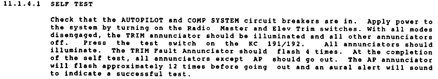
-
@0TreeLemur I am pretty sure we have new knobs available. Give us a call Monday and ask for Mike, he should be able to give you a rough idea of what the repair cost would be.
-
Death of a vacuum attitude indicator
Jake@BevanAviation replied to RobertGary1's topic in General Mooney Talk
Slow erection or excessive noise from the indicator are always signs that the bearings are worn and eventually the rotor speed will be to slow to maintain rigidity. Try to make note of the gyro orientation as the gyro is spooling up, a fresh overhaul always has a nice shake out of the indicator as the rotor speed is increasing. When the bearings get old and stiff you will see a reduced shake out or none. If you witness the AI no longer shaking out during the initial start of the aircraft, that is a sign that the indicator is getting worn. Always replace the filter when replacing the AI. -
@VA FLYER I would assume someone would have to get approval from Castleberry if it was still under warranty to try and repair the issue. The instance I had was the AI would intermittently loose the roll output signal. I removed the AI from the aircraft and put it on the bench, gave it some excitation for the outputs to work, put it in a constant bank around 10 deg and monitored the output. Without influencing the AI I could see the signal drop out and come back after some time. This was in a Duke with a Century 4 and a replacement electric Castleberry AI for the Century 4 system. A shop in Florida had spent months trying to figure out the issue but with it being intermittent some flights were great, other not so much. The main issue was randomly it would start a oscillation chasing the heading bug but the longer the oscillation went the more drastic the banks would get. As the oscillation continued the aircraft would be doing large s-turns chasing the heading bug at a very aggressive bank. When the AI signal came back it would stop and track the heading like normal. If this sounds close to what you are experiencing I would suggest to have the AI put on a bench and have it double checked for intermittent outputs. This can also be done in the aircraft but it won't be easy. If you need a shop to help troubleshoot this issue I would suggest talking to Jason at Freedom Aviation in Lynchburg VA. I have been working with Jason for years helping them troubleshoot autopilot issues. If you want to chat about the issue just give me a call.
-
@VA FLYER I have seen a couple of Castleberry electric replacement AI's have issues with solder joints that have caused this same behavior. If it was me I would be checking the AI on the bench and looking at the output. The FD bars are a representation of what the flight computer is commanding.
-
If the aircraft is banking more than the standard rate turns (approximately 20-22deg bank), that sounds more like a AI issue. When this happens if you tell it to turn right 90 deg it will continue to turn right until you tell it to stop, they are overly aggressive in commands due to the missing information from the AI to limit the response of the autopilot. If you don't tell the system to stop turning, they will turn over on itself.
-
GFC 500 Autopilot Install Costs
Jake@BevanAviation replied to MisfitSELF's topic in General Mooney Talk
Most of our quotes were in the 22-28k range depending on options. -
@Sue Bon The very early Century IIb units that specifically had the square white push button switches had griplet boards. The griplets connected traces from the top of the board to the bottom of the board and have a history of being intermittent and a pain to troubleshoot. Also, the white push button switch had contacts that were prone to spreading over time that would cause intermittent signals. When the system looses the heading error voltage, it will default to the roll centering pot. If the roll centering pot happens to be set for left roll, that would be the direction the system would drive if it lost the heading error. When you turn heading mode off, it defaults to the roll turn knob and the roll centering pot for correction commands. Later revisions of the Century IIb changed to through-hole circuit traces and did away with the griplets. They also change the push button switch to a white rocker switch that controlled a micro switch to provide the heading error to the system. A very common issue with any legacy Century system is the blue amphenol female split pin connector, it has a history of being intermittent. They used this connector on a variety of different components.
-
@N201MKTurbo The Century 21 has no roll knob function. This was a feature in older Century systems. Depending on where the bank angle is set for the individual system, 30 deg bank is very close to the limit of the system. Heading errors typically default to the around 20 deg limit for most legacy systems (book spec for the Century 21 is around 24 deg). This can vary based on where the limit pots are set for the aircraft. For the example given of 30 deg right bank, that is beyond the 24 deg heading limit (book spec). In theory, when it is beyond the max bank limit no amount of right heading bug error would allow the unit to continue to drive to the right. A good rule of thumb is when possible always try to null the AI when doing ground testing or simply unplug the AI for ground test. When you unplug the AI the computer thinks it is getting nulled information back from the AI. If the circuity is working properly you should be able to fully control the system on the ground. Just don't forget to plug the AI back into the system or you will have a very interesting ride.
-
My guess is part of the drive circuitry for the roll servo is faulty resulting in only drive in one direction. Possibly a set of faulty drive transistors. First try reseating the unit in the rack and see if that resolves the issue. If the issue is intermittent it could be a issue with the flight computer, roll servo or possible wiring. Additional troubleshooting would be needed to isolate the problem. If you are doing ground testing make sure the AI is spooled up and as close to level as possible. If the AI is laid over the system will try and drive the servo to correct the laid over orientation of the AI. For example, if the AI is laid over 30 deg to the right indicating a right bank, the system will want to drive to the left to return to wings level with the heading bug under the lubber and heading mode selected. Heading drive will be limited in this scenario, you would be able to drive left but very limited drive to the right if any.

