

Jake@BevanAviation
-
Posts
213 -
Joined
-
Last visited
Everything posted by Jake@BevanAviation
-

KFC 150 self test, trim failure
Jake@BevanAviation replied to slowflyin's topic in General Mooney Talk
You can back pin the connector if you take the back shell off or use a test box which we have. -
KFC 150 self test, trim failure
Jake@BevanAviation replied to slowflyin's topic in General Mooney Talk
28VDC input power, 25-27VDC regulation on pin A. If you monitor pin A with the servo connector plugged into the ship you should have 25-27VDC. Anything outside that spec would cause a PFT failure and if the voltage was too low MET would not be functional. -
KFC 150 self test, trim failure
Jake@BevanAviation replied to slowflyin's topic in General Mooney Talk
What is the long part number of the trim servo and I can tell you what the regulated voltage should be. -
KFC 150 self test, trim failure
Jake@BevanAviation replied to slowflyin's topic in General Mooney Talk
During the A/P test, the 4 flashes of trim is two up pulses and two down pulses to the trim servo. The computer sends this drive and looks for feedback to see if the motor ran or not. You never see the motor turn the capstan cause the solenoid does not engage during this test. However, if you listen for the trim servo to run in the tail you should hear it run 4 times then stop. If MET (manual electric trim) is not working I would check the regulated trim voltage (pin A of trim servo connector). This has to be within a certain tolerance as the autopilot (KC19X) monitors this voltage. If this regulated trim voltage is not within a certain tolerance or missing the unit will fail PFT. -
HSI not aligned with mag compass
Jake@BevanAviation replied to redbaron1982's topic in General Mooney Talk
I would start by double checking the compass system to the wet compass on a compass rose. That should give you an idea as to which system is off. If the issue is the KCS-55A compass system, possible components that could be a problem would be the KG-102, KMT-112, KI-525, slaving accessory. There are adjustment pots on the slaving accessory to help align the system. The adjustments for the slaving accessory are for N/S and E/W. If the system was consistently off around the compass card I would say adjust the KMT-112. If only 2 points (N/S or E/W) were off try adjust the slaving accessory. If you need help troubleshooting the system give Ronnie Tucker a call (Onsite Avionics) 713-254-9367. He is based out of Willis TX and has a mobile service. If the KG-102 needs to be evaluated contact Jerry at Porter-Strait in Tulsa OK. Unfortunately, we do not have the capabilities to repair the KCS-55A compass system. -
New GI275 install; problem with KAP150 integration
Jake@BevanAviation replied to Alangj's topic in Avionics/Panel Discussion
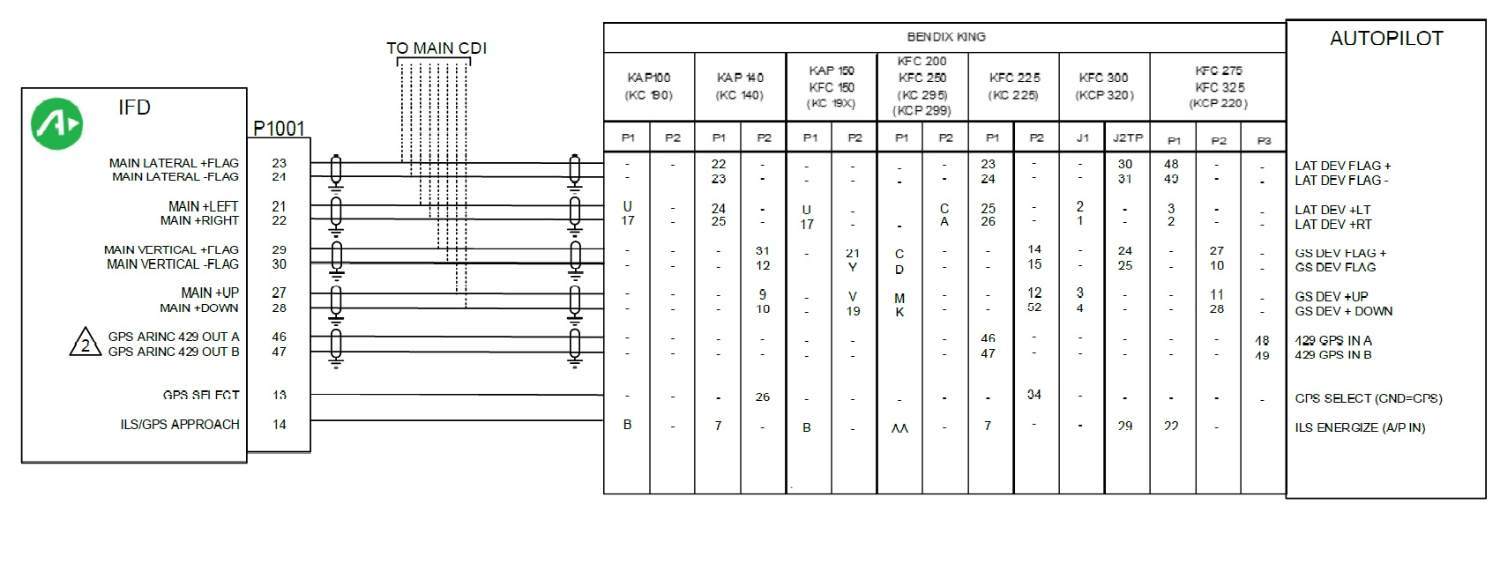
Anytime the system is over banking there is a issue with the AI information or the alignment of the system. For example, if you rotate the heading bug 45deg right of the lubber line the aircraft should go into a 20-22 deg right bank and hold the bank until the HDG bug is approaching the lubber line. Without the AI information the system will continue to turn to the right until you tell it to stop. This is situation can lead to a dangerous attitude if you are not watching the bank attitude of the aircraft. All the interconnect drawings for the system and the alignment procedure are listed in the Garmin IM. If the shop is knowledgeable about how the GI275 is interconnected to the legacy system they will know how to test the attitude response on the ground. The GI275 ADAHRS +AP unit is perfectly capable of driving the legacy autopilot system. The key is knowing what information the system wants and how to get it to the system. -
I would double check the wiring to the KFC225, specifically the gps select and ILS/GPS approach.
-
Autopilot doesn’t decend
Jake@BevanAviation replied to warren.huisman's topic in Avionics/Panel Discussion
Unfortunately, I have never worked on the Trident system and I don't have any service manuals or test sets for that system. -
Ovation KFC150 Roll Servo Replacement
Jake@BevanAviation replied to Greg_D's topic in Modern Mooney Discussion
@Greg_D I can work on the servo but some of the parts are very limited and Honeywell is making it difficult to order replacement parts. If you need someone to remove the servo you might reach out to On-Site Avionics or General Avionics. If you are going to call General Avionics do it early in the morning and ask for James. For On-Site Avionics the contact is Ronnie. -
Ovation KFC150 Roll Servo Replacement
Jake@BevanAviation replied to Greg_D's topic in Modern Mooney Discussion
KS-178 roll servos are unlike the KS-271 servos were you just remove the servo from the mount. The whole servo assembly must be removed from the aircraft on the KS-1xx series of servos. The removal isn't overly difficulty just time consuming. -
@brianucsf With the Aspen PFD and the EA100 if the PFD gets a red X on the display, the EA100 will cause the flight computer to disengage. The EA100 is interconnected with the flight computer in a manner that it will not allow you to engage the system with a invalid attitude signal. Typically, you will get a amber fail annunciation from the annunciator tied to the EA100 somewhere in the panel. Normally they are within pilots view of the PFD. Refer to the Aspen IM for details. The Aspen ACU provides the flight computer with input errors like heading, course, left/right deviation, up/down deviation, GPSS, ect. If something fails in the ACU the flight computer will follow the failure. For example, if the heading output from the ACU was to fail and get stuck at a constant voltage the computer will not respond to heading bug changes correctly. ACU failures can happen just not frequent. All King servos can have motor, tach generator or drive transistors issues at some point. Typically when the drive transistors fail you will only get drive in one direction, or constant drive one direction. One thing I always ask is how are the FD bars responding to input changes. If the FD bars respond correctly to input error changes that checks about 95% of the drive circuitry inside the flight computer. There is one op amp stage left in the flight computer the generates the servo command voltage. This op amp can fail but a simple voltage check at the servo connector will tell us if the computer is the problem or the servo. The control head a/p engage lever is know to have issues and is a pretty common failure. Inside the unit the lever switch holds a small piece of metal. When you engage the system there is a coil inside that will become a electromagnet when voltage is passed. If the plastic tabs break on the lever that holds the metal piece there is nothing for the electromagnet to grab and the switch will not latch. The coil can fail but it is much more common for the plastic tabs to break. There are several other things that can cause issues and after reading your post it sounds like you have a couple of issues. If you would like to give me a call Monday I can tell you what I would look for.
-
KFC 150 Autopilot misbehaving
Jake@BevanAviation replied to IvanP's topic in Modern Mooney Discussion
Possible compass valid issue? If you lost the compass valid input it will disconnect the system when you have a lateral control mode selected. However, if the valid was still missing it should not allow you to select a lateral control mode and engage the system. Vertical modes will work without compass valid. What compass system do you have in your aircraft? It is odd that you were able to re-engage the system in FD and ALT hold and not have any issues for a extended period of time. -
KFC 150 Autopilot misbehaving
Jake@BevanAviation replied to IvanP's topic in Modern Mooney Discussion
@IvanP There are multiple things that could cause the system to disconnect in flight. The key is being able to identify which one. Listed below are some examples of failures that will cause a disconnect. Faulty/intermittent disconnect switch Faulty/weak return springs for MET (manual electric trim) specifically the left side of the split rocker. Faulty current sense resistor (thermal related). Capacitor leakage in power-supply circuit (thermal related), most common in units manufactured between 1991-1998. Faulty rate monitor circuit. Faulty MET voltage regulator. Faulty voltage monitor circuit. If it was me I would check the disconnect switch, MET switch, and see if you can identify when the unit was manufactured. Normally there is a red or black 4 digit stamp on the unit around the transducer port. For example 3688 would be the 36 week in 1988. You can look on eBay to get a idea of what the stamp looks like and location. If you are within 1991-1998 there is a good chance you have some leaking capacitors. -
Wanted to buy - KC-192 replacement
Jake@BevanAviation replied to Stetson20's topic in Avionics / Parts Classifieds
@amillet It depends on the year the unit was manufactured. If it is the later revision of half surface mount / half through hole motherboards and if the leakage spreads too far it can damage the circuit traces and render the unit BER. The earlier units are more robust as long as they have been modded up. Units manufactured between 1991 and 1998 always have capacitor leakage and the older the units are getting the more common it is. There is normally a red or black 4 digit stamp on the back of the unit around the transducer assembly. This will tell you the year and week the unit was made. If for some reason the stamp is missing you have to open the unit and look at the ICs to get a year range. -
Wanted to buy - KC-192 replacement
Jake@BevanAviation replied to Stetson20's topic in Avionics / Parts Classifieds
I would try and find a high mod -02 for 14v or -03 for 28v. The -15 unit was 14/28 but its complete surface mount. Depending on the extent of the damaged the unit might be BER. The issue with the cap leakage is when it destroys the traces, specially on the surface mount units where the traces are so small you cant install a jumper. Not to mention the boards are multilayer PCB. I would avoid units manufactured between 1991-1998. They have the most problems with capacitor leakage. Also, I do not work on the -15 units due to it being surface mount. However, I can work on the -02 and -03 units. If you have any questions just give me a call. -
Thank you guys for all the kind words, I greatly appreciate them. If you or a friend need any help in the future just let me know. Also, I will say that Mooneyspace is an amazing community that is very helpful and responsive. I truly enjoy being able to add to it with autopilot help.
-
Very common issue. Use your favorite instrument shop if they support the KI-525 for evaluation and repair. Unfortunately, there is nothing we can do here for that system.
-
GI 275 /Century 21 - HDG mode fails after a while
Jake@BevanAviation replied to NicoN's topic in Avionics/Panel Discussion
@NicoN for a HSI the most common was a NSD-360. Excitation to the NSD-360 would have been 9.6VDC. The output error under the lubber was around 4.8VDC as the Century 21 uses a half of supply for reference and the supply regulation is 9.6VDC. Going left or right of the lubber line should produce a heading error that goes above or below the 4.8VDC reference. Depending on how the installer wired the aircraft it could be to CD-175 or to CD-186. See print below for details. The Garmin IM show the GI275 P2752 pin 13 to CD-175 pin 17 for the HI and GI275 P2752 pin 52 to shield ground for the LO. No magic box would be needed for the GI-275 install, it should be a shielded twisted pair from the GI275 to the C21. If the installer followed the Garmin IM they should have wired it to CD-175. It might be worth it to have Garmin look at the logs for the heading error to see if it is dropping out over time. After discussing this with our installers we think if the system was failing the vibration test you would have several messages and the system would have to re-align. Another thing they discussed was what color is the heading bug text is? Do you know if the installer used a GMU-11 or 44? Also, if you have picture/video of the system when it is failed that might help.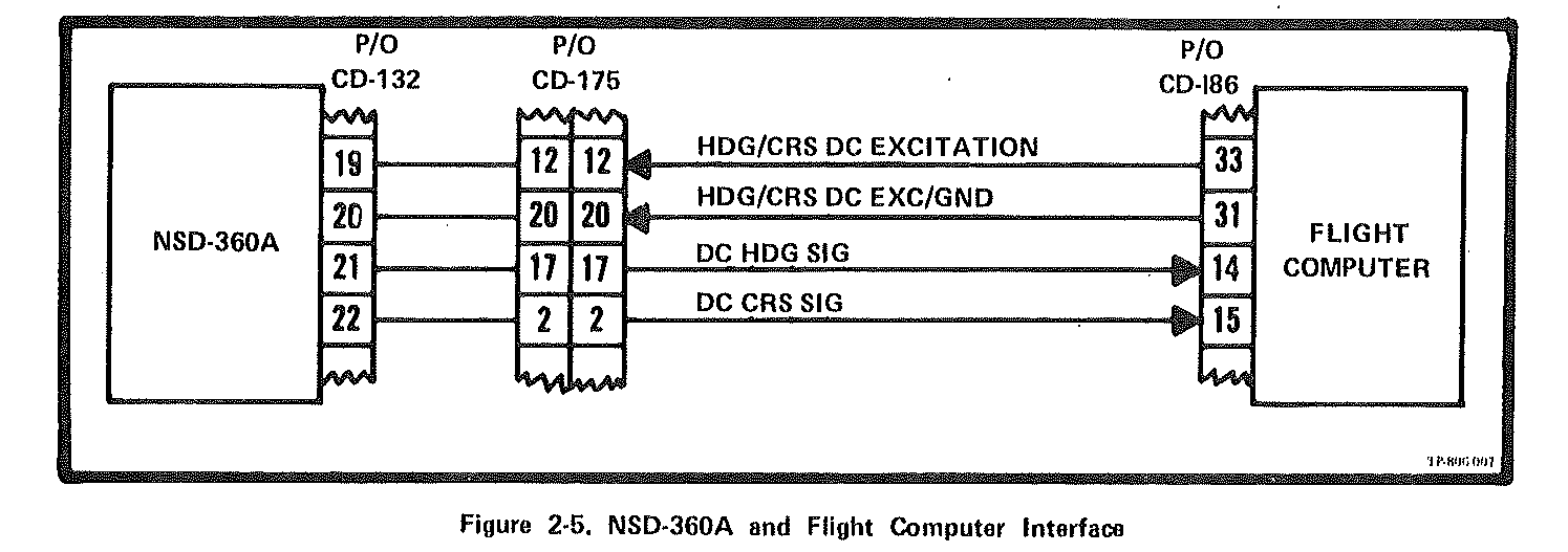
-
GI 275 /Century 21 - HDG mode fails after a while
Jake@BevanAviation replied to NicoN's topic in Avionics/Panel Discussion
@NicoN With the other lateral modes still working it shouldn't be a servo issue. You are down to checking the heading error from the GI275 for the C21 and possibly the IC's for signal processing inside the C21. Be very careful if you are going to open the unit as all boards are interconnected with ribbon cable that are known to cause issues. CD-175 would be the DG or HSI connector, CD-194 would be incoming power/ground, compass jumper select, and disconnect switch. CD-186 would be the connector at the back of the rack for the C21. What compass system did you replace with the GI-275? -
GI 275 /Century 21 - HDG mode fails after a while
Jake@BevanAviation replied to NicoN's topic in Avionics/Panel Discussion
Transformer isolation is not needed with the Century 21 system. -
GI 275 /Century 21 - HDG mode fails after a while
Jake@BevanAviation replied to NicoN's topic in Avionics/Panel Discussion
Odd question but when the system stop working and only does wings level have you ever tried to manual force the system off level and see if it returns to level flight? This would tell you a couple of things. The computer is still working for servo drive, attitude reference is still functional, and the roll servo is still responding to commands. The only thing you would be missing at that point is the heading bug error from the GI275. I am going to assume you don't have any messages on the GI275 indicating some type of heading failure. Also, when heading stops functioning have you tried to see if the other lateral control modes like NAV/APPR are functional? One last thing. Century used this analog gate IC's for signal routing and I have seen these become intermittent with time. Do you know if any of these IC's were replaced when the unit was worked on? Century P/N would be 48s114 or MC14016BCP. -
Garmin 430 repair rumors - Finally finished??
Jake@BevanAviation replied to Mark89114's topic in Avionics/Panel Discussion
I encourage anyone that has any issue with a GNS unit to please contact Bevan Aviation and talk to Mike or Zach to see if we can possibly repair the unit. -
King autopilot roll servo removal
Jake@BevanAviation replied to mooneyflyfast's topic in Avionics/Panel Discussion
@mooneyflyfast got the unit in today and have it fixed and ready to be shipped back. Give us a call when you are ready to issue payment. -
In some instances the KCS-55A system might have required a power inverter. See attachment for details. KCS-55A inverter.pdf
-
Century Trim Servo Motor Repair
Jake@BevanAviation replied to 231MJ's topic in Modern Mooney Discussion
Depending on the state of the armature wear specifically the commutator I might be able to fix it. If the commutator has excessive wear down to the insulator, the motor will need to be removed and sent to Globe for overhaul. I have new brushes and bearings but no new armatures.

