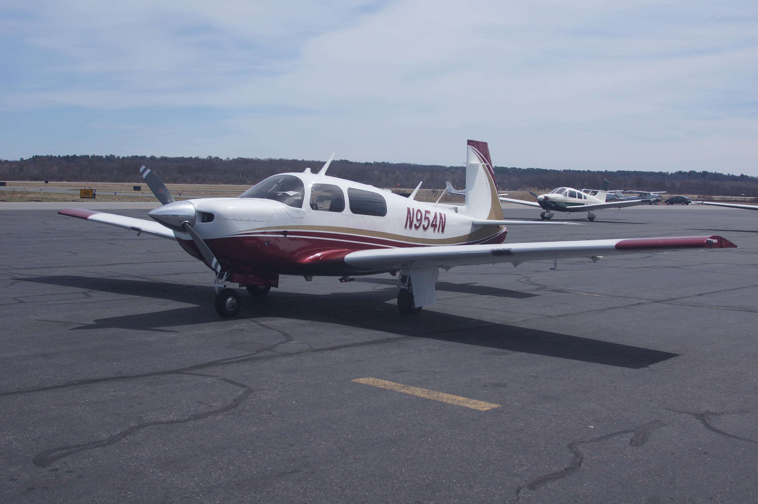
M20F-1968
-
Posts
1,846 -
Joined
-
Last visited
-
Days Won
3
Content Type
Profiles
Forums
Blogs
Gallery
Downloads
Media Demo
Events
Everything posted by M20F-1968
-

Foggy/muted wing taxi/landing lights lenses
M20F-1968 replied to PeterRus's topic in General Mooney Talk
Allow about 8 hours to fit both lenses (sounds like yours are wing-mounted lights). You will need a combination disk/belt sander bench-mounted machine - The Harbor Freight version will work. Also get countersinks from Aircraft Tools Co. They have fluteless countersinks that have a single hole in the side. The cutting edge is the single hole. They do not chatter and will safely cut without cracking. Work slowly with the sander to fit the lens in place, with sufficient play. It should not fit tightly. The holes for the screws will also be oversized. The screw heads will use couner-sinked washers. Do not use the aluminum frame. John Breda -
It doesn't matter as long as the thread type is proper, ande the screw (or likely machine screw) in long enough to easily reach the threds. What I dis, and the reason for my posting, his realize that the slot of the screw had is a PITA to access and engage with the 201 windshield and the height of my panel (which is an inch and a half higher than standard), I used a machine screw with a head that can be turned with either a socket wrench or ratcheting box wrench. This makes it a whole lot easier to take screws in and out and tighten them.. John Breda
-
I have some paperwork relative to the 201 conversion. John Breda
-
Do You Pull Obsolete Equipment or Leave it Be?
M20F-1968 replied to bigmo's topic in General Mooney Talk
All you need to do is build the panel supports with 1/4" aluminum bars into which screws could be placed to hold the trays, etc... in place. When you need to get back there, just disassemble what you need to gain access. That is how my panel was designed. The panel itself uses an instrument panel bow taken from an Ovation. John Breda -
Do You Pull Obsolete Equipment or Leave it Be?
M20F-1968 replied to bigmo's topic in General Mooney Talk
Weight is always a concern. Old wiring complicates future repairs. Unneeded wiring and equipment, should always be pulled before adding new stuff. It does make more work but it is proper to keep the plane current without complications. John Breda -
Have a 63 m20c that I’m scrapping/play forting
M20F-1968 replied to saltydecimator's topic in General Mooney Talk
And flap actuator. John Breda -
Have a 63 m20c that I’m scrapping/play forting
M20F-1968 replied to saltydecimator's topic in General Mooney Talk
What kind of fuel selector does it have? Is it an H&E. I am interested in it and the flap pump. John Breda -
As I recall, the Magic Arm came in two lengths. It has a threaded end which threads into the Super Clamp. Just but what seems right from a source that accepts returns (returnable e-bay merchant, Amazon, etc...) John Breda
-
Cigarette Lighter socket as USB power source
M20F-1968 replied to PeterRus's topic in General Mooney Talk
If you keep your eye out, you can find a USB panel mount unit in the $100-200 range. I found a used Stratus, 2 USB-B ports for $100 on ebay. The stratus needs only a proper hole size for the unit itself, no additional mounting holes (unit and face place hare sandwich the panel). Has worked fine. Prior to that, I had a cigarette lighter with an adapter which also worked without any radio interference. John Breda -
I retrofitted Ovation rear seats into my 1968 F model. In fact my entire interior came from a 1998 Ovation. John Breda
-
Baffling for a 1965 M20E
M20F-1968 replied to Bart Chilcott's topic in Vintage Mooneys (pre-J models)
Buy a bottle of machinist's dye, a new, sharp machinist's scriber. Trace the old parts, make heavy paper or poster-board weight cardboard templates. Leave a bit of extra material for and fitting with files and a dremel tool, and go at it. It is time consuming but you will get a better fit it you work slowly, and it will just cost you for the aluminum. Make it a bit heavier than the ones made commercially, probably 0.090". John Breda -
I promised pictures of the installation I use currently of my I-pad. After auditioning a bunch of Magic flexible arms, I settled on the Manfrotto Magic arm and super clamp. They are Italian made, and expensive, but much much better than their Chinese knock-offs. Also pictured is a cooling base which I just added. It needs the My-Go-Flight adapted. John Breda

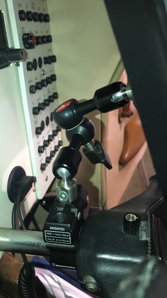


-
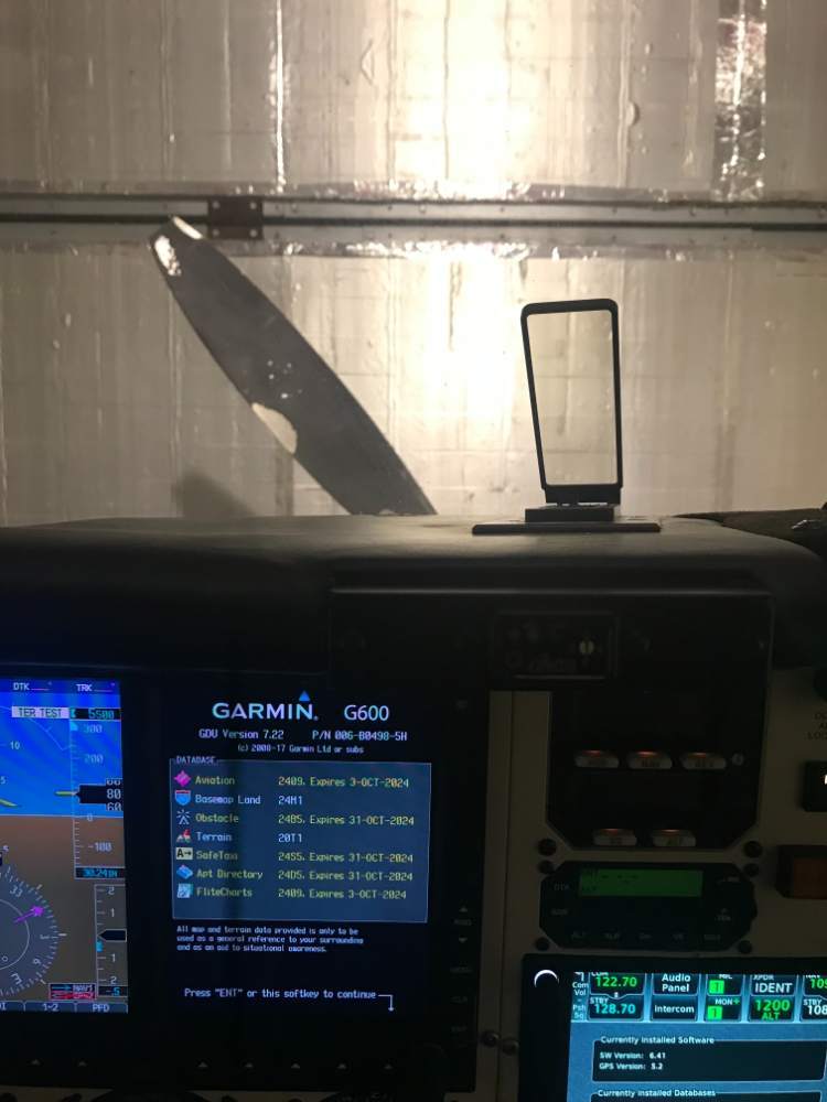
This is how my AOA is positioned. The post is just to the right, and the G600 is in the center of my vision straight out. Still need to shift my eyes to see the AOA. Alpha Systems wants it right in the straight-ahead visual field. How many of you have it straighht-ahead, and how many have it similarly placed to mine. What seems to be preferable? John Breda
-
Recognize the teflon seals you have are likely 60 years old. I am expecting to make some soon. I have been quite busy with some pressing deadlines. If you would like to be put on the list for some, PM me with your request, name, address, phone and e-mail. John Breda Cell (617) 877-0025
-
I am looking for a group response to this one. I installed the Alpha One with the HUD display just to the left of the steel tube, and slightly to the right of the forward straight-ahead visual path. It is turned very slightly so that the image (reflection of the unit itself) is centered in the HUD with only a small movement of the eyes needed to view it. I have a high panel (1 1/2" higher than most Ovations which was also used in the Bravo's for 2-3 years) so my visibility over the panel is less than most Mooneys. My parts were removed from a 1998 Ovation. I did not want to obstruct the straight-ahead view any further. Alpha Systems states that they install these units dead center in the forward view so you are forced to look through the unit. In what positions have others installed these units, how did it work out, and what is the consensus of the best installation in a Mooney? I have posted a picture of my installation below. I will try to get a couple of pictures from the pilot's seat. John Breda

-
There is an STC that I almost installed when I did my modifications. Not sure I have it in my documentation. I'm sure it would take some time to fined, but such a modification does exist. John Breda
-
Fur is not sewn with a typical sewing machine. A fur sewing machine is a small industrial sewing machine that make a running overlock stitch. The machines have an open architecture where the leather is placed together, fur facing fur, and held between two knurled disks that turn and advance the leather toward the next stitch. The machines are made in different models to accommodate the various thickness of hides to be sewn. Do a google search for Fur Sewing Machine and you will find some videos, used and new machines for sale. The older and quite viable machines were made in the 1930's - 1950's and were made in Germany, England, US, and elsewhere. Like with airplanes, you need to know what project you plan to do, since industrial sewing machines are made usually to make one type os stitch only, in one type or weight of fabric or leather. John Breda
-
I looked into this with Lycoming. Their specification is based on slippage of the belt measured with a torque wrench on the nut which holds the pulley onto the alternator. The specification is different for a new v. a minimally used belt. Belt tension is adjusted so that the belt slips at the appropriate torque setting. I have the specifications written down somewhere. Probably easier to call Lycoming or Continental and ask depending upon the engine you have.
-
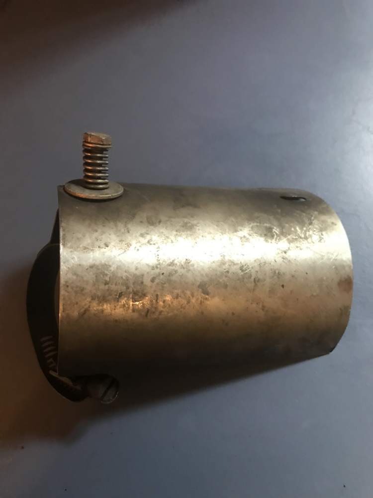
I have this heat shield, which is part of my turbo system, which is not made very well. The clamps keep cracking due as they are clamped onto the hot exhaust pipe, and the clamps used are thin. I've set out to try to make a more durable part. I purchased some 2-inch 304 stainless steel muffler clamps, which are designed for motorcycle mufflers. These have not arrived yet, but we'll see how good they are when I get them. I need someone who has the ability to weld 304 stainless steel. Can anyone assist? My cell phone number is 617-877-0025. You can also contact me here. John Breda


-
Is it Starter Replacement Time?
M20F-1968 replied to Igor_U's topic in Vintage Mooneys (pre-J models)
A year ago I had the pully on my alternator split in half. Turns out it was placed on the alternator ten years ago by an inept A&P in Dallas that I fired and sued. He still owes me a bunch of money on the lawsuit that I won. I thought I took apart everything he touched, but I missed the alternator pulley. It was an automative part. I replaced the pulley with a Hartzell Engine Products part, bought at Aircraft Spruce for $380.00. It is a very different part. Do not think automotive parts are adequate substitutes. John Breda -
I have been thinking of adding some sheepskin seat covers to my plane, but I do not like what is currently being made commercially. First, there is very little space between the outboard side of the seats and the side panels. It is sufficiently tight to make placing a layer of sheepskin there difficult. Secondly, I do not like the loose fit and the straps. What I envision is making a fitted leather seat cover tailored to the seat which slips over the seat. I have the Ovation seats so the seat bottom is its own piece velcroed to the aluminum seat bottom. I envision making a pouch that the seat bottom slides into. Likwise, the seat back will be fitted with a tailored cover that slides over the seat from the top, and has an opening in the back allowing access to the seat pocket. The face of the seat bottom and face of the seat back will be sheepskin, and the rest of the seat cover will be regular upholstery leather which will take up less room than the sheepskin because it has no fur, but is equally as durable. I purchased a fur sewing machine to specifically complete this task. Any ideas the crowd might add to the project? John Breda
-
I doubt your or any E is 156 kt airplane at 10,000 ft. A J with it cowling and windshield change is 160 kts. I suspect some manufacturer marketing tactics. John Breda
-
You do not have to remove the bottom cowling to change oil. Install a quick-release oil drain, and reach up inside the L cowl flap with a hose, slide it onto the quick drain, push up, 1/4 turn, and drain the oil. John Breda
-
Is it Starter Replacement Time?
M20F-1968 replied to Igor_U's topic in Vintage Mooneys (pre-J models)
Please disreragd my earlier post - I screwed up the explanatioin - so much for not proof-reading....... Here ity is again with the correct information. I have a Sky-Tec starter which I installed on my engine, and about 20 hours later decided to replace my left-sided engine baffling as I hava a J model air box and air filter which really needed a different baffle and an in-line starter. The starter I am selling replaced an 8 year old starterof the same type which stumbled a couple of times and I did not want to be left with a problem away from home. It is the direct replacement for your alternator on an IO-36--A1A. I have a 1968 F model, you have a 1967 F model, both with the same engine. Mine however is turbo-normalized and has a J model air box and J model cowling. I went for several years modifying my air filter by grinding it way to make room for the solenoid. I finally made a new left-side engine baffling which was correct for the J-model air filter. This has no side mounted solenoid to impinge upon the air filter area. I then replaced the 20 hour old starter which I am selling with an in-line starter which is what was needed for my installation with the J model air filter. The air filter now sits flat on the baffling without modifications. This process left me with an essentially new Sky-Tec 12LS, 12 volt starter which is pictured below. It will take care of your problems, is lighter, spins faster than what you have, and will be reliable since it is essentially new. I can sell it for much less than new. My cell is (617) 877-0025 and my e-mail is john.breda@gmail.com John Breda


-
Is it Starter Replacement Time?
M20F-1968 replied to Igor_U's topic in Vintage Mooneys (pre-J models)
I have a Sky-Tec starter which I installed on my engine, and about 209 hours later decided to replace my left-sided engine baffling as I hava a J model air box and air filter which really needed a different baffle and an in-line alternator. This is the replacement for your alternator on an IO-36--A1A. I have a 1968 F model, you have a 1967 F model, both with the same engine. Mine however is turbo-normalized and has a J model air box and J model cowling. I went for several years jerry-rigging the air filter until I made a new engine baffling on the air filter side. The alternator I am selling was swapped out after about 8 years after it stumbled once or twice. I replaced it with this one, and then shortly thereafter made a new engine baffling after my annual.The alternator pictured has 20 hours of flight time on it and is essentially new. It is a Sky-Tec 12LS, 12 volt. It will take care of your problems, is lighter, spins faster than what you have, and will be reliable since it is essentially new. I can sell it for much less than new. My cell is (617) 877-0025 and my e-mail is john.breda@gmail.com John Breda