

jamesm
-
Posts
892 -
Joined
-
Last visited
Content Type
Profiles
Forums
Blogs
Gallery
Downloads
Events
Store
Everything posted by jamesm
-
lasar/ mcfarlane throttle cable rigging
jamesm replied to jamesm's topic in Vintage Mooneys (pre-J models)
II know this question has probably been asked about weep hole. I know that I have replaced aluminum manifold pressure line from firewall to mechanical manifold pressure instrument. At least a couple times and never put the weep hole in line the mechanical manifold pressure gage line. It works fine. I now have EI CGR30 engine monitor It seems works fine best to my knowledge. It's has been 3 years or so. Is it necessary in digital manifold pressure transducer setup to have a weep hole? James -
lasar/ mcfarlane throttle cable rigging
jamesm replied to jamesm's topic in Vintage Mooneys (pre-J models)
If I am not mistaken on my setup '67C the weap hole is on the engine side on the after the adapter/coupler or in the adapter itself as it goes into the #3 cylinder prime port. I think might be 3/8" that gets reduced to 1/8" line then goes into firewall. It sure would be nice if EI made a manifold pressure transducer that could be mounted in the engine side of firewall. One less box on firewall cockpit area to find room for. I will have to check that out thanks. James -
lasar/ mcfarlane throttle cable rigging
jamesm replied to jamesm's topic in Vintage Mooneys (pre-J models)
Problem Solved... After thinking on it a bit. I had recalled that I had similar situation many years earlier. The problem is the the weather and my schedule hasn't align very well lately and when I did fly it was low level. The previously problem was about 15 years or so once that I realize the problem. Here is the scenario, when I climbed above about 2500 agl then the problem stuck out to me like a sore thumb, the Manifold pressure gauge act like an altimeter. As it turns out the manifold pressure line had leak and my brother had help me fix it. it could have been an ether a manifold pressure line leak or defective MP gauge. But I couldn't remember how we trouble shot the problem. When I had tried to fix the problem first time I was using vacuum hose with a reducer but the vacuum motors are way to noisy think I had tried can air whatever reason it didn't work at the time. My brother had reminded me that we had probably used a 200ML syringe to trouble shot the problem. With all new electronics added (CGR Engine monitor and SureFly Mag) I didn't want find out effect that the syringe might have on them. So I removed them from the circuit put this time I use a 500ML syringe while examining aluminum manifold pressure line it work harden on me and broke. So I ether had a piece of debris in the line or another line manifold aluminum leak. I rebuilt the aluminum manifold pressure line and I got to fly today and it worked great. Is there a company out there that make -2 hose for manifold pressure lines? instead of Aluminum -2 manifold pressure line. Most Hydraulic hoses go down to -3 that I have found. Thanks, James '67C -
Attitude Indicator and Directional Gyro faults
jamesm replied to Mooney-Shiner's topic in Vintage Mooneys (pre-J models)
Well with all the Aspen/Garmin/AV30/AV20/RCA electronic ADI HSI out there should be plenty of used /pre-owned Vacuum pumps, Vacuum regulators,and Vacuum driven ADI HSI, vacuum servo for the step to be had. James '67C -
You can get kind of funky readings from spark plug gasket type thermocouples for CHT's. i think they are low readings. the Insight G3 Graphic Engine Monitor GEM, had a special had a split bayonet mount and another connection was for the engine monitor thermocouples. If memory serves me correctly they were 20 to 30 degrees off. I eventually took the split thermocouple mount hooked the Insight probe directly into the Cylinder like all the other cylinders was more inline with the rest of cht's. Later on switch to CGR30 engine monitor using the insight thermocouples for my CHT;s and EGT's. Just because something is digital doesn't necessary mean that it is more accurate and you can loose accuracy by having a dual thermocouple setup on one cylinder. just my observations, James '67C
-
If it was working before ... what has changed? Do you have SD card in g5 and data recording enable? James '67C
-
I am a start / stop again instrument student and working becoming a start again instrument student maybe. For what it's worth I think at a minimum get left side shot gun panel layout cleaned up to a standard six pack layout. I believe Lasar not sure if they still them or not, Hendricks Manufacturing http://www.HendricksMfg.com/ and others out there will sell you a left side panel. Talk to your IA first see if they are willing to assist willing to allow you to do this. I get the the shot gun panel layout for VFR flying, since I had one for many years but for instrument training you will probably save time money and little frustration in the long run. So I would suggest on getting at least the left panel to standard 6 pack layout configuration. I am sure that you could learn in the shot panel layout configuration but if you ever decide to sell or rent or fly right seat someone else plane my guess it will transition a bit easier. since it one less thing to learn. Just my opinion hope this helps, James '67C
-
Instrument Placement Advice for a New Panel (yet another...)
jamesm replied to Seymour's topic in Avionics/Panel Discussion
This kind of a hotly debated topic around here whether autopilot control head is on the top or bottom of the stack. Just my personal opinion and preference why mine is on top of the stack. 1) Our older mid 60' model Mooney's have welded cluster at the top of the radio stack causing some dead space that can't be used for very much other than switches buttons something with shallow depth until go about 2" or so down the panel. then you start getting depth. I believe later model Mooney have offset the radio stack to avoid this problem and to maximize panel space. You can tell by relation between the Throttle / Mixture / Prop control placement versus the left edge of the radio stack. So probably not a problem if you are redoing the whole panel. which can added a bunch more cost. you can save if you find IA willing to do it under their supervision. 2) There is a potential vertigo trap having GMC507 (GFC Control Head) at the bottom of the stack. 3) The large Avionics and large Aerospace companies have invested tons of money into flight deck research in human factors when designing the first glass flight deck layout until now and for the future flight deck layout. This covers things such as to placement avionics, displays, switches, buttons and anything else that maybe on flight deck. While the large aerospace company can't agree on side stick or yoke for flight controls, they do agree on flight deck layout for the most part. They place the Autopilot at the top of stack. at least ones that I have seen. So far it works great, though I going through instrument training and may not be the best person to ask. Just look at other people flight deck pictures to what you like. Again just my opinion. Hope this helps. James '67C -
lasar/ mcfarlane throttle cable rigging
jamesm replied to jamesm's topic in Vintage Mooneys (pre-J models)
I will have to keep eye on it. I haven't seen it do the low rpm throttle position creep. -
Instrument Placement Advice for a New Panel (yet another...)
jamesm replied to Seymour's topic in Avionics/Panel Discussion
Something to think about, and just my opinion... I don't know that I would put the gmc507 (control head for GFC 500's autopilot) in the middle of the the avionics stack. since it's the shallowest in depth of all your avionics. Space maybe a challenge now and in the future avionics expansion I have a 67'C with 2 G5's gnc255 & gnc355 PMA8000bt Audio panel please excuse the picture crookedness and the not tighty glare shield just my opinion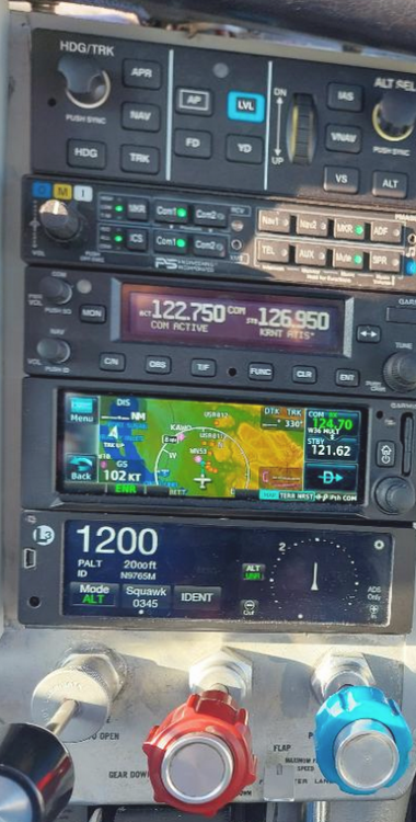
-
lasar/ mcfarlane throttle cable rigging
jamesm replied to jamesm's topic in Vintage Mooneys (pre-J models)
The throttle cable on my particular year and model of mooney. there is bracket comes from prop governor housing and then extends has I believe it's a AN742 clamp attaches to throttle cable sheve. -
Hi, I installed lasar Mcfarlane throttle cable in a 67C. The new throttle cable has the full range movement on the carburetor. The prop cable rigging never was touched and was fine the throttle cable was original 55 year old cable. When I flew it, I had full power on take off but in cruise when went to make adjustments with throttle and propeller my rpm dropped. for example anything below about 24" MAP , 2400 rpm my rpm will drop. In other words, I can't get 24^2 or 23^2 or 20" MAP 2300 rpm throttle/prop settings were done at approximately 2500 ft altitude. I was cross check the cruise setting listed in the owner manual aka POH. It was suggested to me to check my induction system for possible leaks, by backflow air through the carburetor air box. Then check for air leaks with either feeling for air or soapy water on induction joints and look for bubbles. I did a quick leak check today but didn't see any leaks but with a noisy air source it was hard to tell. Any ideas, James '67C
-
what part are you referring to ?
-
2 axis vs. 3 axis Autopilots for our Mooneys
jamesm replied to canamex's topic in Vintage Mooneys (pre-J models)
on my 'C' model with no yaw dampener, it has two circuit breakers "trim switch" and "autopilot". I am not sure if the yaw dampener has it own or not. -
2 axis vs. 3 axis Autopilots for our Mooneys
jamesm replied to canamex's topic in Vintage Mooneys (pre-J models)
With GFC500 you could install the yaw dampener later it's bracketed allows for it and since it use CAN all would have to do run power set of wires to Yaw dampener servo to have it installed at later date. -
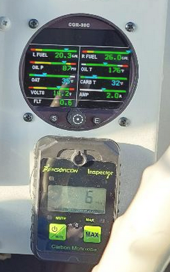
I just built aluminum hanger goes between 2.25" instrument hole that uses those screws. then mounted the detector using the screw normally use to hold the clip.
-
Ain't that the truth. I had bought set of hoses from a supposedly well respected hose manufacture, I bought during my engine overhaul several years go thinking that it should fit. since they sell them as kit for my model and year Mooney and supposedly had gotten the sizes from Mooney . But when it came to installation one of the hoses wouldn't fit. So I called them for a refund I told them they reuse the fittings on someone else hoses but I got stuck with only half what I should have been refunded. I the past I would send my hoses to Sacramento Sky Ranch John and the crew always did me right. Not sure if they are still around. I know His books are still in print. Very well written in my opinion.
-
Throttle - don't let friction go unattended
jamesm replied to Boilermonkey's topic in Vintage Mooneys (pre-J models)
also watch the other end the Throttle cable where it mounts to bracket (aluminum angle) coming off the prop governor (oil pump) held on by AN742-x metal clamp. that can slip allowing partial power on landing. Later I realize that other Mooney's of the same vintage had cross wrapping the throttle cable sheath ( housing) with safety wire to prevent the throttle cable sheath from slipping in the AN742 clamp. -
8 Zircs per main gear; I don't believe you ;)
jamesm replied to TheTurtle's topic in Vintage Mooneys (pre-J models)
is there a web site / email address for these ? Thanks, James -
8 Zircs per main gear; I don't believe you ;)
jamesm replied to TheTurtle's topic in Vintage Mooneys (pre-J models)
is that a 45degree in the 4th picture down zerk ? or is it bent or ??? Having a 45 degree is cheating. -
I think I need a breaker/switch...
jamesm replied to Nukemzzz's topic in Vintage Mooneys (pre-J models)
If they align up right you might get a with a replacement. Some time the potential replacement switch/breaker might not align with electrical bus bar so then you may have redesign/rework to get it to fit which could be considered as major alteration by some. Years ago I had the old Circuit Breaker (the red button type) on the right side fail on me. the replacement circuit breaker had "Line" and "Load" terminals reversed from the original circuit breaker. Not knowing the inner working of that particular that circuit breaker I mounted it upside down. WIth the Klixon 7270-x circuit breaker being almost $180.00 per breaker and perhaps a suitable substitution Tyco Circuit Breaker W31X2M1G-XX Series being about $40 - $44 per breaker So how would you interpret this from Tyco's Literature regarding W31X2M1G-XX Series Circuit breaker "0.5 amp to 50 amp ratings may be used as on/off switch." Could this be consider as a suitable substitution in the eyes of the FAA? or is there more to it that I am not seeing ? Ask for a friend James '67C tycoBreakers(1).pdf klixon7270_7271(original_left_side_sw).pdf -
head phone / micro phone location on panel
jamesm replied to jamesm's topic in Avionics/Panel Discussion
I makes me a little nervous being that the starter button is exposed there is no switch guard for it. It takes a little of pressure before the switch will engage the stater but I pull the circuit breaker while the plane is in the hangar as a safety measure. -
head phone / micro phone location on panel
jamesm replied to jamesm's topic in Avionics/Panel Discussion
Hi, I am attaching photo which I hope explains better on what I am thinking. the proposed right side photo is just tape on for a proximity location. Note: I had temporarily taped up the "previous location" head/micro phone to give position as a reference only. as mentioned before the "previous location" work ok until one flight I move knee suddenly and slightly bent head/micro phone plugs. so I moved the jack up to the "current location". I think the head/micro phone cord should be plenty long enough. I have upgraded my upholstery with Jaeger interior several years back no more ash tray. I could side mount head/micro phone housing but if it is over by the pilot's elbow I would have to extend or remake head/micro phone audio cables going to the audio panel. The other thing is the side panel by the pilot's elbow comes frequently during annual and cable routing so I would have to disconnect and reconnect head/micro phone cabling which could potentially cause maintenance induced maintenance problem. Thanks for the photos and illustrations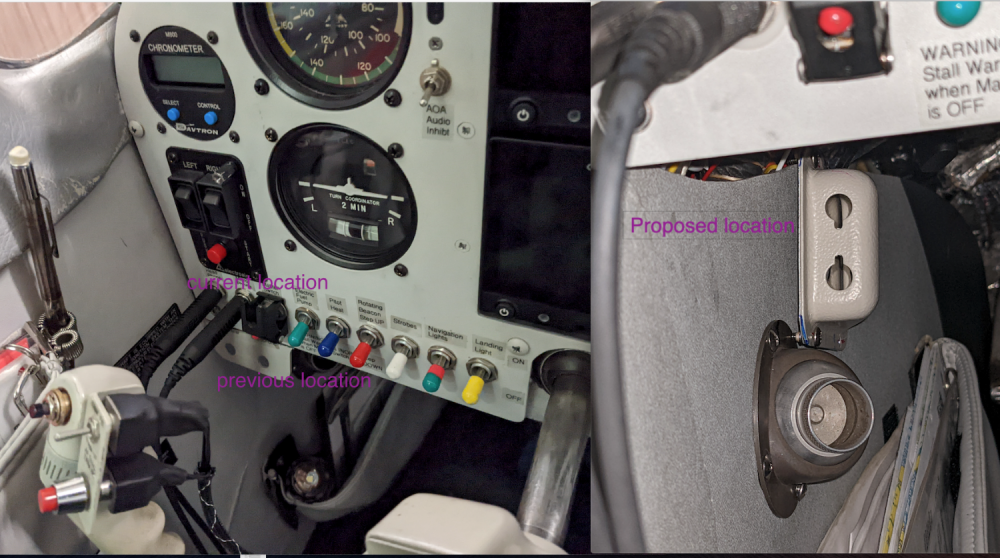
-
I have run out room on the left side panel for any more switches and was thinking of relocating the headphone& microphone jacks to recoup room for two more switches. In past had experimented having extend panel maybe a 1.5" from the bottom row of switches. It worked ok until one day I move left knee really quickly and it bend the head phone/micro phone plug. The plugs were only slightly bent and still worked but decided that wasn't the best location for the headphone& microphone jacks. so I moved the jacks back to panel with all the row switches just above tubular structure. I am curious to know if others tried different headphone/microphone locations other than just above standard bottom row switches in Mid 60's C model Mooney. Since I very rarely unplug my headset and microphone jacks other annual or to work on the panel. I was thinking of relocating headset and microphone jacks further down the foot well maybe near the pilot;s left knee behind the air vent. I think this location would be within reach should I need to switch out headset inflight. I have already filled the area below the cowl flap knob near the pilot's right knee with USB ports charging and EI engine monitor data ports and landing light flasher and alternate static port pneumatic switch. there is no more room at this location. I was trying for natural flow location for the switches and trying to avoid the random switch location that may have been an after thought where you see a switch in the middle of no where on the panel look. Curious to know your thoughts ? Thanks James '67C
-
Crankcase Breather Tube Position for a ‘66 E
jamesm replied to Yourpilotincommand's topic in Vintage Mooneys (pre-J models)
I have been experimenting with mine. I want to see if increasing the length that is expose out in the slip stream will keep the oil off the belly.


