

Marc_B
-
Posts
1,314 -
Joined
-
Last visited
-
Days Won
10
Content Type
Profiles
Forums
Blogs
Gallery
Downloads
Events
Store
Everything posted by Marc_B
-
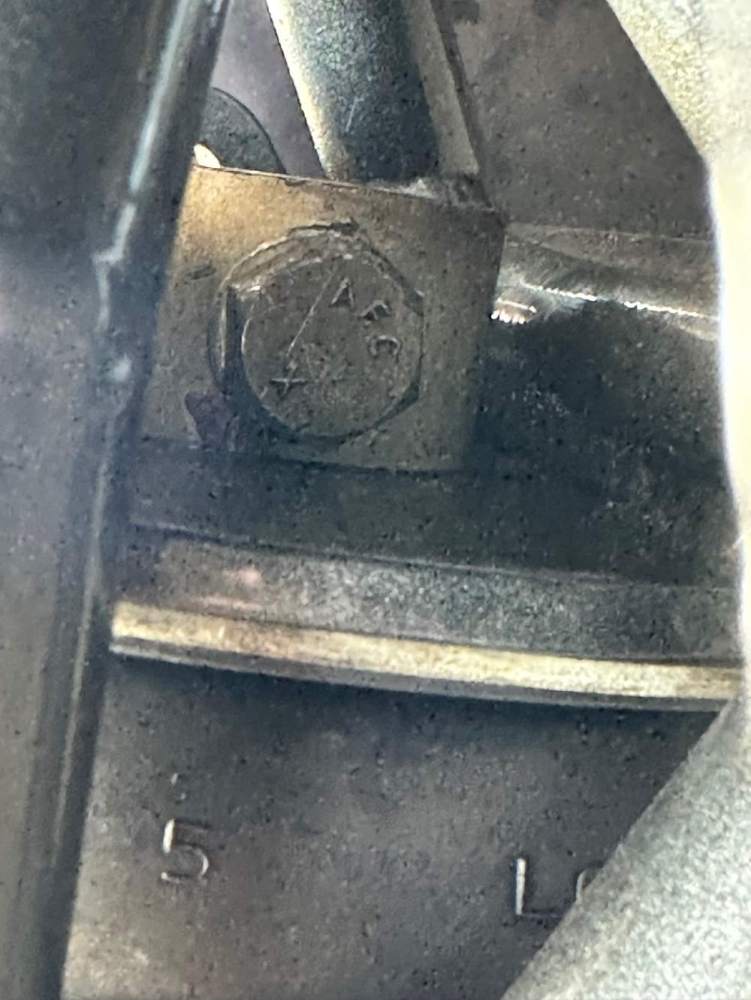
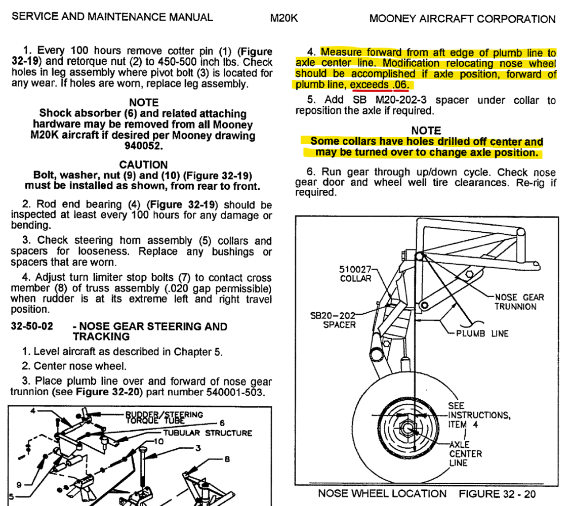
Collar thick side up. We had to flip this over to get fore aft position aligned. Thick side down (or add a shim) moves the nose wheel aft.
-
I know when I had the nose gear discs replaced it made a considerable difference requiring the collar to be flipped from the old position (thick side up) to now being "thick side down." So you have different settings to get geometry set: collar thick side up, collar thick side down +/- the shim/spacer. From what I'm told, the material these days is less compressible so that probably accounts for needing more stack "squish" to get it set for proper fore- aft-position.
-
@tpreece
-
-
GTN 650Xi Auto Switch and GFC 500 ROL reversion
Marc_B replied to PT20J's topic in Avionics/Panel Discussion
I think that would depend on when you pressed APR. When I let the AP do it's thing, I find that it switches CDI when the waypoint sequences to the leg leading to the FAF and about 1 dot outside of course; as soon as the CDI switches LOC becomes active.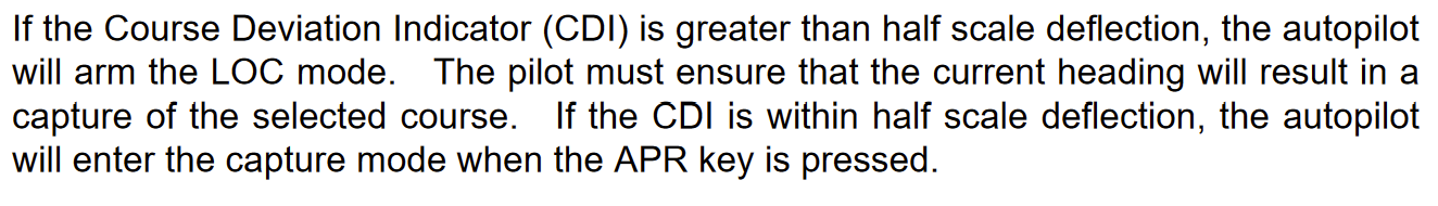
-
@BageMooney You might reach out to @Vance Harral, he’s based there and might have connections. Or reach out to Rocky Mountain Aircraft Services close by; they service quite a few local Mooneys. http://www.rockymountainaircraftservices.com
-
GTN 650Xi Auto Switch and GFC 500 ROL reversion
Marc_B replied to PT20J's topic in Avionics/Panel Discussion
If ATC has you vectored and is telling you they are gonna have to fly you through the localizer for spacing, make sure LOC is not armed (APR). If it’s armed it will auto switch and capture the LOC turning inbound. If you have APR armed, just press the APR button again and it will turn off. Edit: @ArtVandelay if you're being vectored, I take it that you're in HDG mode and a CDI switch won't matter. However if you're in GPS mode coming in a feeder route, then you need to switch to HDG mode prior to the CDI switch or GPS turn inbound...GPS + CDI switch = mode reversion. -
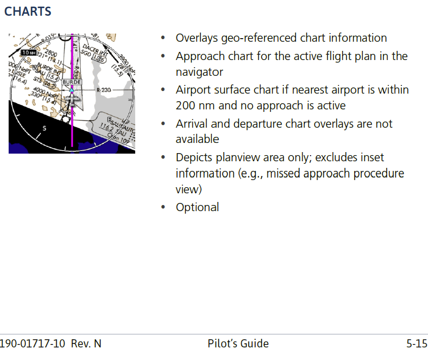
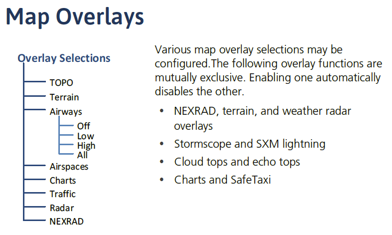
@PT20J I don't think so...but I'll have to take a look....I don't find anything about changing opacity in the pilot guide though. The way I understood it was that the various overlays were just fixed settings and some of them are mutually exclusive...and it's interesting that it's not the entire chart either...just plan view (on the G500TXi). So even in North up (or trying to get chart normally oriented) you couldn't use it for briefing...that's why I like the Aera (or iPad if using that) and just go to expanded chart quickly for brief and info. You can pull up the full chart ("Charts") on the GTN as well as the MFD on the G500, but I don't think they are as readable and easy to use as the Aera (or iPad). YMMV.
-
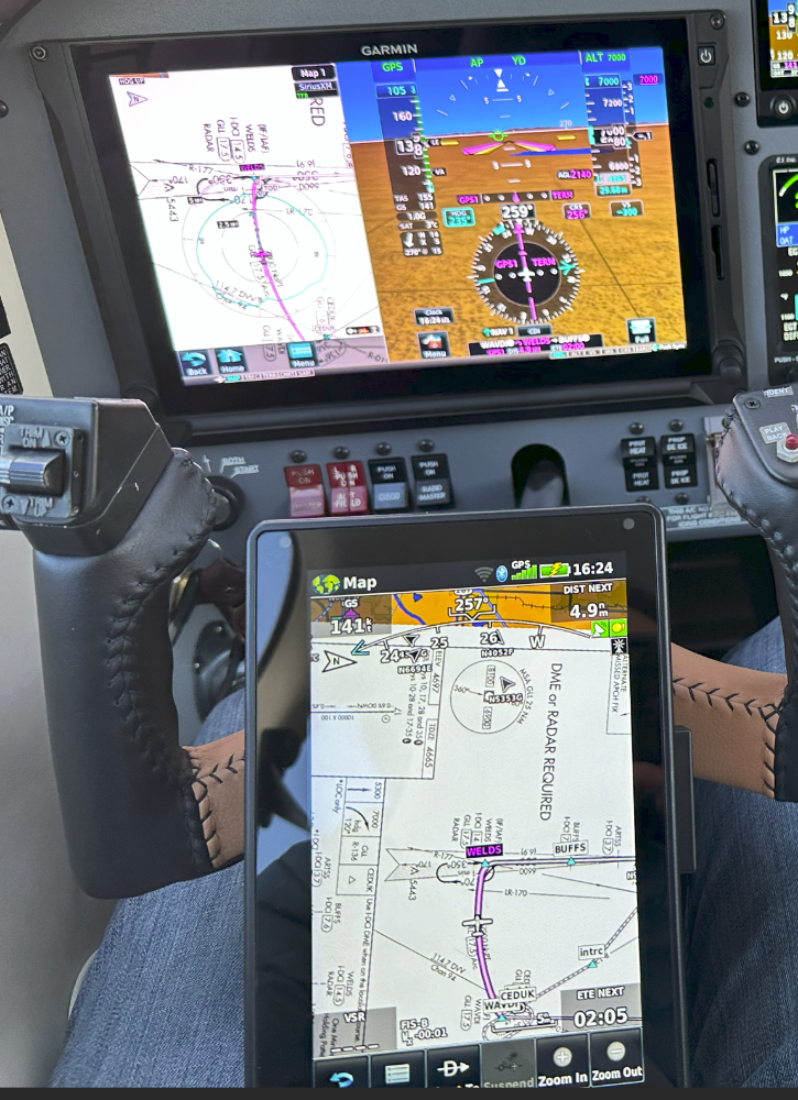
Had to look though my pics to see if I had one that had chart overlay showing; not the best pic but can get the gist. It also shows them zoomed so you can see the difference between sharpness of the background chart comparison...TXi not as sharp but certainly readable. I find that I don't use chart overlay on the GTN at all as it seems not very functional and keeps a screen with standard map available. But I've turned on chart overlay on the G500TXi and now also have turned on "All" altitude constraints to show on the TXi (on the GTN I set "Active & Selected Altitude" constraints on). But Don is right, the Aera or my iPad is a much better place to zoom in and do an approach chart brief...but for that I actually go to charts.
-
I’ve always wondered why don’t the Garmin units have map layer more akin to geo referenced VFR sectional charts? ForeFlight has the ability to overlay Terminal charts and has the detail of sectional charts as a layer. But I’ve not seen that quite the same with G500, TXi, GTN or Xi. Not sure if it’s different in the G3X?
-
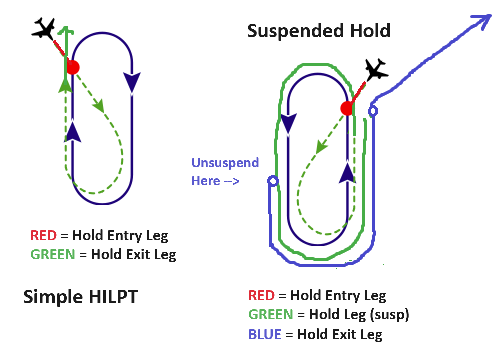
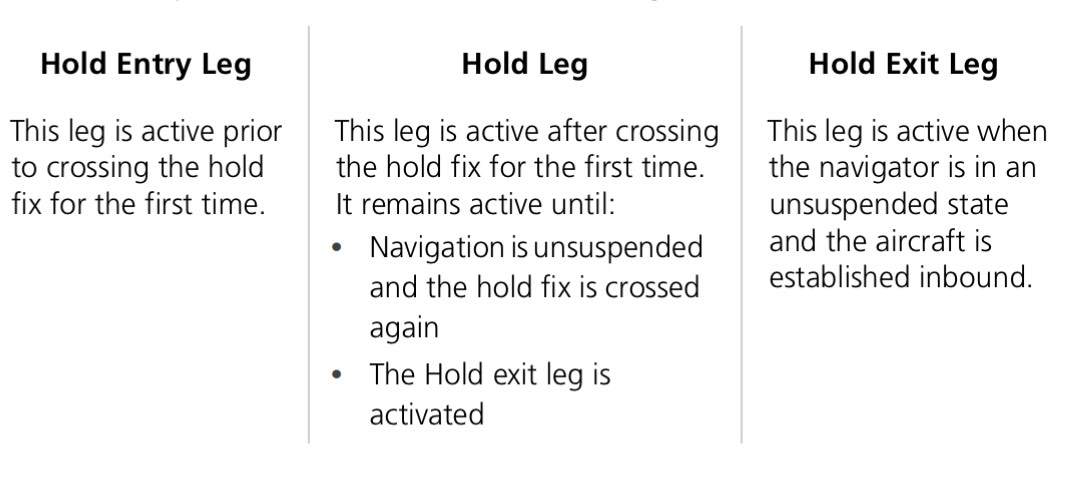
I think the easiest way to think about this is figure out Garmin logic and definitions. Basically a Hold Entry Leg and a Hold Exit Leg can have an altitude constraint added to the flight plan and VNAV can use these for vertical sequencing. So for a simple HILPT it's works. However with a Suspended Hold, that adds a "Hold Leg" (shown in the pilot guide graphic a few posts up) that will circle indefinitely in the hold until unsuspended, and VNAV will no longer be available for vertical navigation. HOWEVER, when you press UNSUSP, it then sequences a variable length "Hold Exit Leg" that can then resume VNAV. But depending on when you unsuspend the hold, the total length of the Exit leg could be anything from essentially an entire loop in the hold to a tiny segment if you unsuspended right before the fix. So you can't always count on the Exit Leg altitude constraint unless you plan appropriately. My thought is that if you're given a "Hold at X and descend and maintain 2000 feet in the hold" then you'd be better off using VS and your altitude bug.
-
Back course and VOR you can't use autoswitch CDI. Back course, VOR, and LOC you don't use APR. Without a proper mode armed, a change in CDI causes mode reversion with GFC500. I don't fly LOC, VOR, or BC frequently enough to feel solid on the gotchas in these approaches.
-
So I think the LOC/GS armed in white is what avoids autopilot mode reversion. You can arm LOC course by either pressing APR (which also arms GS) or by pressing NAV which just arms LOC. But it would seem that if you don't have LOC armed and your CDI switches then you'll revert to ROL PIT. I'll have to take a flight and go though Localizer only approaches. Haven't done those in a while. Certainly in HDG mode you could press NAV and arm LOC?...but what if you're on a feeder route in GPS...do you press NAV again to arm LOC?
-
@PT20J The thing that made me think that APR is what prevents the mode reversion, is that if I load an ILS approach, am in NAV mode on a feeder route and forget to press APR on the GFC500, then it will revert to ROL PIT when I switch the CDI (or when CDI switches automatically) coming up to LOC course intercept. It will blow right though the LOC. This I know for sure. If a LOC approach is loaded and it is left in NAV, would that prevent reversion?? Not sure. But I think that it also depends on if the LOC course is armed...i.e. when you press APR it arms LOC in white. From the AFMS it says press NAV key and verify LOC armed for a localizer approach. So is it LOC is armed that prevents reversion or APR is armed? But I don't find that the Aviation Trainer reflects the actual behavior of the GFC500 with this very well.
-
So Hold entry leg allows a constraint and hold exit leg allows a constraint. I think a HILPT just has a hold entry leg and a hold exit leg so the constraints/VNAV sequences...my perception of the slide shown at Garmin (comments above) was that VNAV unavailable with hold leg/suspended hold. "Heading legs" and "altitude terminating legs" I've seen programed with missed approaches and with departure procedures. I've never seen a way to program these myself. But both of these would be typically seen with climbing, and not with descents; Garmin definitely pointed out that the VNAV is an enhanced descent mode only.
-
I think the clarification is that an altitude constraint to enter a hold is okay. But I’m not aware of the GTN/GFC500 being able to make VNAV descent in a hold. If it’s a HILPT into an approach that’s not quite the same thing. VNAV will allow program of altitude constraint into the hold entry fix. But say you’re at 16,000 and you get “descend at pilot’s discretion, cross Waypoint A at 10,000 and descend in hold to 2000, then proceed to Waypoint B” I don’t think VNAV will do it. It will cross at 10,000 and then you’ll have to manage VS and bugged descent yourself inside the hold. I think it all depends on what hold “leg” is active. A hold entry leg has a constraint and you can use VNAV. Inside the hold (hold leg) does not from my understanding (i.e. when hold suspended and you're circling). The Garmin Trainer allows entry of an altitude constraint for the entry waypoint and for the exit waypoint. But it only descends when unsuspended. @PT20J & @donkaye Are you saying you are able to program a start hold constraint as well as a finish hold constraint to descend using VNAV inside the hold (while suspended)? VNAV is only for descent and the missed approach wouldn’t be VNAV but rather climbing. Sure, you can still plug in altitude constraints in your flight plan page, but that’s not VNAV. I set up the GTN to show active and selected constraints on the map in settings and show all constraints on the map on the G500TXi. Then you can easily see constraints coming up as well as using the Baro Minimums bug at times for an altitude bug for climbing (i.e. say on an ODP when you don’t wanna turn before “x” feet)
-
@donkaye it could all be just a matter of certification…not sure. But it sounds like Garmin teams are fairly siloed so hard to say what a different team is seeing or working on.
-
The training crew did mention that part of the issue with Transition to Approach is with extreme temp that the fixed glide path intercept may not be the same as the baro FAF so there may be a discrepancy that causes an issue. Made it sound like issue is matching up VNAV path to the GP to intercept smoothly is the issue.
-
A few VNAV limitations from Garmin I learned at training class… VNAV is unavailable if: -meeting the constraint requires a climb; -meeting constraint requires aircraft to exceed max FPA (6deg down) or max VS (4000 FPM); -it results in TOD behind the current position; -it is within a leg that does not support altitude constraints (holds, heading legs, altitude terminating legs); -it is for a waypoint past the FAF. Of course you first need to have all the basics met that are listed in the pilot guide… Enhanced VNAV will not function if any of the following conditions are true: - Navigation source is not set to GPS - VNAV not enabled on VNAV profile page - No waypoints exist in the flight plan with appropriate altitude constraints - Lateral mode is not actively engaged to GPS - OBS mode is active - Dead reckoning mode is active - Parallel Track is active - Aircraft is on the ground - Aircraft is between the FAF and MAP of an approach. I find it strange that VNAV won’t work on GPS parallel track. Seems like it should be able to. The others seem pretty straightforward and obvious after some experience with it. Still no update regarding Transition to Approach. Of course the training team and development team are different so hard to say if this is in the works or not.
-
It looks like the erroneous settings were just "removed" from the visor in the original picture!
-
Surely there is a company that will create a decal for this. I've seen decals that have a clear backing you remove and you lay the decal down with a clear mask, then remove the mask leaving the labeling. I'm not quite sure what this is called...labeling, screen printing...or just a vinyl decal?
-
The only issue with the screw in lead plate is that it is thicker (taller?) due to the screw in leads and has more clearance issues in some applications. So double check your clearance before going that way to confirm you’re good to go. i went with Maggie when I installed a Surefly and have been happy.
-
M20J - All Annunciators Illuminated
Marc_B replied to WheelPantsOff's topic in Modern Mooney Discussion
I ran into some annunciator issues with an install, but this was with new circuitry and it was some miss mapped pins. Long story short, the Test + and Test - pins on the back of the annunciator are for bench testing only. They should not be connected to power or ground. The electrical schematic for your aircraft will have the pin out for your unit. This doesn't necessarily match another Mooney model or even same Mooney but different SN range. So you need to pull the schematic for your SN. You'll notice on my schematic below that pins 4 and 14 aren't connected to anything in the ship and it should stay that way. If power was connected here and it fried the test circuit then you might need to send it back to IAI if you still have problems with the test button not working or working erratically. The test button should be just a momentary switch to connect bus voltage though the lights to validate that they all illuminate. Most of the circuitry isn't spelled out in the MSM as it only discusses the more complicated circuits. Quite a few of the indications are what Mooney called a Typical Positive Apply. Basically it just illuminated when aircraft voltage applied (in my case +28VDC) to the pin. This applies to many of them like boost pump, speed brake, stand by vacuum, prop deice, etc. The fuel comparator circuits are the more complex inside the annunciator and you'll find a description of those in the MSM. If you're continuing to have issues I'd reach out to International Avionics, Inc in Richardson, TX. The person I worked with was Kenneth Snowden; main number 972/417-2820. Annunciator_MooneyServiceManual.pdf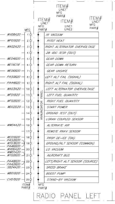
-
Let the games begin - MAJOR Avionics Upgrade.
Marc_B replied to Pinecone's topic in Avionics/Panel Discussion
You could either have a custom piece made out of plastic, modify your existing, or call IAI and ask for a custom legend. Its basically a piece of clear plastic in two layers that has holes on the ends that accept the male post that screw the unit to the panel from behind. When you look close it's actually roughly done and basically a colored label that each light shines through...cut and stick. (SEE MY PIC EARLIER ON THE PAGE and you can see how each indication was a cut out) Given that LASAR sells the legends separate from the one and two row annunciators, I would imagine that IAI could easily make you a legend to your spec. All of the indication lights are simple white incandescent bulbs. The person I spoke with at International Avionics, Inc. was Kenneth Snowden; the main number 972/417-2820 if you go that route. Kenneth also services IAI voltage regulators found in a handful of Mooneys. DMax said if it was labeled IAI it needed to be sent back to IAI, so I did that at the same time as the annunciator (mine was overvolts and needed to be adjusted). -
Speedbrake does not fully retract
Marc_B replied to Fritz Kaiser's topic in Modern Mooney Discussion
Looking at the pictures of the units...can these be lubricated while installed? It seems that the worm gear may be more accessible from the top? Although I keep thinking that I've read that it's accessible from the bottom access panel and a long brush/stick applicator? Does anyone have any tips or tricks? Certainly if removed they look super easy to clean and lube.
