211º
-
Posts
399 -
Joined
-
Last visited
-
Days Won
1
Content Type
Profiles
Forums
Blogs
Gallery
Downloads
Media Demo
Events
Everything posted by 211º
-
That is a good read. Thanks much. I also appreciated seeing the photo with slivers in it - lots of slivers - just as a comparison of how bad it could be.
-
I've always thought that (for the most part) flecks are (relatively speaking) normal wear and tear - unless there is an amount that could be seen/gathered in a teaspoon. And slivers are pieces of metal being shaved (stripped?) from the cam-shaft and indicate that the cams are getting past the very hard (and thin) protective metal/layer. I'm open to hearing more/other opinions.
-
My wife gave me a GoPro for my birthday... so I've been making some videos. This short-ish video shows what I do once I get the actual filter out of the filter casing.
-
@Lawyerpilot, the poor-man's way to check PC and Autopilot systems (maybe you have a tweaked system that uses different parts - it seems that there was a lot of transition between 65-66-67 production. PC System: when taxiing, push one rudder, the aileron/yoke should deflect in the other direction. If it moves in one direction or the other only, that is a pretty good sign as it implies that the PC system is working but that there is probably a vacuum leak somewhere. Autopilot: On the ground when the aircraft is running and vacuum is flowing (maybe a little higher than 1300 on the RPM), turn the auto pilot to Heading and turn the heading bug on the BI-603 to 90° left and right of the direction that your plane is facing. If the autopilot is working, it'll deflect the ailerons/yoke toward the heading direction.
-
@Lawyerpilot, regarding the BI-603 and checking its operation, see the attached Brittain document 11968-1. (FYI, there is also a 11968-2 document that has to do with altitude control - the document naming convention was a bit confusing to me as initially I thought that "-2" was a revision of "-1". I've also attached the "base document" 11968 that has to do with just the PC system. Finally, I've attached the 11971-9 document as it shows the entire B-6 installation (I think our installations are (if I recall correctly) the B-2B installation, but they are very similar - I think the the only difference is that we don't have the eye-ball leveler in our BI-603 unit - it is blanked out. MM 11968-1 Mooney Nav-Coupler-Heading Lock Operation and Service Instructions.pdf MM 11968-2 Mooney Pitch Control Operation and Service Instructions.pdf MM 11968 Mooney PC Operation and Service Instructions.pdf 11971-9 Brittain B6 Installation Instructions coloredIn.pdf
-
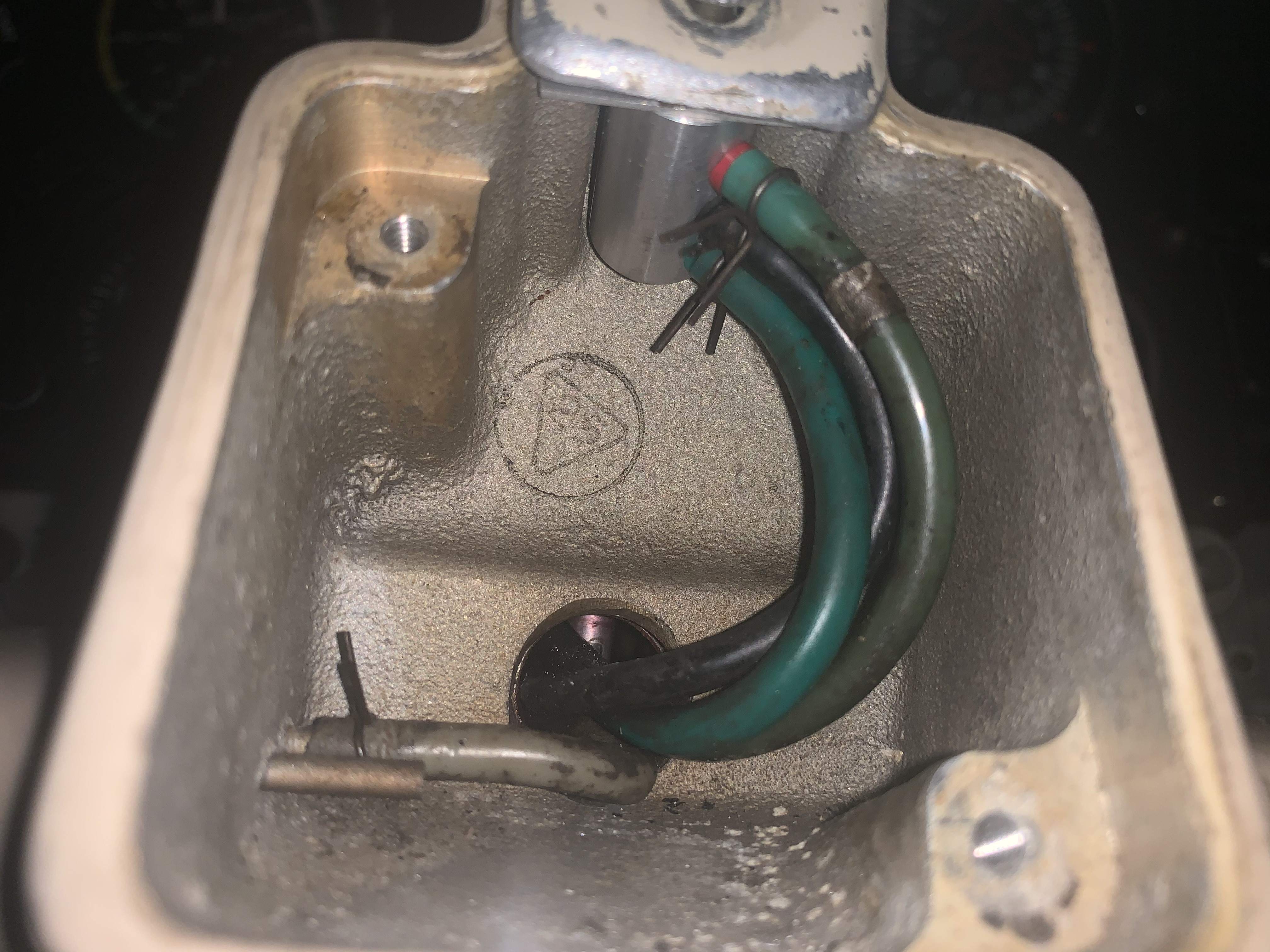
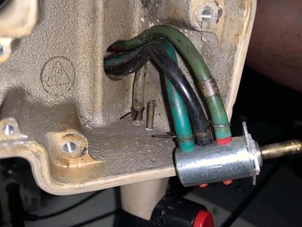
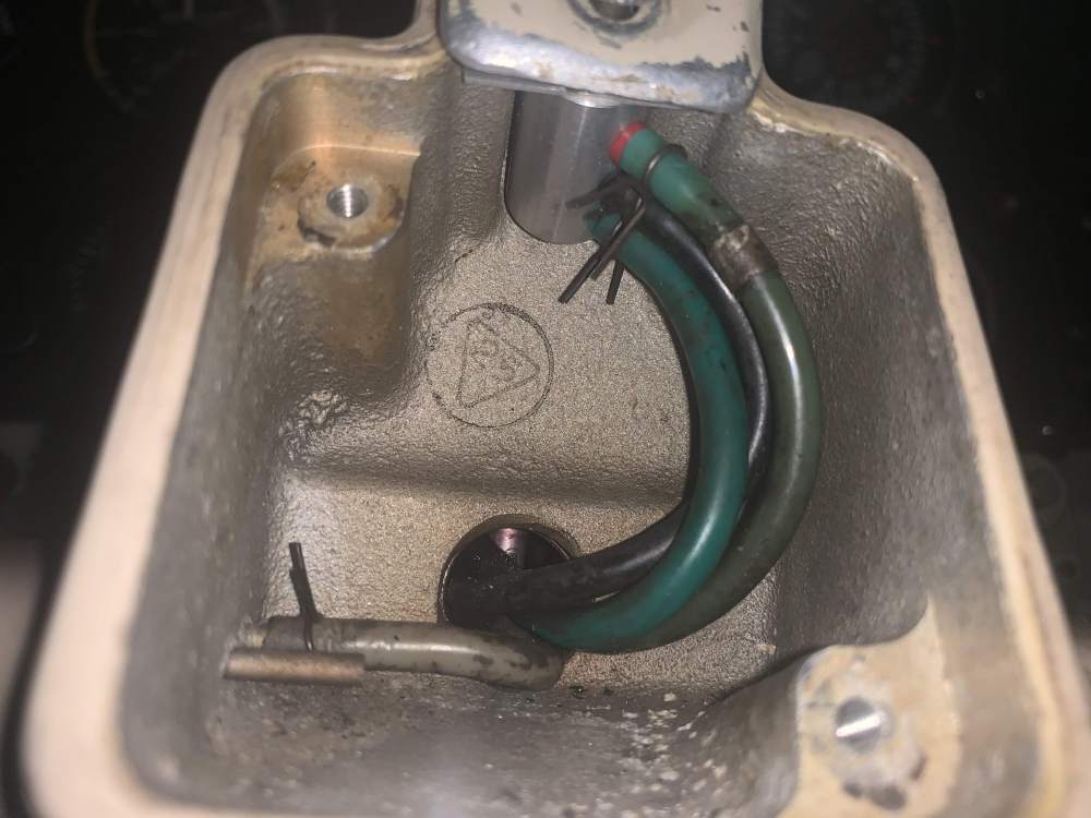
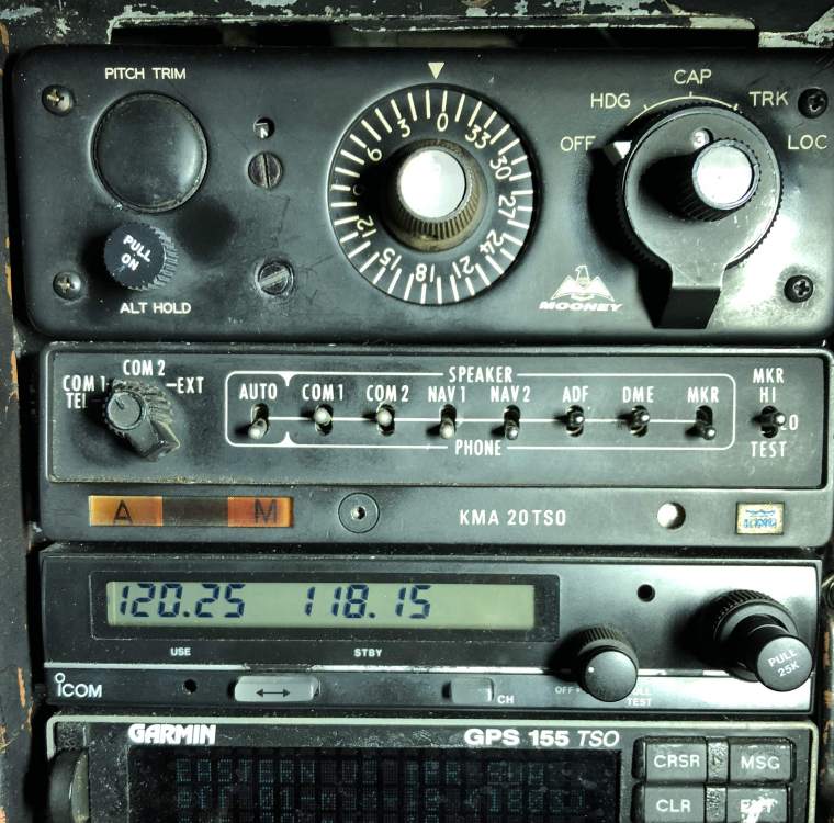
@Lawyerpilot, I am editing this on the fly a bit and hope that it'll make sense. The first thing that would have helped me a ton is to think of the Positive Control system and the autopilot system (the BI-603 and its components) as two separate systems. If you can get the PC system to work, you will have the "poor man's autopilot" system working... and that will create the your first smile as that system does a pretty good job at reducing pilot workload and confirming wing leveling in IFR conditions). Once you get that working, then as you move on to the checking the actual autopilot, you'll get a bigger smile as (say) you get even just the heading function to work). I think that you and I have the same system for direction control - my BI-603 has a pull-button for altitude control too (but that is just a pneumatic switch (no electronics). Autopilot: I think that I have a manual to check the BI-603 to make sure that it is receiving power and is in working order - it involves sliding the unit out a little bit and then checking voltages while in different autopilot configurations and/or using the heading bug. PC System: I think that you were the person asking about directional control - there is a "roll trim" button above the clock on the yoke that balances the aileron input from side to side to compensate for passengers or asymmetrical fuel loading/use. I'll find and post a photo of mine. I've heard that some units also have this mounted on the panel. PC System: Also on the yoke, you should have a pressure relief button on the left hand side. If/when you open the clock panel on the yoke, there should be four 3/16" vacuum tubes. One goes to the pressure relief button and three go to the roll trim button. (on the pressure relief side, one of the nipples doesn't have a hose attached to it - it is an open air line. I'm guessing that this is where the pressure/vacuum relief air comes from). PC System: About your photo with the two Ts and the red and green lines going to them, if we talk about just (say) the red line. From that T, one red line goes all of the way back to the ailerons (ultimately the left wing) and rudder servo (there is another T here at the baggage area). Attach the vacuum tester here (at the front T area) to this line to check a whole part of the system (not just the vacuum hose from the baggage area to the aileron and its servo) but (a) the red vacuum line left of the pilot behind the side panel, (b) the T at the baggage area, (c) the line from the baggage area to the rudder servo, (d) the rudder servo, (e) the line from the T to the aileron, and (f) the aileron servo. If you can hold 5 psi, you have much of your path solved. PC System: A second line from that T goes to the Pilot Valve (I don't know what this valve does, but a line goes there). PC System: The third line goes to the Rate Gyro (not the Remote Gyro). This Rate Gyro also has an adjustable "stem" on it that can balance the vacuum system between left-level-right (10" Hg - 0" - 10" Hg). This stem is not adjustable in flight or with any frequency as it is Allen-wrench tightened. I'll find a photo of mine looking up from near the rudder pedals (my hunch is that you may be missing this piece). Dave PS: I may have portions of this wrong, I'm a guy trying to pay it forward as Mooneyspace helped me learn about and tweak the systems over the years. As @carusoam frequently states "Dammit Jim, I'm a pilot not an airplane mechanic" - or at least I hear that every time he adds his disclaimer. First Photo: bottom of the Rate Gyro. (there is a strong warning in publications - don't ever adjust the slotted thing, only adjust with the stem). Second Photo: Behind the clock on the yoke. The Roll Trim "button" with the three 3/16" lines attached. The relief valve line and its open nipple are visible in the back. Third Photo: another view of behind the clock/valves. Fourth Photo: My BI-603. Fifth Photo: Another view of the Rate Gyro. Look in the 11968 Manual for a side view of this gyro.


-
In the back you should have the larger elevator servos only if you have altitude hold on your aircraft. You can also differentiate the elevator servos as they have yellow and blue vacuum lines going to them. There should be two same-as-size-as-the-aileron servos (BI-706) back there connected to a red or green vacuum line.
-
Agreed.
-
The cans and rubber are the same. The one with a cable was used in the tail cone for the rudder. The ones with chains are from the wing for the aileron. Sent from my iPad using Tapatalk Pro
-

What is your sweet spot altitude (for best TAS)
211º replied to Yourpilotincommand's topic in Vintage Mooneys (pre-J models)
Westbound - 6k or 8k Eastbound 9k Southbound 6k Northbound 7k or 9k Although I might go higher if the winds are really on my tail. It is a compromise between fast and O2 saturation. I recognize that I am a little more tired after a high flight. Sent from my iPad using Tapatalk Pro -
What are the unexpected things in your hanger?
211º replied to flyingchump's topic in General Mooney Talk
Heavy duty ziplock bags. Big ones and medium ones. For oil filters, to sub-sort tools, and for just stuff. Sharpies too. Sent from my iPhone using Tapatalk Pro -
On my flight from Cincinnati Lunken to Downtown Kansas City I passed 200 hours in 12 months! A first for me... by a long shot. And since the Mooney was in the shop until August 4 last year the hours will keep racking up with nothing coming off the other end of about 5 more weeks. This Mooney stuff is quite awesome. A photo of me yelling 200 hours at the GoPro.
-
@Andy95W That is perfect! Now to lay-out a key/legend for coloring in on the iPad - if I get it done, I'll repost. Thanks much!
-
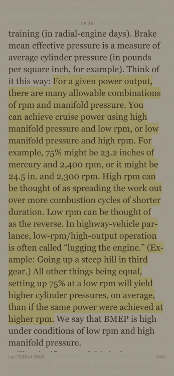
All, feel free to correct my logic. To better understand my engine and its operation, I'd been searching for a solid analogy between a manual transmission car and the Mooney's RPM/MP. While reading Fly the Engine by Kas Thomas, I found the attached highlighted text. I'm posting this here in case it is of interest to anyone else. RPM is to the gearshift as MP is to the accelerator So, trying to climb a steep hill in 3rd gear at either a slow speed or without enough accelerator input is going to cause the car to "lug lug lug"; trying to ascend a thousand feet at (say) 2500 RPM and 18" MP is going to cause the Mooney to "lug lug lug" And, On the interstate, I cruise in 5th Gear at a lighter push on the accelerator; but I could cruise in 4th Gear with a heavier push on the accelerator to get the same speed and that would make the engine hotter On a cross country cruise, I can cruise at 2,700 RPM and 20" MP; but I could also cruise at (about) the same IAS at 2,400 RPM and 23" MP and that would make the engine hotter.
-
@Rlcarter, yes! Very helpful. Thank you.
-
Camshaft, crankshaft, lifters, valves, pushrods, etc. Each time I think about the IO-360 and try to picture how different things work and interact, I keep thinking "Man, I'd love to have a 1/8 scale working model of my Lycoming". I've looked on the internet and found a couple of models on amazon and a couple of cartoons/visualizations but nothing that hits a homrun. Does anyone have any suggestions of websites that have either a model for sale or a (good) graphical representation? If not, I could see myself beginning to take apart the PDF Lycoming parts manual that I have and coloring and labeling it for an exercise in better understanding.
-
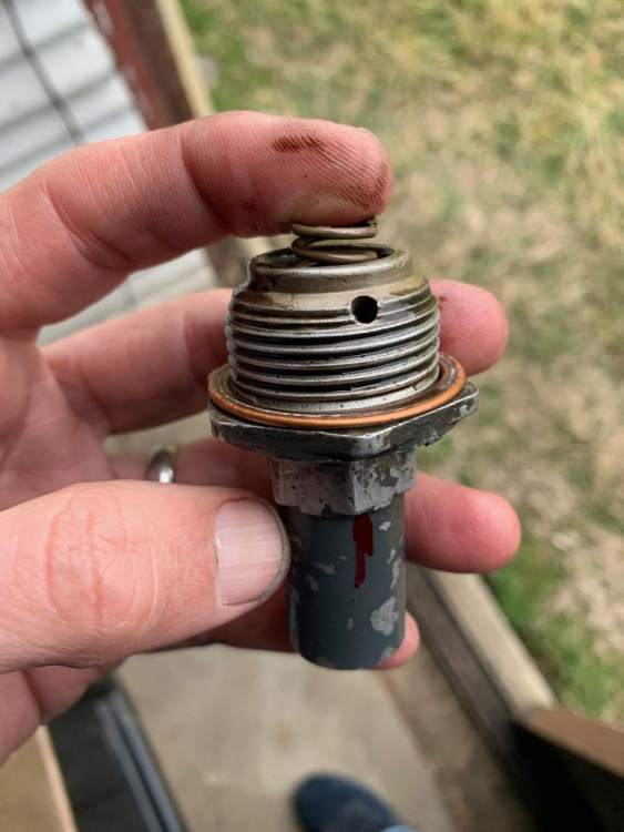
@Ragsf15e, this is related to oil consumption and case pressure. After an annual, I noticed a quicker-to-black oil and greater consumption/use. I'm not sure what type of oil pressure regulator you have, but if you have the ball-bearing-spring-containing, non-adjustable (well, adjustable with washers, not a wrench) type you might look to confirm that the regulator is installed correctly. I may be off base, but it seems that my use/issue went down quite a bit after I saw the this regulator was re-installed with the pass-through holes mis-aligned with the pass through holes in the case.

-
Spontaneous Touch and Go at Newark Airport KEWR
211º replied to 201er's topic in General Mooney Talk
That is awesome. A silver lining in all of this - if there can be one. Sent from my iPad using Tapatalk Pro -
Agreed on check LOP-ness on richest cylinder - IIRC, it is about 20°F LOP and the leanest is about 80°F LOP. I can check my Savvy analysis for that. [Piper cooment] Ha! & Ouch, man! But (for me) there is just something in my brain about flying a four-hour leg that nears closer to five hours and having seven hours in the tank that keeps my pulse and concern at moderate levels. Although I didn't know when I bought it, it seems that I bought the E for its 52 gallons and not its speediness - my mission is most likely in the minority. (It has even occurred to me that my old 150 with long-range 50-gallon tanks and an autopilot might not be too bad a platform - ok, and more wing loading too - I can do without the ragdollness).
-
All good info - especially about the calculation being valid only when LOP due to fuel/air mixture. That makes sense. There is a part of my flying personality that would rather be a little slower and have more time in the air rather than save 15 or 30 minutes and use more fuel. I frequently fly LOP between 5,000 to 9,000 and have a standard setting of 21" and 2350. As I get higher, the %HP increases, but stays below 65%. At this setting I can cruise at about 135mph IAS with a TAS of 149mph and 160mph -- all at 7GPH. With 52 gallon capacity, that is a little over 7 hours in the air - which as noted, fits my flying profile/mission well. After having written that I am going to double check how LOP my leanest cylinder is - there is no roughness, but there is that LOP slight power loss. Maybe I'll end up changing to a standard of 7.5gph or 8.0 gph I appreciate all the input.
-
My Mooney has a JPI 700 which I quite like. It isn't like the 900 or 930 (or 990 - the 2021 update) so it doesn't have percent power. I really like flying LOP and at less than 65% power (to completely eliminate the concern of the red box) In a recent post, I "screen-shotted" the formula for percent power calculation: (14.85 * GPH)/200 = Percent Power = (area of cylinder * GPH)/ HP Engine. If I want to make sure that I'm always below 65% power, is it as simple as: 14.85 * GPH / 200 = 0.65 GPH = 0.65 * 200 / 14.85 = 8.75 GPH So for any setting with manifold pressure and prop where then engine is still running at 8.75 gallons/hr will be less than 65% power. Is that correct?
-
A good reason to not go to CVG.
-
It certainly does. Seeing area ceilings and/or visibility at a glance is also pretty amazing. How soon before something like "two iPads in a cockpit can replace all onboard electronics?" The speed is in MPH.
-
Hi Andy, Yes to ADSB and very many colors. That drop in ground speed was weird - when it occurred I assumed that I’d flown past something, but the only indication of passing something was the decrease in GS. Flying in 2020 is something. ADSB, moving maps, and ATC with a lot of time. While I was contemplating diverting, I asked to divert to CVG (Class Bravo) - Cincinnati approach told me to hang on as I asked for a straight in for runway 9 and they were landing 27. After a minute, Approach came back and vectored me to CVG. (after I turned toward CVG, I thought it was too dark ahead and instead diverted to Cinti West). But to be offered a contra flow landing at a class B! - only in 2020 so far. That E’s 52 gallons and 7 gph LOP flow permits me to take a nominal 3-hr trip and tag on a zig and a zag and still have lots of reserves. Outstanding. I’ll cruise along all day at 135 IAS and 155 TAS all day Instead of dipping into personal fuel minimums.
-
It still makes me talk like an excited kid after I use more and more of the airplane’s ability. Yesterday I flew IFR from Tuscaloosa Alabama to Cincinnati planned via NW Alabama to Bloomington Indiana and a hard right to Cincinnnati. 9,000 above the clouds for most of the way with a descent short of my thunderstorm covered destination. A 90 or so minute wait and I was able to hop over and back into Cincinnati Lunken. 155 TAS at 7 gph LOP gives an easy 6 hours of duration. I still had about 2.7 hours of fuel upon landing. The Mooney is really coming into its own right now.