
Vance Harral
-
Posts
1,477 -
Joined
-
Last visited
-
Days Won
5
Content Type
Profiles
Forums
Blogs
Gallery
Downloads
Media Demo
Events
Everything posted by Vance Harral
-
mats for protecting wing finish during fueling.
Vance Harral replied to Vance Harral's topic in General Mooney Talk
Hard to believe it's been almost 5 years since the beginning of this thread. Our partnership has been using the original silicone mat purchased by Paul the entire time, with no issues. My PIREP below should be taken with a grain of salt, though, as our paint was terrible 5 years ago, and remains terrible today. We're cheap that way. The mat does appear to wrinkle just a little if you spill more than a drop or two of 100LL on it, and I was originally concerned this meant the 100LL was attacking the material and would eventually degrade it. But if you simply wait for the fuel drips to evaporate, the mat goes back to its original shape, and there is no evidence of the material breaking down over the years. I've stopped worrying about it. Note that I have no data on G100UL, as we don't fly anywhere it's available at this time. I do wish the mat was just a little longer on the long side, because with the hole for the fuel port cut as close as is reasonable to one edge, it doesn't quite hang over the leading edge of the wing when placed. This means that while fueling, the fuel hose still rubs directly on the leading edge of the wing, unless you specifically support it with a second hand. But the hose itself is rubber (or some rubber-like compound), and seems unlikely to damage paint, even if you have a nice paint job. The mat definitely protects the wing against accidental dings with the fuel nozzle itself. My favorite thing about the mat is just that it provides a place to set the Shaw cap (with all its scrapey appendages) while fueling. I no longer worry about it sliding off in a breeze or after being bumped, and further scraping up our dime store paint job. Worth it for that alone. As for Paul, I've visited with him recently, and he's well as you might expect. I helped him get a commercial certificate, CFI, and multi rating over the past few years. He recently sold his 252, and is on to other flying adventures, with two taildraggers in his hangar. He's actively using his certificates to teach and ferry airplanes, and I suspect he'll always be involved with the Mooney community, despite (for now) not being a Mooney owner. -
Another Lead (and noise) lawsuit - KAWO Arlington, WA
Vance Harral replied to Igor_U's topic in Miscellaneous Aviation Talk
Yes, and this same problem impacts pig farms, gun ranges, racetracks, and the like. I've been talking with friends about this a lot lately due to similar attacks on airports/operators in our own metro area. The bottom line is that, for better or worse, a large contingent of the population wants to live (and work) just far enough outside downtown to be "country", but not so far that it's more than a short drive to the grocery store, the doctor, etc. The sweet spot where you can do that spreads out every 5-10 years in any town or city that's not actively dying. So until the population collapses and/or literally all the land in the country is developed, airports and things like them are always, eventually going to be at risk from suburbanites. To keep your airport, you've got to convince the population growing around it that it benefits them, at least indirectly. The good news is, that's easier to do that with an airport than it is with a racetrack or gun range. The bad news is, as a group, pilots are pretty terrible at it. Far too much time and energy is wasted on pointless whining that, "The airport was here first". The reason this argument is dumb is that it's easily defeated - the pendulum will swing as soon as some reasonably intelligent person argues, "Yes, we agree the airport was here first, but the majority of our citizens don't care. Just because our community wanted an airport in the 1950s doesn't mean we want one now. Let's talk about the future, not the past, and that future is best for our citizens if the airport is closed." If you want to beat that, you've got to focus on why the airport benefits the town, not on childish prior possession arguments that just enrage the public and provide fodder for politicians. -
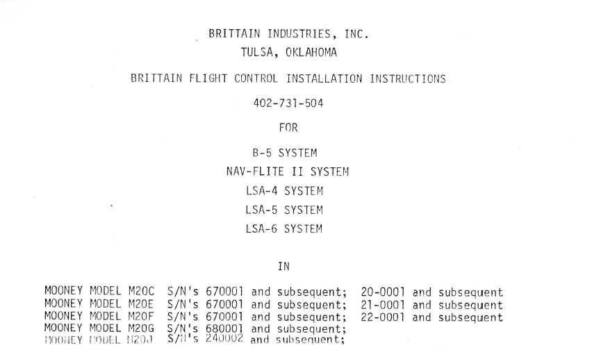
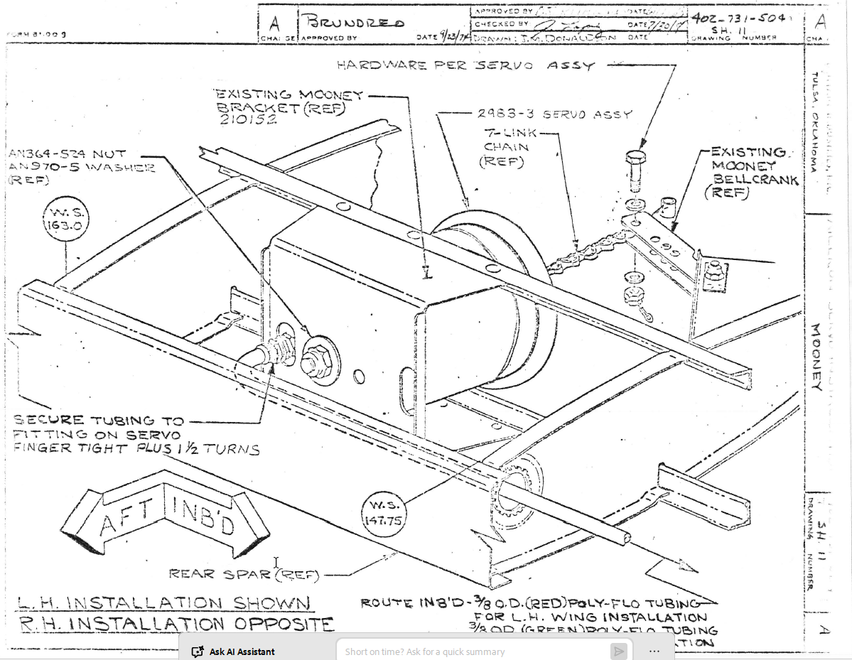
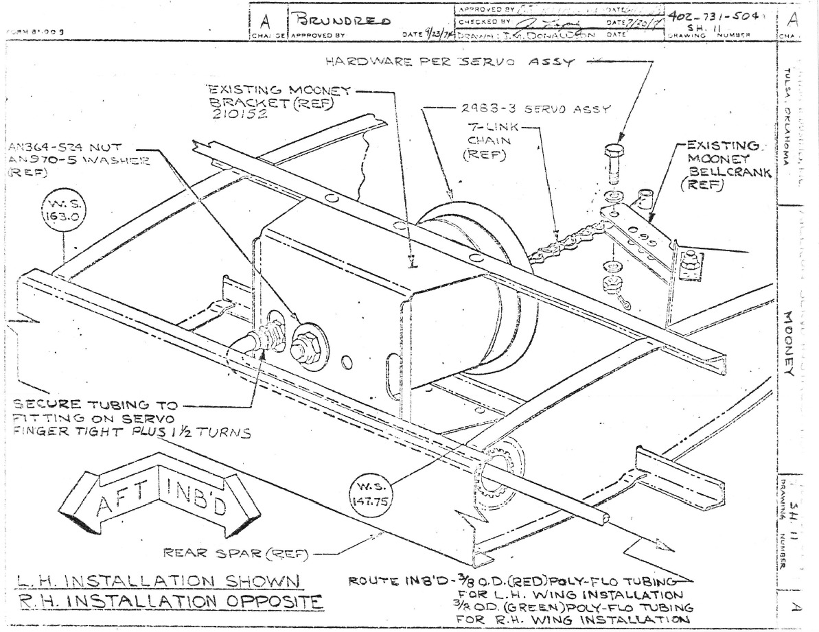
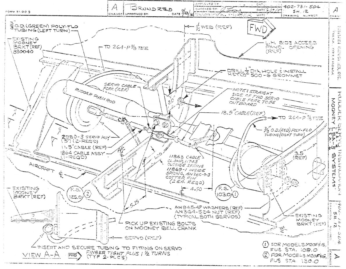
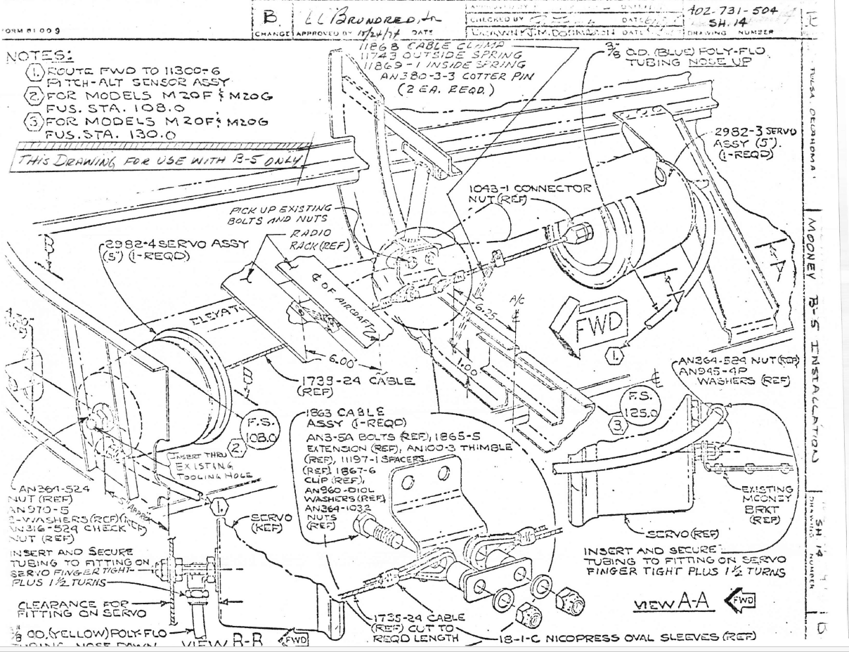
Below are screen shots of the Brittain installation manual for the various autopilot systems. Assuming your airplane is in the listed serial number set, the pages I've pasted have part numbers for the aileron, rudder, and elevator servos, respectively. As you probably know, Brittain is no longer in business, and to my knowledge no one is officially producing parts or overhauling servos. You'll have to look for salvage parts, a new-old-stock "barn find", or mount a repair campaign you and your A&P are legally comfortable with.
-
The M20F Performance Benchmark thread.
Vance Harral replied to Shadrach's topic in Vintage Mooneys (pre-J models)
I live in the Denver Metro area and trek down to the Springs several times a year to go to the Airplane Restaurant for $100 hamburgers. We download and keep our engine monitor data, so I've got plenty of info on this. I went back 3 years and tried to find the absolute hottest day on which I or one of my partners had a recorded flight, correlating temps from https://www.wunderground.com/. The plot below is from July 11, 2023, when the high at KBJC (elevation 5673') was 95 degrees F. It's a long flight, and while we didn't have altitude recording at the time, it's essentially guaranteed by the length of the flight that the climb out was to 3000' AGL or higher. I'm not claiming the flight departed at the hottest point of the day, but it was obviously hot all day long. Hottest CHT in the initial climb peaks at 389F before quickly settling down at level-off. A later climb at higher altitude gets right to 400, again before quickly settling down. I also pulled the raw data from the CSV files over the past two years and sorted it. The highest CHT we've ever recorded on any day under any conditions in those two years is 413F. We've had all-cylinder CHT monitoring since 2006, and in all that time I've never seen anything remotely approaching 450. If you're confident your instrumentation is good and all your baffling is pristine, then the only thing I can think of is you're developing more power than stock, and/or your cylinders run hot (are they chrome perchance?)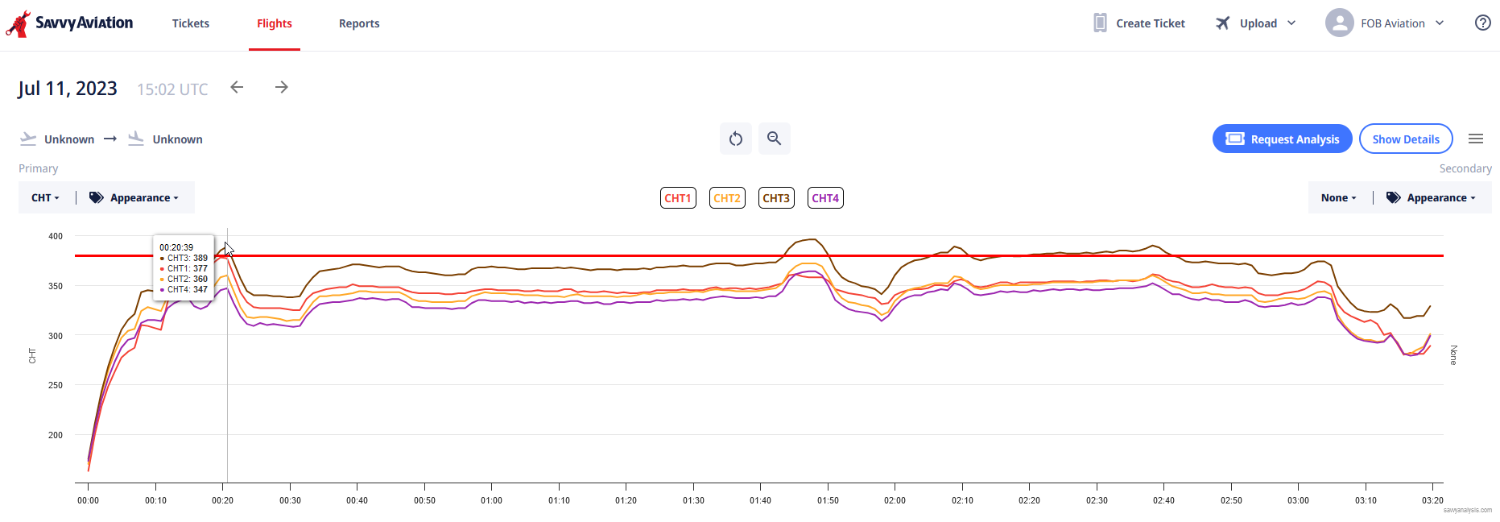
-
The M20F Performance Benchmark thread.
Vance Harral replied to Shadrach's topic in Vintage Mooneys (pre-J models)
I'm sure you're not, but either your instrumentation or your engine or your baffling is amiss somehow. There's no way a stock M20F departing from a Colorado airport should have any cylinder at 450F during a Vy climb, regardless of atmospheric conditions or where the mixture is set. On the very warmest days in summer, our engine might be a few degrees over 400, briefly. I've never seen anything remotely close to the factory redline of 460 in our airplane, or other E/F models I've flown in around here, for 20+ years. -
The M20F Performance Benchmark thread.
Vance Harral replied to Shadrach's topic in Vintage Mooneys (pre-J models)
Nah, not with a correctly functioning engine at high DA. That chart I posted shows the effect of CHT with leaning, it changes by about 10C (roughly 20F) across the "max power" band of mixture settings. A difference of 20 degrees CHT during initial climbout isn't going to destroy a correctly functioning Lycoming, particularly not on departure from a high DA airport in a normally aspirated airplane where you're making considerably less than the full 200hp. If your stock M20F hits 450F CHT during climb out from a 5000' airport - even in the middle of summer - the mixture setting is not the problem. Something is seriously wrong with the engine or the baffling. That doesn't make the target EGT method "wrong", but I think you're over-emphasizing the importance of it on takeoff. It's not a critical number on the takeoff roll or the first 1000' of climb, and it's therefore arguable whether it's worth the distraction of looking at it during a critical phase of flight. It's not so much that it's a huge risk to take a glance, and maybe even tweak the mixture knob based on what you see. But doing so doesn't result in a meaningful difference in performance or safety, so why bother? Ignoring EGT details during this time gives you a few more seconds and neurons to look at things that matter more - like the actual CHTs, which could be the earliest indicators of a problem unrelated to mixture setting, and therefore should be monitored anyway (along with oil pressure and temp). You can glance at the EGT and make a mixture tweak later, at 1000' AGL and about every 1000' thereafter. -
The M20F Performance Benchmark thread.
Vance Harral replied to Shadrach's topic in Vintage Mooneys (pre-J models)
The Koch chart is fine, but the "nerd math" you're asking about is right there in the performance data from the POH I posted. You just have to interpolate. Compute takeoff weight with your particular load (including fuel) and interpolate between the 2300 and 2740 data points, then note the temperature at the selected pressure altitude and interpolate between the temperature points. Or vice-versa, you can start on either axis. At the risk of sounding like a jerk, this is basic private pilot stuff. Regarding mixture setting vs. performance, yes you need to lean appropriately for the DA, and target EGT is a fine way to do so. But note that the curve of power developed vs. mixture setting is pretty flat across its peak. Per the graph below, in the max power rage, differences of 200 degrees EGT only change the power developed by a few percent. So you're not going to see any meaningful difference in takeoff distance and climb rate by getting the mixture setting "perfect" vs. "good enough". This seems to be widely misunderstood, and I fly with lots of pilots who I think spend way too much time fiddling with the mixture during runup at higher DAs in normally aspirated airplanes. Set the mixture "pretty rich" just prior to runup; lean it promptly past peak RPM to roughness; then move it back to about peak plus roughly 1/2" of travel, and you're done. Takes about 5 seconds. If 2% power is the difference between clearing and hitting terrain, that's a judgement problem in deciding to take off in the first place, not a problem with leaning technique.
-
Having instructed in a few airplanes with a single, large glass panel that does "everything", I think there really is an advantage to having the engine instrumentation available on an independent device. The failure rate of the big panels is pretty low, but I'm obligated to simulate "partial panel" on an IPC, and if I choose to do that by simulating a backlight failure of the primary/only display (a very real possibility), it always creeps out the pilot that they no longer have any engine data. The antidote to that is to mange the engine solely by the physical position of the knobs that control it, which most pilots are pretty familiar with. That generally works fine, so I don't think it's some sort of critical error to bundle your engine data solely on a single TV screen with everything else. But it's worth thinking about.
-
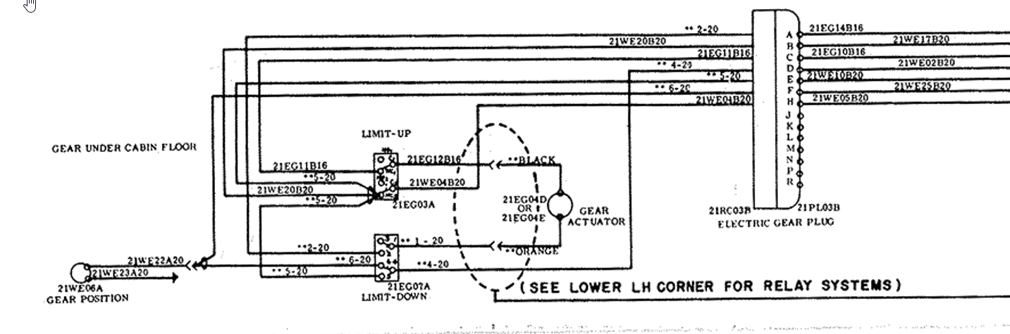
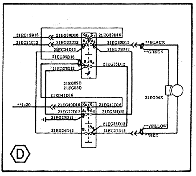
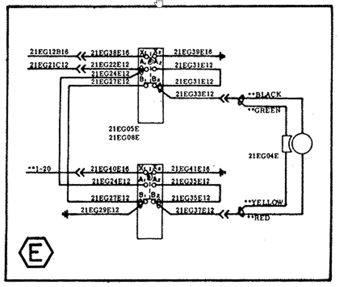
I got curious about this as well and looked in the schematics. The gear selector switch is a DPDT switch, but the schematics for my 1976 M20F show only one pole being used. Moving the switch simply routes a single +12V signal from the landing gear breaker, to one of two output contacts, that - after traversing some of the safety and indicator mechanisms - actuate the "gear motor up" or "gear motor down" relay. It does seem like a single-point failure (broken internal switch guts, loose wire, etc) could command an opposite action from what the pilot selected. It's probably not a very likely failure, and often simple is better. But I'm still slightly surprised at the design.
-
The M20F Performance Benchmark thread.
Vance Harral replied to Shadrach's topic in Vintage Mooneys (pre-J models)
Not sure what version of the M20F POH you're looking at, but the 1975 edition has takeoff and landing data up to 7500' at 70 degrees F, which is about 10,000' DA. Takeoff distance chart is pasted below, landing distance is shorter than takeoff distance for all cases. Real world performance of any stock, airworthy M20F is not meaningfully different from these numbers.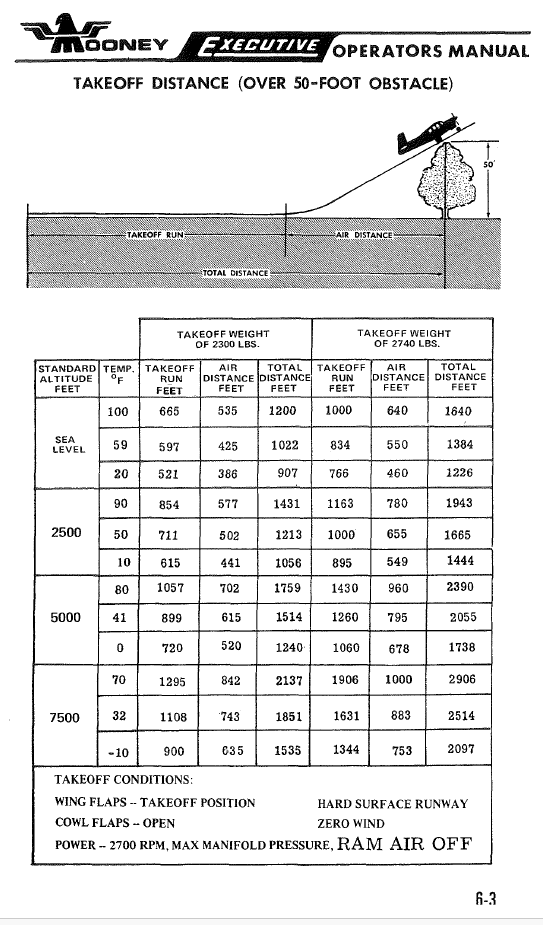
-
This makes sense, but I believe is considered poor practice. I'm sure driving multiple devices from one circuit breaker is done all the time including by major manufacturers. But I once called an avionics supplier about whether it would be OK to gang a voice annunicator that draws less than 100mA with an audio panel that specified a 3A breaker, and you would have thought I was Peter Graves being disavowed by the secretary of whatever. We were out of circuit breaker holes, and wound up powering the voice annunciator through a fuse - as allowed by its installation manual - that tapped off a 12V source right at the bus bars. We put it as close to the bus bar as possible, such that most of the wiring to the voice annunciator was downstream of the fuse.
-
It only has to do with where the fuse/CB breaker is placed, through the mechanical size of those different devices may dictate where they wind up. Otherwise, there is no truth to this idea that one type of circuit interruption device is designed to protect wiring and another to protect the appliance the wire connects to. That's just not correct. Both types of interruption devices can protect both wiring and appliances. Both types of interruption devices provide more safety when placed on/near the bus bar than on/near the appliance being powered. This is due to the nasty failure mode of a power wire which chafes and shorts to ground between the bus bar and the appliance, and winds up carrying more current than it's rated for. This type of failure tends to melt the insulation, dribbling hot, waxy gobs of plastic-like material onto surfaces like clothing and carpet that are prone to catch fire. It's nice to protect the appliance too, but the failure mode of an internal short in the appliance tends to simply burn out a component that's encased in a metal box. It could still hurt you or start a fire, but that's much less likely than an over-current wire. If you can only place one circuit interruption device in the electrical path to an appliance, putting it near the large, robust (cool) bus bar is good because it means most of the wire that might melt is "downstream" of the circuit interruption device. If you instead put the interruption device near the appliance, most of the wire that might short is "upstream" of the interruptor. That's true regardless of whether the poorly-placed interruption device is a breaker or a fuse.
-
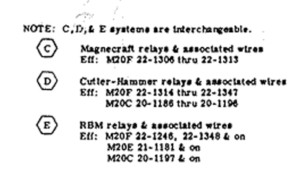
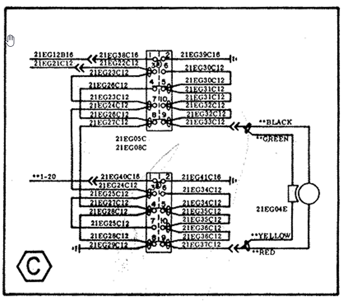
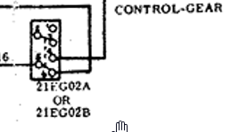
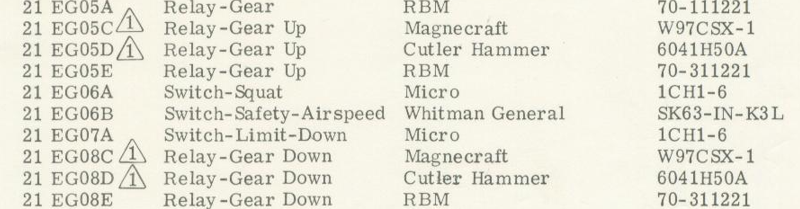
Screen captures of relevant details for M20F s/n 22-1306 and on are pasted below, from a high-res schematic Mooney sent us a long time ago, and the service manual. Part numbers are OEM original from the 1970s. My guess is that some/all of them have been superseded, but you can look up equivalents online. Not sure what you mean by the "switch to drop the gear", as there are a number of switches in the system: the pilot control switch in the cockpit that selects gear up/down, the relays that power the landing gear actuator motor, and the limit switches that cut power to the motor when the gear reaches its final up/down position.


-
Peace and Godspeed, sir. Thanks for being part of our community.
-
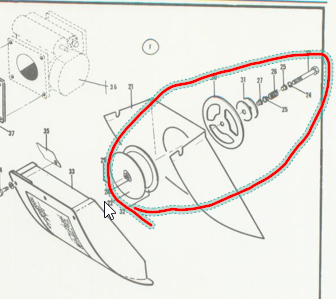
The alternate air mechanism in the E/F is completely independent of the ram air port, and I suspect it's the same in the J. I've circled it in red in the figure below, clipped from the parts manual picture above. It's a round door at the back of the air box, which is ordinarily held closed by spring pressure. If the air pressure inside the air box gets sufficiently lower than the air pressure outside the air box (presumably because the normal intake path through the air filter is blocked), the air pressure difference overcomes the spring pressure and opens the door, drawing air from inside the engine cowl. The mechanism is completely automatic, there is no control in the cockpit for it. The mechanism should be periodically checked (annual, oil changes) for freedom of movement against the spring. Note that if you're in conditions which you suspect might clog the intake system (ice, volcanic ash, whatever), it is critically important to keep the ram air door closed. Opening the ram air door directly exposes the impact tubes of the fuel servo to an unfiltered air stream. If ice or dirt or whatever in that air stream clogs those tubes, the fuel servo stops working as designed, and it's pretty much game over. You can't fix it by closing the ram air door, and the alternate air door won't do you any good. I'd argue that the ram air port is actually the antithesis of "alternate air", since its use is more likely to cause an intake emergency than it is to bail you out of one.
-
It seems to me that the geometry of the components prevents this. If you look at that parts manual diagram above, the lower images are for the carbureted engine. The carburetor airbox is directly inline with the intake path through the air filter. Any mechanism that bypasses the filter would have to take a roundabout route to get to the airbox. I don't think there is room in the cowl for such a mechanism, but even if there was, it would create the same kind of circuitous route the E/F have through the normal intake path, and thereby reduce the benefit of the ram air.
-
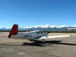
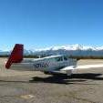
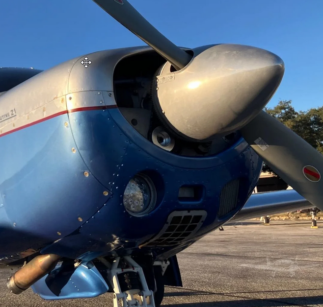
The system is substantially different on the E and F models vs. the J, due to the different cowl. A page from the parts manual and a picture of an M20F are attached below. It's a little hard to follow the parts manual picture, so start with the picture of the actual airplane. In that photo, the ram air port is the rectangular hole directly below the spinner and directly above the air filter. The important thing to understand in the E/F models is that the fuel servo air intake is directly behind the ram air port, but somewhat above the air filter and the air box behind the filter. Therefore, when air enters via the normal intake path, it passes through the air filter, then it must travel an S-shaped path through the air box to get to the fuel servo. If the ram air door is opened, then not only is the air filter bypassed, but the incoming air also has a direct path to the induction system. This is why ram air is somewhat effective in these models. In the J model, the normal induction path is more efficient, hence less benefit from ram air.

-
M20F takeoff and landing performance charts
Vance Harral replied to cstoffel22's topic in Vintage Mooneys (pre-J models)
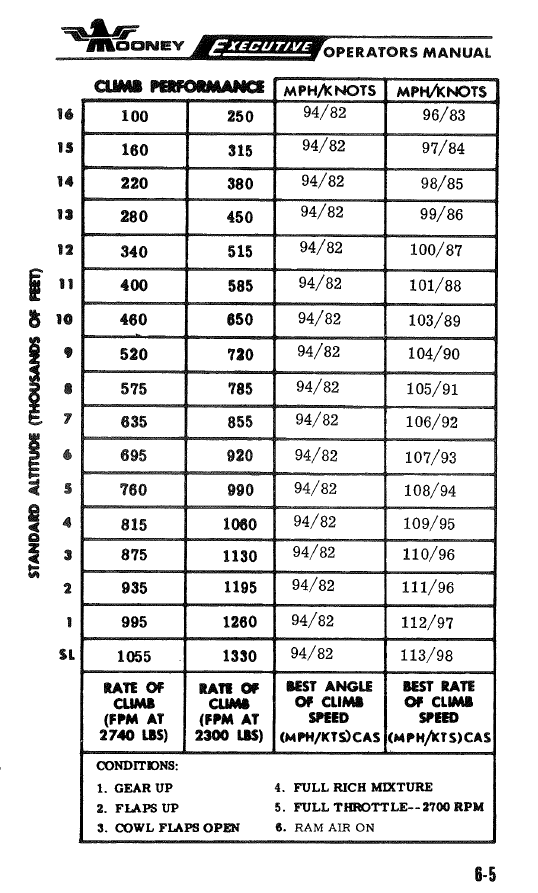
F model takeoff and climb data from the Operator's Manual is pasted below. Note that the takeoff data includes a data point for 7500' at 70 degrees F, which is 10,000' density altitude. Landing distance is shorter than takeoff distance in all cases. We've operated an F model out of the Denver area for 20+ years with no complaints. I've flown it to Leadville, etc. People who say you'll never go back once you've flown a turbo are generally right, but a lot of dual instruction given in K models hasn't made me dislike our F. However, we don't do much hardcore traveling due west over the rocks.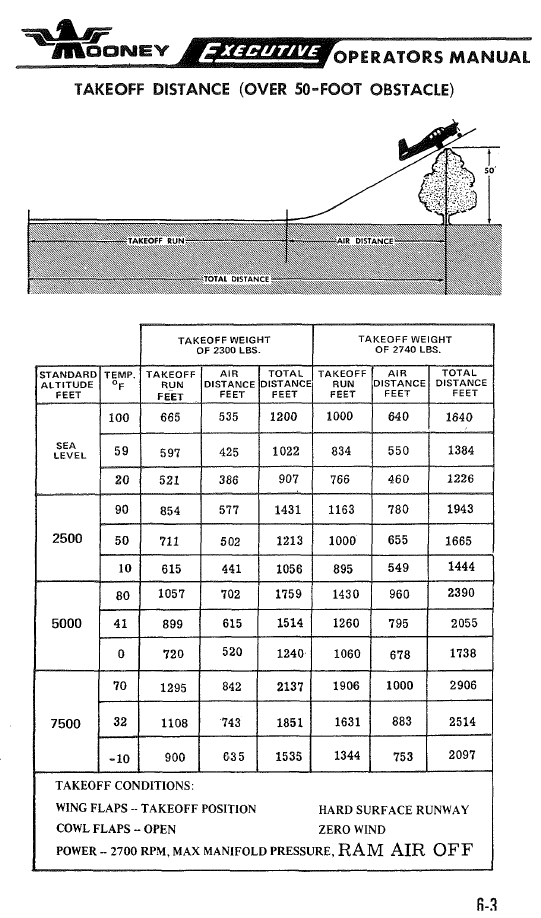
-
Those diagonal braces are factory parts installed on early-year-model M20B/C/D/E/Fs, but not later year models. You can see this in the progression of the parts manuals. Parts manual 202 for the 1961-1964 M20B/C/D/E shows the braces for the B/C/D on p. 106 and for the E on p. 111; and there are no applicability notes, i.e. all airplanes in those year groups have them. Parts manual 203 for the 1965-1967 C/D/E/F shows the braces for the 1965 models on p. 165 and the 1966-67 models on p. 170; but there are per-serial-number applicability notes, which indicate not all airplanes had them. Parts manual 205 for the 1968-1976 models do not show the braces in any diagram and make no mention of them in the parts list. It seems clear that at some point the factory decided the braces were unnecessary and/or caused more problems than they solved, but I do not know why. Our 1976 M20F does not have the braces, but the cowl still has the attach points for them. So every once in a while, some mechanic understandably tries to tell us ours are "missing", and I have to dig out the parts manuals and show them how the factory stopped installing them some time in the 1966-67 time frame. My guess is that Powerflow lists the braces as separate options because they are only supposed to be installed on the earliest year models. If you don't have them, I'm guessing you have a later year model airplane. If you feel they'd be beneficial to you and you want to be "legit", there is probably some legal way to install them using the earlier year models as the basis for approval. But I'll leave that to the actual A&Ps to comment on.
-
Our M20F has ram air, and it's benefit is higher than the M20J due the less optimal induction path with the older cowl. If I'm paying close attention, I can see just under 1" of MP increase by opening the ram air door at varying altitudes. However, the resultant change in cruise speed and/or climb rate is negligible - basically too small to see. The "benefit" is so uninteresting that everyone in the partnership quit fiddling with the ram air control a long time ago. All it seems to do is present an opportunity to forget to close it toward the end of the flight, and thereby ingest unfiltered air into the engine during descent. It also causes us occasional maintenance grief when the rubber seal on the door dries out, or the cable needs to be lubricated, or the warning annunciator circuit gets out of whack. We maintain the system because we want everything on the airplane to work as designed, but if someone offered free parts and labor, we wouldn't hesitate to have it deleted. The benefit with the M20J cowl is even less than on older models, which is why the factory deleted the feature in later years.
-
I'll try to get a data point on this when we have our tanks resealed in February, but it'll just be one data point. We're a good poster child, though, because the fueling policy in our partnership is to fill to the tabs (not full) after each flight, and it's been that way for 20 years. That means we have two decades worth of having the bottom portion of the tank full of fuel almost all the time, and the top inch or two almost always dry. We have several seeps on the bottom of the wings, and I know both tops seep a bit (right worse than left) if you fill the tanks and let the airplane sit an hour or more. Our airplane is hangared, so we don't have the effect of sun heating the top half of the wings with air in the top half of the tanks. But if being immersed in fuel vs. not really makes a difference, I can't think of a much better candidate for a data point than our airplane. If there's a difference and it's visible, we ought to be able to see it.
-
Much as I like our Mooney, this is the sort of thing that really shows how the airframe is sliding into obsolescence. I understand people are just trying to keep their birds viable without breaking the bank, but I cannot imagine jacking up my airplane and/or installing locks in the landing gear suspension to "save the landing gear doughnuts". The risk of the airplane falling off jacks is pretty small if you're careful, but it's a catastrophic event if it happens, and the likelihood of it happening goes way up if you're doing it literally every time you put the airplane away. Lots of airframe models remain viable after being orphaned by the manufacturer (and let's not kid ourselves, that's the state of Mooney). But beyond a certain point, it becomes ridiculous. Imagine the reaction of a potential new owner, or the peals of laughter from the local hangar crowd. "Yeah, a Mooney is a pretty nice airplane, but the design of the landing gear is so dumb that you've gotta put it up on jacks when you're not flying it".
-
That's probably the correct range for airplanes with larger tanks: later models from the factory and/or those with Monroy long-range STC. Yep, that was our strategy for two decades, and I don't regret it. The cost of the patches worked out to less than $5/hour for us, which is arguably in the noise of operating cost. But nothing lasts forever. You have to guess at how much longer you think you'll own the airplane, estimate inflation, time value of money, etc. I kinda wish we'd ponied up for that "too expensive" paint job in 2005, when we could have had a pretty good one for under $10K. That same paint job would be over $20K now. As for the G100UL thing, I guess it remains to be seen the degree to which this is actually a function of tank sealant health. We're of course hoping a fresh seal job buys us some insulation against the problem, if we use G100UL in the future. But there isn't enough at-scale-in-the-market data to be sure, and for better or worse we're not going to wait on it. If G100UL is a major cosmetic problem for people like us who ride the tail of the sealant curve, I can only imagine how irritated people with young sealant (and often nice paint jobs) will be if G100UL turns out to be - even just cosmetically - incompatible with wet wings.
-
No criticism of your strategy, we also paid $1-2K for patches every few years, for the last 20 years, and it served us well. That said, your estimate for a reseal is pessimistic by more than $5K. After about 50 years of original sealant plus patches, we decided to bite the bullet, and have an appointment with Don Maxwell at the beginning of February for a full strip and reseal on our M20F with 64 gallon tanks (roughly the same vintage as yours, I recall). The contracted price is $9600 for both sides. 7 year warranty, for what that's worth. The $9600 quote doesn't include travel costs. Round trip from Denver to Longview in the Mooney will put about 8 hours on the airplane, but it's hard to say whether that should be included in the accounting or not, as we like to fly and would likely have gone somewhere else instead. Short-notice round trip airfare from Longview home, then back for pickup, adds about $750 (anyone traveling from northeast Texas to Denver around the end of January, and/or in the other direction around end of February?) I don't know whether to feel better or worse that we scheduled this reseal right before the recent news about G100UL and Mooney tanks. No G100UL in Colorado for now, but it's obviously a strategic concern. We're unconvinced bladders are a better bet on that front, and slightly prefer wet wings for other reasons as well. The other alternative was to do nothing, but we had reached a point where we were concerned the airplane might spring a significant leak that would make it difficult to deliver it even to a shop that would patch it. You also just get tired of looking at the ugly blue/brown stains after a while. Even when it's not a safety of flight issue, it starts to feel like you're neglecting the airplane and creating a major sticking point for sale somewhere down the road.
-
Couple of caveats about this. First, while the Duke's and ITT actuators are largely the same, one difference with the later ITT actuators is that they lack a Zerk fitting to add grease in situ. Thus, you can't "give it a few pumps of grease till it comes out the screw hole, while in the plane", at least not the way those with the Duke's actuators can. You can remove two of the screws and pump grease into one hole with a cone tip until it comes out the other. But I've never had much luck with this, as access is awkward and it's difficult to get the cont tip to actually seal well enough against screw hole #1 to pump through to screw hole #2. I've gotten to the point where I simply don't try to lube the gear cavity without removing the actuator from the airplane and disassembling it. I've done this enough times now that it's not a particularly big hassle. The other caveat is that if you use this technique of pushing grease through one hole (zerk or screw) until it comes out another, you've got to be sure to take enough grease out of the last hole before you reinstall the bolt, to ensure the bolt doesn't hydro-lock against the grease in the cavity, and strip the threads of the actuator. You can guess how I know this.


