

Jake@BevanAviation
-
Posts
229 -
Joined
-
Last visited
Content Type
Profiles
Forums
Blogs
Gallery
Downloads
Events
Store
Everything posted by Jake@BevanAviation
-
 Wrong IM, you need the one for the KAP/KFC 200 system.
 -
New G-5 HSI and Autopilot Interface Problems
Jake@BevanAviation replied to bucko's topic in General Mooney Talk
Start with checking the S-Tec unit strapping for the compass system, it needs to be strapped for a KCS-55A (KI-525A). If this is not done the system will not work correctly. After that check servo rigging and start-up voltage. Ideally the start-up voltage needs to be under 2VDC, the lower the better. Also, depending on what was removed (DG/HSI) you might want to double check that the unit is still getting the L/R radio error. The GAD29B only provides the Heading/Course error. L/R radio deviation (analog) has to come from the primary navigator to the S-Tec unit. -
MET (manual electric trim) has separate circuitry vs autotrim. MET can be functional but have a issue with autotrim functions and still be related to the trim servo. Easiest way to see where the issue is by unplugging the trim servo and monitor the drive lines from the computer for autotrim functions with a DC volt meter. Do a autotrim test (can be push/pull or use the UP/DN switch in the KC290) and monitor the DC volt meter. Ideally without the micro-switches being closed in the pitch servo the computer should generate no drive. When a micro-switch in the pitch servo is closed and remains closed there is a 3-5 second delay before the computer will issue a autotrim command. The autotrim command from the computer will stop when the micro-switch is opened. If the computer checks out with the closing of the pitch servo micro-switches and autotrim drive being issued, the issue is with the trim servo. In normal operation if the computer detects a trim runaway condition (trim feedback) without a autotrim drive command being issued it will issue a trim fail warning. Copies of the IM can be found in the download section for interconnect reference.
-
It will engage but it will not be happy and will have a constant trim warning.
-
KFC 150 Strange behavior altitude hold / preselect.
Jake@BevanAviation replied to redbaron1982's topic in General Mooney Talk
The logic in the computer for the mode buttons is pretty simple, 5VDC pull up resistors tied to the button switch that pulls the line low when the button is depressed. After that it runs into 8bit shift register IC and then the microprocessor. If I had to guess maybe a issue with the shift register or possibly the microprocessor. I would try and isolate out the KAS297B and see if the issue stops. Also, KC192 computers manufacture between 1991 and 1998 have capacitor leakage problems. There should be a red or black stamp on the side/back of the unit that has a 4 digit code for example 1393 would be the 13th week of 1993. I would try to see if your unit falls in the manufacture range. When the capacitors leak they can cause some really weird issues with the flight computer. -
KAP 150 Autopilot Issue
Jake@BevanAviation replied to togapilot's topic in Avionics/Panel Discussion
Without the compass valid I believe it will pass pft, but when trying to select a lateral mode it will not allow it. With the heading flag in view it should not allow any lateral modes. If the system is engaged in a lateral control mode and you loose the compass valid the system should disengage. It will allow you to engage with FD and a vertical mode but you will not be able to select a lateral mode. -
Electric trim intermittent failures
Jake@BevanAviation replied to ReconMax's topic in Modern Mooney Discussion
Record the state of the failure, any flashing lights, what part of the system is INOP. There is a trim fail light in the bezel of the flight computer. During PFT test the trim light will flash 4 times. If the regulated trim voltage is missing you will not get any flashes during PFT and it will have constant flash at the end of the test. KC192 manufactured from 1991-1998 have issues with capacitor leakage and can cause some weird intermittent issues. They tend to fail when they are thermal cycled, they will work when cold but tend to fail when the unit has been running. m20 j kfc 150 interconnect.pdf -
KAP 150 Autopilot Issue
Jake@BevanAviation replied to togapilot's topic in Avionics/Panel Discussion
If the system will not let you select a lateral mode of operation my guess is you are loosing the compass valid input to the flight computer. -
Electric trim intermittent failures
Jake@BevanAviation replied to ReconMax's topic in Modern Mooney Discussion
KFC 150 system has a trim monitor circuit that looks at the regulated trim voltage. If for some reason the regulated trim voltage is dropping out or the trim servo is loosing power/ground the regulator will stop functioning. When this happens the system will not pass pft and have a constant flashing trim light. If you could get a video of the failure that might help a little. Weak return springs in the MET (manual electric trim) switch have been known to cause intermittent issues especially the left side of the split rocker. -
Nope, you can have a failed transducer board and it will pass PFT.
-
If the issue is related to alt hold functions only it might be an issue with the transducer board. This board only does alt hold functions. If you can set a climb and descent rate and the aircraft auto-trims properly with power changes I would guess the servos are probably ok. A good test of the auto trim function might not be a bad idea as well. Typically when the transducer boards fail you get a hard up or a hard down when selecting alt hold and they will not level out.
-
KAP 150 "HDG" Light Burned Out
Jake@BevanAviation replied to MisfitSELF's topic in Avionics/Panel Discussion
To remove the bezel the unit will have to be removed from the rack and the static line disconnected. There are 4 screws on the side of the unit that hold the bezel to the frame and 4 screws on the inside of the unit that hold the bezel to the motherboard. To remove the 4 screws on the inside you have to take the top cover off and take the screws out of the top motherboard. -
KAP 150 "HDG" Light Burned Out
Jake@BevanAviation replied to MisfitSELF's topic in Avionics/Panel Discussion
@MisfitSELF You could try and swap the lamp with a different one and see if the problem follows the lamp. If the lamp fails to illuminate during PFT the lamp has failed. If the problem doesn't follow the lamp it could be a logic problem with the flight computer. -
Century 2B - S turns while tracking
Jake@BevanAviation replied to joepilotmooney's topic in Modern Mooney Discussion
Servo start-up voltage is super critical on these servos. Ideally it needs to be under 2VDC (the lower the better). Typically, after servicing a unit the start-up is around 800mvDC. If the start-up voltage is too high, the servo is slow to respond causing issues with oscillations or poor tracking. Checking servo start-up voltage is probably a good idea if the servo has not been looked at for some time. -
@rocketman if the top and bottom adapter modules match the specific modules needed for the aircraft in theory you should not need to swap. However, it would be nice to know if when the unit was bench check was the aircraft modules installed or were the test modules used? The only servo the system cares about for PFT functions is the trim servo. Specifically, the regulated trim voltage and the feedback from the drive motor. It might be worth it to swap the modules as you have no known history of the ones in the as removed unit. If the modules in the as removed unit had broken pins it could explain why the unit will not PFT. If the shop used the "test modules" there is a good chance the unit worked just fine.
-
@Fly Boomer Yep, the flight computer needs to have the top and bottom modules installed to start a PFT test. Checked this on the bench with a test KC191 (KAP-150). Without the modules the unit will not PFT. Only the trim annunciation stays lit.
-
Did you transfer the top and bottom board modules from your original unit to the new as removed unit?
-
@PT20J you are 100% correct. The autopilot system uses multiple boxes to process the incoming information and send the commands for correction out the the servos to control the aircraft. The flight computer (KC192) takes in information from the AI, HSI and primary navigator. Sums all this information together and produces a correction drive for the servos. The FD is a function of the autopilot flight computer. It gives a visual indication on the AI of what the system is trying to do based on the information it is given. The FD bars should always mimic the servo drive. If you ever have separation in the FD bars vs what the aircraft is doing with the autopilot engaged, you have a problem within the system.
-
FD drive always comes from the flight computer (legacy systems).
-
Aspen/KFC150 AP AHRS Fail Light
Jake@BevanAviation replied to Scottknoll's topic in Modern Mooney Discussion
@PhateX1337My initial thought is some communication problem with the EA100, see print below. Ideally if the PFD has fully booted, then you turn on the radio master, the EA100 should communicate with the EFD, if the information is correct the ACU should tell the EA100 to extinguish the A/P AHRS fail annunciation. It's not uncommon to hear about EA100 failures. When they do fail you will have the A/P AHRS fail annunciation constantly and the A/P will not be able to engage. Aspen requires that their Ethernet cable be used for communication between the EA100 and the EFD and terminated correctly, if the required cable is not terminated correctly it can cause interference issues with the EA100 per the IM.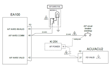

-
King KFC200, Garmin G5/GAD
Jake@BevanAviation replied to Gongse's topic in Avionics/Panel Discussion
You have to keep the the KI256 for the attitude information, The G5 AI can not provide attitude information for the system but a GI275 can. The G5 and GAD29B will only provide GPSS, heading and course errors to the flight computer. Lateral and vertical deflection has to come from the primary navigator to the flight computer. Also, don't forget the compass valid (ground) to the flight computer. Without the compass valid you will not be able to select any lateral modes with the flight computer engaged. -
Century IIb not following new IFD 440 in NAV mode
Jake@BevanAviation replied to Bartman's topic in Avionics/Panel Discussion
@MoonFlyer68 If you want to give me a call on Monday we can discuss the details on the issue in the aircraft. Ideally there should be no change in the signal generation with a Garmin unit vs Avidyne. They should both follow the standard deviation signal of around 30mvDC per dot. -
Unfortunately, with the current state of Century Flight Systems getting a Century 41 fully operational and reliable might be a big issue. A lot of the parts are no longer available for this system. Century is no longer doing repairs at the factory to my knowledge and has very limited support. Due to this reason I stopped working on the C41 years ago and would only send the system back to the factory for repair. The last system I sent in years ago came back with a 9K estimate for repair. My recommendation would be to replace it when you can for better reliability and support with a newer modern AP system like Garmin. There still might be some shops out there trying to do bench repairs but parts will be the biggest limitation. Altitude transducer problems were not uncommon for this system.
-
G5 HSI / Century 41 / gtn750 RNAV Approach
Jake@BevanAviation replied to haymak3r's topic in Avionics/Panel Discussion
The G5 via the GAD29B can only provide heading or course errors to legacy autopilot systems. The vertical and lateral deflection (analog) must come from the primary navigator to the flight computer. When trying to couple the ILS or GPS approach the A/P system must be in approach mode with full up deflection on the vertical. The system has an anticipation circuit for the G/S capture that will monitor the closure rate of the vertical deviation signal and anticipate the capture. You can use GPSS to navigate to the fix, but you must turn it off and activate approach mode if you want to capture the vertical. -
If in just attitude mode, with heading not selected and the system has the roll oscillation, with a level ADI. My first thought is tach gen feedback from the roll servo. If the compass system has not finished slaving the card will oscillate back and forth until it is slaved. During the slaving operation the compass valid output will be invalid, this should keep the AP from selecting heading mode. However, if someone has wired around the compass valid input to the flight computer you could select heading mode with the compass system still trying to slave and you would have a oscillation in flight. Once the system slaves the problem would go away. Something to look for during the oscillation would be is the heading flag on the HSI still in view? Best thing to try is see how the ap system does wings level without the compass system being used, so no heading mode just FD and AP on. If it still oscillates the compass system is not your problem.

