

Shadrach
-
Posts
12,165 -
Joined
-
Last visited
-
Days Won
170
Content Type
Profiles
Forums
Blogs
Gallery
Downloads
Events
Store
Everything posted by Shadrach
-
I used to have access to a set of ratcheting jacks. 3 legs with a large threaded jack shaft and a ratcheting threaded collar. They were dirt simple, easy to use and almost fail and fool proof. They were stamped Made in Poland. The owner foolishly gave them away when he sold his airplane. He was in “I’m done with aviation mode”…2 months later he bought a PA28-180 now he’s in “why did I give those jacks away” mode. If anyone is familiar with jacks as I’ve described them and knows what they are or how to source them, I would appreciate any info.
-
book climb numbers for a J vs an XP at MGW favor the J by almost 200fpm. If an XP feels like a stronger climber on the same day it’s likely perception rather than reality unless something is wrong.
-
I mean yes, but an image of a purpose built jack stand sticking through the wing of a large part 129 turbine aircraft doesn’t really point to the jack stand as the problem. The message is more, be very careful with aircraft on jacks as things can go wrong for anyone not taking special care
-
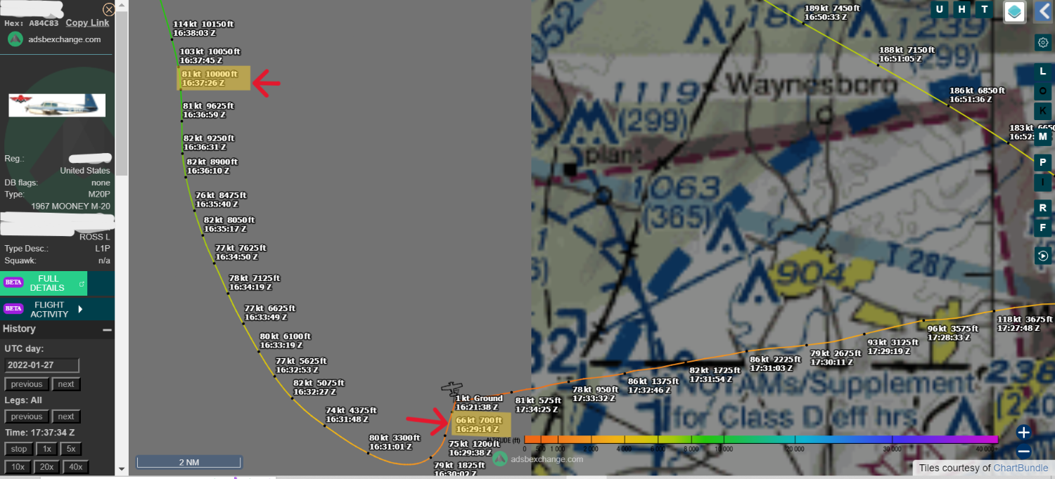
If a 180hp C172 will out climb your airplane than something odd is going on with the loading comparison, or there is a problem with your plane. I have lots of time in 172s I don’t think any of them will out climb my plane to 10k including the XP. In response to your claims, I posted the closest thing I could to verifiable, 3rd party data showing a climb from 700’ to 10000’ in 8mins 12 seconds for an average of >1100fps. Crickets. Maybe it’s just that the Mooneys you’ve flown are tubby in the weight department. Perhaps there are other factors. But your assertion that they don’t climb well is not founded in actual numbers. Pound for pound they are top of class climbers and more useable above 8k than most other 200hp birds. I did my high performance checkout in a P-ponk C180K. It did not feel high performance at all coming from the little 200hp Mooney I flew right before the checkout.
-

Mooney for a tall guy in NJ (Tri-State?) area
Shadrach replied to Ive's topic in General Mooney Talk
A Cardinal would be more dignified. Another way to get him in the Mooney would be to lift him (cradle position) onto the wing walk from the front and then place his legs in the footwell followed by the torso. Not ideal but doable. -
Extra 200 and Aviat Pitts S1 come to mind. The Arrow, Cardinal, Cutlass, Comanche and Sierra all fall short.
-
Mooney for a tall guy in NJ (Tri-State?) area
Shadrach replied to Ive's topic in General Mooney Talk
Good idea. I think the Mooney step (regardless of model) presents a pretty generous and stable footprint but a large platform allows for both feet to have a purchase before transitioning to the wing. -
What model Mooney? Both tanks or just one? An 1/8th of a gallon is a lot of water, for 64gal tanks and up, that should not be enough to displace the unusable fuel and enter the fuel lines. Perhaps there is something else causing the problem?
-
Mooney for a tall guy in NJ (Tri-State?) area
Shadrach replied to Ive's topic in General Mooney Talk
There is no easy way. We had a paraplegic pilot on the field that owned an Arrow. He climbed up on the front of wing using his arms and would then fold his chair and pull it up and into the plane. He may have had a special handle installed externally just ahead of the door hinge. He had special hand operated rudder controls installed. As for your 97 father, the only answer is very carefully. If he can walk, its best to have a helper on the wing in front of him and a helper at the trailing edge behind him to ensure that the transition from the ground, to the step, to the wing walk goes as it should. So many folks are reluctant to use the handle just above the windshield on the passenger side. I ask that people secure a handhold to to the handle, then step in and sit down. I advise the reverse order to get out, but some just roll out onto the wing on all fours without listening. -
Mooney for a tall guy in NJ (Tri-State?) area
Shadrach replied to Ive's topic in General Mooney Talk
It’s all about inseam. I’m not quite 6’ and have a 31” inseam. That puts me in the first seat notch back from full forward. It also gives my rear passenger more leg room than a lot of commercial flights. I think the seat will accommodate inseams in excess of 37”. It’s not a graceful plane for almost any sized adult as far as ingress and egress go, but the door is large enough for and located so that any one that can get in can scramble out. It’s not an easy plane for the infirm or mobility challenged elderly, but few are. -
Andrei, I did the job under supervision. I’m not sure it’s worth it. I’m sure many pros are faster than me but I would guess 4-5hrs min. The service manual is pretty light on details in this area. I put the engine on a hoist and removed the two bolts that hold the upper motor mount to the firewall. After disconnecting the necessary hoses and wiring, I tilted the engine forward to access the governor. With the engine tilted forward there is adequate but not a surplus of room. The pain was getting the mount back against the firewall. The location of my engine hoist point caused the nose wheel to lift before the mount would mate flush against the firewall. I had to use a ratchet strap in combination with the hoist to line everything up. I am sure that more experienced mechanics know some short cuts. I’m just glad I got the governor right on the first try. I suspect mine was on the low side because the original installing shop said “good enough” rather than go to the trouble to adjust it further.
-
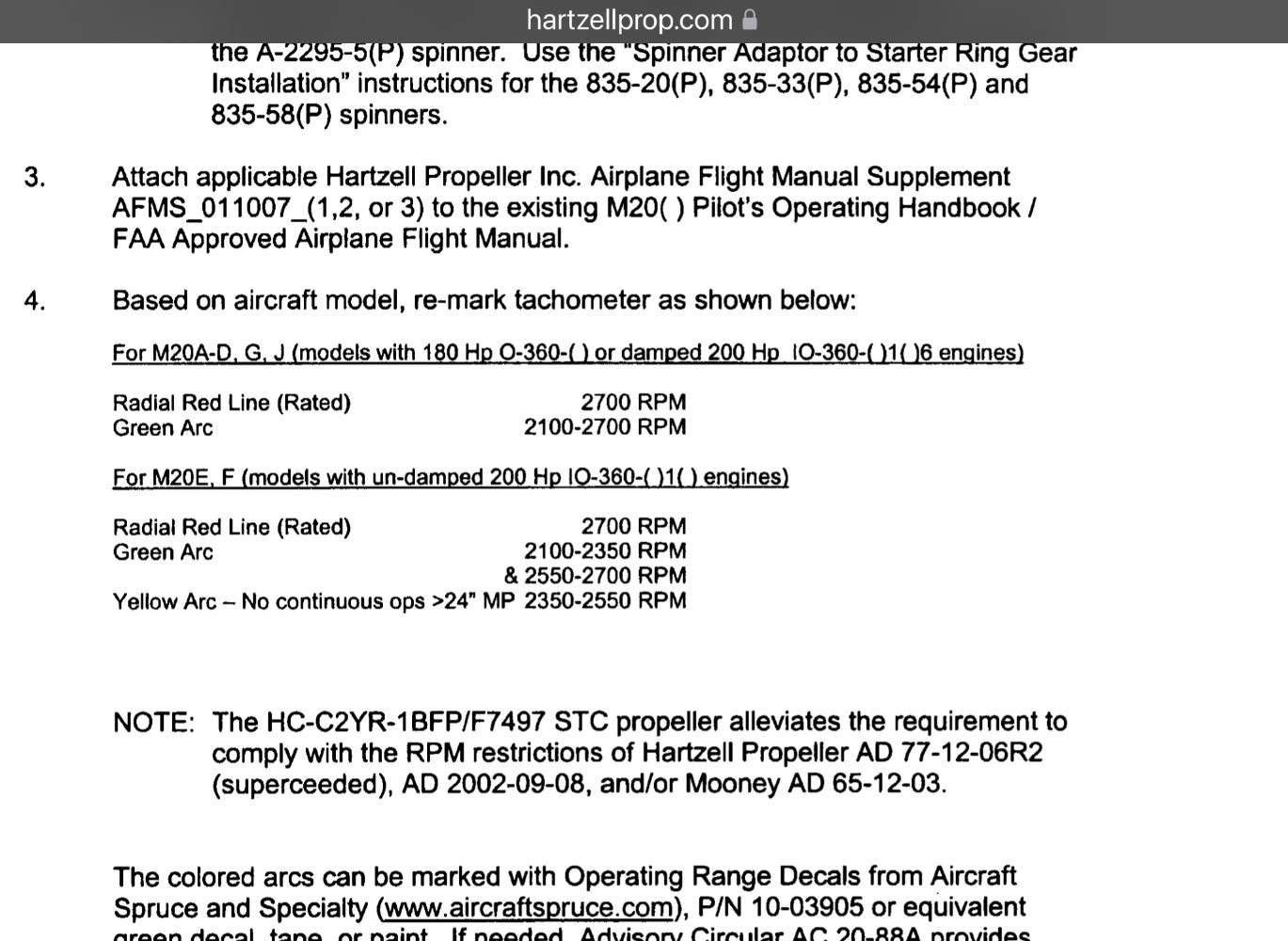
I screwed up. That is the 3 bade. 2 blade is here. https://hartzellprop.com/wp-content/uploads/SA02414CH-D_INST.pdf
-
Edit. STC corrected. Link to STC. https://hartzellprop.com/wp-content/uploads/SA02414CH-D_INST.pdf
-
What prop do you have?
-
Just sorry he was in a Mooney
Shadrach replied to Brandt's topic in Mooney Safety & Accident Discussion
Absolutely. If he’d have made it out and sobered up en route It’s unlikely he’d have been caught. I don’t think this was his first time flying impaired. Maybe just his first time flying drunk out of a controlled airport. -
What aircraft are you comparing them to? What other certified, N/A 200hp, 4 plc SEL can do better than the time to climb shown below? Yes, I was trying to do a max performance climb. Yes, it was a cold day (32° @ 29.42 according to Wunderground historic weather) and...Yes, it was just me and around half tanks. However, unless my math is off, the numbers below show 8 mins 12 secs from rotation (700') to 10,000' (9300' ascent) for an average ROC of 1134 FPM. Perhaps ADSB exchange is giving unreliable data?
-
It’s very odd, hypoxia. I have seen it take out very fit people in the high country. I’ve never done a chamber ride but have done intense hiking at DA’s well above 14k. I don’t feel mentally impaired doing strenuous exercise at altitude but I certainly sound different in videos that I have taken narrating the surrounding landscape.
-
Makes sense. Minimal amount of air available but mixture changes are happening at the same scale as the are at low altitude.
-
I’m certain that static or take off or climb, my engine was over >2600rpm. My governor was at the stop. I had to rotate the whole assembly in its housing to get RPM to max. It would be nice to have Clarence’s input as this is not a super common procedure in the field as far as I can tell. My IA had never done it.
-
That’s kind of a silly statement. If that’s the “apples to apples” comparison you’re making then there is no benefit to having a lighter weight Aircraft. I don’t think I have ever had my airplane to MGW. I have been within 100lbs a handful of times. At max fuel (only happens when tankering fuel) my wife and me with weekend bags are >300lbs under gross. Reality is that most of my flying is conducted at 300-600lbs under gross. And it’s not like I don’t have any fuel on board. Me with half tanks put the airplane at 2087lbs or ~650lbs under gross. There are some Js out there that weigh nearly that much empty. It’s definitely a consideration.
-
Well wherever we end up is hopefully close enough. I do not want to get back into that governor. I will report back after post mx shake out.
-
Must be a Florida DA thing. Could be a weight thing too. At solo weight this time of year I see initial rates of 1300-1500ft and hold greater than 1000 through 5K. Me +4hrs of fuel puts my bird at 2150lbs. A while back I did a time to climb from takeoff to a pressure alt of 10,500 and I believe I averaged over 800FPM from breaking ground to altitude intercept. I'll have to find the date so I can check the ADSB data.
-
I don't know yet. My Mechanic has not done the final inspection yet. Our schedules keep conflicting for the final inspection and many of those "while I'm in here" situations. A lot of of little detailed jobs and messy jobs.
-
As others have said, climb full throttle, max RPM, there is no benefit to throttling an IO360 in the climb. At wide open throttle, internal cylinder pressure and therefor CHTs will likely be lower at 2700 than they will at 2500. Don't lean just for the sake of leaning. At max power, you want to be a minimum of 250° ROP (peak EGT "readings" for an IO360 are typically 1450°-1525°). That means EGTs should be in the low to mid 1200s at the highest (mid to high 1100s are fine too). Verify that takeoff EGTs are in range (I do this on every flight) and then use the EGT on the richest cylinder (likely but not necessarily #3 for your engine) to maintain take off EGT (+/- 50°).
-
Interesting discussion for me as I just reclocked my PCU5000 per the installation guide. I was maxing at 2640rpm in climb as measured by an optical tach. After reclocking (that's a whole "nother" thread) We are now at a constant 2700 but it does push to 2730 for a split second if you advance too aggressively. So it seems that the governor is what is holding it at 2700 rather than the pitch stop. I am sure that the pitch stop is close. I am glad I got it right the first time. The Lycoming governor location combined with the proximity of the accessory to the firewall is terrible in terms of accessibility.
