

Vance Harral
-
Posts
1,482 -
Joined
-
Last visited
-
Days Won
5
Content Type
Profiles
Forums
Blogs
Gallery
Downloads
Media Demo
Events
Everything posted by Vance Harral
-

Multiple OAT's and GPS antennas
Vance Harral replied to TuomoMooneyFlying's topic in Avionics/Panel Discussion
The G5 has no A429 inputs. If you have a GAD29B - which many installations do - you can send A429 data to that, and it will convert to CANBUS and pass it along to the G5. This works in the other direction too - e.g. our GTN gets air data from the G5 on A429 inputs - but this only works because the GAD29B is there to bridge the two busses. I don't mean to be a pedant about it - it's not really incorrect to say a G5 can get temp data "via A429". But for people trying to decide what they want and how much it's going to cost, it's important to understand the architecture. A G5 has an RS-232 interface for GPS position data, and CANBUS for everything else. Accordingly, any air data device that doesn't natively speak CANBUS will need a GAD bridge to communicate with the G5. -
Multiple OAT's and GPS antennas
Vance Harral replied to TuomoMooneyFlying's topic in Avionics/Panel Discussion
The G5 is primarily a CANBUS device, so any temperature data it receives has to be transmitted over that network. The main reason it can't get temperature data from existing probes is that those probes and/or the devices they connect to don't have a CANBUS interface to talk to the G5. The probes themselves aren't CANBUS devices either, but Garmin provides the GAD13 device to bridge analog temperature probe data to the CANBUS network. It's technically possible you could gang an existing temperature probe in parallel to a GAD13 and whatever it normally talks to; but I don't know the impedance implications of that, and you're into experimental territory anyway. As others have pointed out, you probably don't need an additional GPS antenna to install a G5 or two. They have a coax connector for an antenna, but they can also be set up to receive location data from a WAAS navigator over an RS-232 connection (which is independent from the CANBUS interface), and the latter is how most are installed. The other curious trick is that in many installations, the GPS receiver in a G5 will acquire satellites even with no antenna attached to the coax connection on the back. The installation manual doesn't allow exploiting this in a certified installation, but it's interesting. We have the temperature probe in our G5 installation, so we get OAT, density altitude, TAS, winds aloft, etc. It's kind of a fun gimmick, but I wouldn't agonize over adding the OAT probe if you don't have one. What I've found in practice is that the TAS and winds aloft are only accurate during a long, steady state experiment. It tends to be inaccurate when maneuvering (my guess is it's displaying a weighted average of samples over time). So it's frankly not that much help for tactical things like picking a wind correction angle in a holding pattern or approach leg. You can do just as well with GPS ground speed and ground track. Seeing density altitude while taxiing out is kind of cute. But pilots smart enough to understand the implications of DA already know the DA from math and/or the ubiquitous AWOS warnings. The G5 doesn't display the DA in flight (at least not by default), so it's not going to help you understand the likelihood of getting over a tall rock. I don't regret the extra time and effort of installing the OAT probe, but with a few hours under our belts flying with it, it just turns out that like many of these things, it doesn't really make an operational difference. -
Instrument Study book recommendation
Vance Harral replied to icurnmedic's topic in Miscellaneous Aviation Talk
This is almost certainly a case of misunderstood communication. If you're being asked what a part 61 or part 91 regulation actually says, then sure, the appropriate reference is the actual published regulation. No DPE is going to accept you getting on Mooneyspace and pointing to a thread where redbaron1982 explains IFR currency rules, for example. If, on the other hand, you're being asked about atmospheric stability, or how an attitude gyro works, or any number of other things explicitly covered in the ACS which are not mentioned at all in the FAR/AIM; it would be absurd to say, "you can only use the FAR/AIM as a reference". Obviously I haven't met every DPE, and the system is notorious for individual DPEs having personal policies that aren't backed by any actual FAA policy. But I've met several, and none of them have this ridiculous policy that only the FAR/AIM can be used as a reference. -
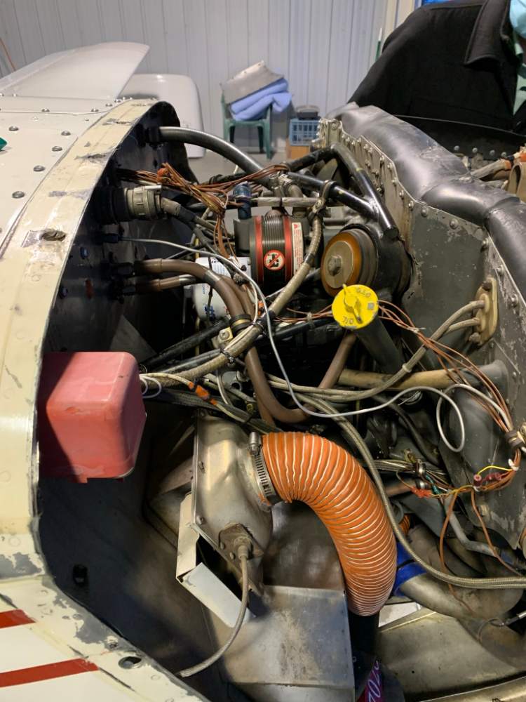
Our '76F originally had the SoS box mounted on the cabin side of the firewall. The last time an A&P/IA worked on it (about 10 years ago), he determined that was a stupid location, and he moved it to the engine side, right above the heater inlet. It's the red box at the lower left of the attached photo. I was a little taken aback by the move, as the mechanic didn't ask us about it before doing so. Apparently it was just obvious to him that it should be moved. A "minor mod" in his eyes, and documented, so the legal box is checked. Certainly easier to work on now, but that hasn't actually happened - it's been happily doing its thing with no issues ever since. If nothing else, that's anecdotal evidence that the new location is no worse than original.
-
To be clear, I wouldn't balk at buying an airplane whose logs simply say this A/D is not applicable by serial number, and I doubt many others would either. In our case, though, our A&P is coming out anyway to inspect the overhauled fuel pump we're installing, so it's kind of a no-brainer to have him take a quick look and note in the logbook that the airplane was inspected for bad elevator counterweights as well. You could do that at your next annual if you choose and it probably wouldn't cost you anything extra. I'd feel differently about asking an A&P to perform a formal inspection if doing so required disassembling anything, but it doesn't in this case - a quick look is sufficient. As an example of what I'm getting at, though... would you feel comfortable buying my airplane if you reviewed its logs and saw the electric landing gear actuator had never been disassembled and inspected for worn gears? None of SB M20-190B or AD 75-04-09 or AD 75-23-04 apply to our airplane, because neither its serial number nor the ITT LA11C2114 actuator installed in it are on any of the callout lists in those documents. If you ask around though, most Mooney-savvy shops and owners would tell you it would be foolish not to at least occasionally inspect the actuator, and that you should be skeptical of buying an airplane that's never had the inspection done. If anyone is going to perform that inspection, you should probably have them log it, whether the AD is truly applicable or not. My attitude toward this new elevator counterweight AD is similar.
-
Correct, Mooney/the FAA is worried elevators from the affected models may have been installed on other airplanes. Dunno if hybrid weights can be installed on beaded-skin elevators, but I wonder if anyone ever replaced a damaged beaded-skin elevator with a salvaged smooth-skin elevator, via 337 (or just not asking questions they don't want answers to). Our airplane - like yours - has the beaded skin elevators, not smooth. But I'm going to have a friendly A&P sign off an AD inspection anyway. Given the weasel words in the associated SB, I just don't want to get into an argument with some future buyer or IA who thinks the AD inspection should have been performed. Easier to just point to the logbook entry and say, "Yes, this airplane has been inspected in accordance with that AD".
-
Can KX-155 drive both a KI-206 and a GI-275?
Vance Harral replied to Flash's topic in Avionics/Panel Discussion
No argument there, but the OP wanted to retain his KI-209. If the KI-209 is removed (or just bypassed and disabled), and the KX-155 connected directly to the GI-275 instead, that would certainly work, and eliminates the mechanical switch. Fair point that there's no drawing which shows a GI-275 driving analog autopilot deviation signals to a switch instead of directly to an autopilot. I hypothesize a good avionics shop or freelancer might be comfortable claiming the GI-275's deviation outputs are just an "omni output" in accordance with older autopilot installation manuals - since they conform to the analog voltage standard - and therefore pronouncing it kosher to connect them to an approved autopilot via a completely passive switch that presents an equal or higher impedance load to the GI-275 under all conditions. Driving two CDIs from a KX-155 seems a little sketchier, and I hypothesize fewer installers would put their name on something like that. But it's not my opinion that matters. These are good questions for the OP to ask an installer. -
Can KX-155 drive both a KI-206 and a GI-275?
Vance Harral replied to Flash's topic in Avionics/Panel Discussion
If the goal is to run the autopilot from NAV2, seems like the simpler and better way to achieve it is to just install a DPDT switch that selects between the GI-275 and KI-209 analog deviation wire pairs, for the autopilot's deviation inputs. Label it "autopilot nav source". Set to NAV1 for IFD-540/GI-275, NAV2 for KX-155/KI-209. This sort of setup used to be common, e.g. our old Brittain autopilot setup has a NAV 1/2 select. You don't say what autopilot you have, but if it's a somewhat older model, the installation manual almost certainly contains provisions for a nav input select like this. Materials cost would be a few bucks for the switch and a couple feet of 22AWG wire. Probably less than 1 hour of labor to install, modulo the usual "Mooney tax" for difficulty accessing stuff behind the panel. The only downside is that the switch becomes a potential failure point, so spend a few bucks extra for a high-MTBF unit. Based on what N231BN says, sounds like it's technically possible to drive two CDIs from a single KX-155. But I still think the pilot interface for that is confusing, and the potential for error high (you say you don't intend to set the OBS knobs differently on the two indicators, but sooner or later that will happen). Note also that you may or may not get an avionics shop to agree to perform the work. Some shops won't install anything on a certified airplane for which there is a not a specific drawing in the installation manual for the devices being connected, and there aren't any "dual CDI output" drawings for nav radios. -
Can KX-155 drive both a KI-206 and a GI-275?
Vance Harral replied to Flash's topic in Avionics/Panel Discussion
Without looking at the installation manuals, I'm going to opine that you don't want to do this, because the KI-206 and GI-275 have independent OBS "knobs" (physical in the case of the KI-106, virtual for the GI-275). Not sure what you're expecting to see on dual CDIs driven from the same source, if they don't have the same OBS knob setting. Lots of potential for confusion and failure, and seems like a bad idea. -
Based on the picture you posted, your M20F is the same vintage as ours, with the early-J-style "6-pack" (actually 8-pack) round instruments panel. Having just finished a dual G5 installation in our airplane last month, during which we removed a GI-106A CDI indicator, here are some tidbits for your consideration: First, yes, dual G5s will fit in that panel. If you cut a whole new panel, you can do almost anything you want, including flush-mounting dual G5s, shifting them slightly, whatever. If you don't, though, you'll need to slightly file out the AI and DG holes of your existing panel to fit both G5s. This procedure is described in the installation manual, and isn't too a big deal. But per the manual, if you oval out the mounting holes this way, you're also supposed to buy or fabricate a couple of aluminum plates to more securely hold the instruments, as well as installing a slightly longer capture screw in the G5 unit itself. Post-installation, we've realized the push/twist control knob for the lower G5 HSI is close enough to the yoke shaft that it's a bit awkward to use with one's right hand. Easier if you reach over with the left hand, but that also feels a bit awkward to this right-handed bloke. That's a very minor gripe, though - absolutely not a deal killer. A G5 HSI can only display vertical/lateral needles for once source at a time. However, it can receive nav data from multiple ARINC-429-capable sources, via the GAD29B that is usually installed with it. If you have two "modern" NAV/GPS radios (e.g. Garmin 430W or better), you can switch the HSI display between them, and/or display bearing pointers for a secondary source while showing needles for the primary source. Whether or not this is a good idea is debatable. Personally, I prefer separate indicators. On a related note, I kinda miss the dedicated OBS knob of the GI-106A we removed. Setting an OBS course on a G5 HSI requires a "click-twist-click-twist" action, rather than a single twist. People who only navigate using GPS waypoint sequencing won't care about this. I only miss it because I'm old, and I like to pull CFI tricks on instrument students that require VOR navigation and/or OBS mode on the GPS. G5 vs. GI-275 is debated frequently. Not a slam dunk either way, IMO. My causal observation is that cost aside, guys with good eyesight favor the higher resolution display of the GI-275; while those not so blessed have a slight preference for the physically larger display of the G5, even though it has fewer pixels. Hope that helps.
-
ADs are no longer mailed to aircraft owners, though that used to happen. As I understand it, in the modern era, you're expected to sign up for e-mail notifications at https://public.govdelivery.com/accounts/USFAARGL/subscriber/new?pop=t. I believe the FAA's position is that failure to do so is a violation of https://www.ecfr.gov/current/title-14/chapter-I/subchapter-C/part-39/section-39.7. Please note that I'm not arguing this is a reasonable position for the FAA to take, just explaining my understanding. In practice, being a member of your aircraft's "type club" is usually sufficient to be informed. Regularly checking here on Mooneyspace is in certainly in the spirit of that.
-
1992 M20J Panel Upgrade / Advice
Vance Harral replied to gevertex's topic in Modern Mooney Discussion
Internet says GNX375 is 10.85" deep with backshell connectors. That is definitely not going to fit at the top of an M20J panel as depicted in the OP's layout. As carusoam says, the center tube that comes down the windshield branches out just below the glareshield, and winds up running behind the left radio stack in a manner that limits the depth of avionics that can be placed at the top of that stack. You are going to have to put that GNX375 either below the G3X 7" display (if it will fit below it), or over in the right side stack. -
Weldon 8163A fuel pump availability
Vance Harral replied to Vance Harral's topic in Vintage Mooneys (pre-J models)
Again, thanks for all the replies so far. For what it's worth regarding the recommendations to use C&J, we did attempt to contact them for a quote, but they have not returned our phone call in almost 2 full business days. Further discussion with Aeromotors reveals they can also provide us with fresh leather washers and O-rings for the attach fittings (see https://mooneyspace.com/topic/41467-fuel-line-gasket-an6291-6-or-alternative/), so Aeromotors remains our plan. -
Weldon 8163A fuel pump availability
Vance Harral replied to Vance Harral's topic in Vintage Mooneys (pre-J models)
Thanks for the replies so far. We called Aeromotors. They don't have any exchange units in stock, but their quoted price to overhaul our existing unit is the best we've found so far. They also have authorization to make internal components (including armatures), unlike some other overhaulers; and returned units come with an 8130-3. So that's likely the way we'll go, unless someone else reports something clever here. -
Airplane exhibited the classic "dripping from the fuel pump weep port" this week. The crummy thing only gave us 19 years of service before the internal seals failed. Our airplane was "upgraded" from the original Dukes pump to the Weldon 8163A per a Mooney factory drawing, back in 2004. As a partnership with a maintenance fund, our preference is to purchase new, or overhaul/exchange Weldon, to minimize down time. Trouble is, looks like another round of old airplane/supply chain issues/whatever. Aircraft Spruce says no stock until April. Air Power says no stock until "probably" March. Backordered at Aviation Parts Executive. No luck at McFarlane or LASAR, though everybody is "checking on it". We're waiting on a call back from Weldon themselves, but I don't expect that to bear fruit. Haven't looked into going back to the Dukes pump - not particularly inclined to, but might consider it. Anyway, it's looking more and more like our best option is to send off our existing pump to one of the overhaul shops: Aeromotors or QAA, but that's a 3-ish week turnaround time, and we were hoping for something more like instant gratification. Anyone got any leads? If not, anyone have any contradictory recommendations to Aeromotors, which in searching old threads seems to be the most popular overhauler?
-
Same for me, for what that's worth. My most recent experience took nearly 3 full weeks to get a reply on the topic I mentioned above about "true heading". To be fair, this took place leading up to and over the Christmas holidays.
-
Engine Monitor Preference
Vance Harral replied to ArrowBerry's topic in Vintage Mooneys (pre-J models)
My hypothesis about the EI connector failures is not so much that crimping is hard and soldering would be easier/better. It's that the particularly large "quick connect" spades they chose were not a good solution, independent of whether those connectors were crimped or soldered. For one thing, they are heavier than other choices, which is an issue in a high vibration environment like the engine compartment of a piston airplane. For another, they were arguably the worst of all worlds: supposedly "quick" to connect and disconnect, but even using "two drops of oil" per the installation manual, I always found them to be difficult to pull apart on occasions when I wished to do so. Difficult enough to require tools, which increases the likelihood of stressing the wire to pull them apart. If I had it to do all over again without the benefit of the OLC connectors, I'd likely use small, lightweight butt crimp splices, and just leave plenty of spare wire to cut and re-splice a half dozen times or so over the life of the airplane. But I make no claim this was/is an "obvious" solution, and I haven't done any engineering analysis to support that statement. Again, the OLC connectors EI now ships with their product seem to be a good, reliable solution. Haven't had any problems since moving to them. If you haven't seen these gizmos, they're little, lightweight barrel connectors, with tiny hex screws that hold the wire in the connector: https://iflyei.com/product/olc-2/ The fact that they have moving parts (the screws) is interesting, but they seem to work very well, at least to the extent my experience represents a single data point. -
Engine Monitor Preference
Vance Harral replied to ArrowBerry's topic in Vintage Mooneys (pre-J models)
Right. You guys chose a connector that had tons of problems in the field, as evidenced by the fact you had to employ someone full time just to answer questions about them. Then you staked out a position for a long time that issues with the connectors were "likely" due to improper installation, citing a few anecdotes as evidence. Look, I get it. Lots of people crimp stuff with a four dollar crimp tool from Autozone, don't ensure the wire shows through the witness hole before ham-fisting it shut, bend the connector while crimping, etc. etc. etc. There are lots of failure modes. So maybe don't choose those connectors in the first place for a product that requires widespread field installation? I'm an engineer too. When I choose components for my company's products, one of the criteria is reasonable performance in the field across a broad variety of skill sets, without a support engineer standing next to the installer and holding their hand. Why EI didn't just tell me at the time that there were lots of problems with spade connectors - maybe installer induced - and that maybe I should consider soldering them or whatever, is lost to history. Instead, I was specifically told at the time there were "no widespread installation problems". Now I know that's not true, and that's why I'm being so grumpy about it. You're admitting right now that wasn't the case. There's a good reason lots of companies - including now you - avoid spade connectors in difficult environments. You guys were just late to the party in figuring that out, but that's not an unforgivable sin. I'm not complaining about the engineering history, I'm complaining about transparency and customer support. I do appreciate the reply, and I understand you're just trying to do right by your company. I like EI, and want them to succeed. I don't want you to get run off of Mooneyspace or other public forums. What I'm trying to communicate to you as a fan of the company is, EI has an established history of connector problems. Claiming that's not true, and/or blaming the problem on your customers, is not a winning strategy. Were I running the EI PR department, the story would go like this: "We originally chose spade connectors based on widespread industry use, but it turns out those were not a good solution for our particular application, due to a combination of installation issues and the environment in which they operate. While we wish we'd been able to foresee that problem, we acknowledged the issue, and designed a new connector to resolve it. We encourage our customers who hear about connector problems to understand this history, and the steps we've taken to fix it." Instead, we get, "Yeah, it was all the installers' fault, and we were forced to design around their incompetence". Again, not a winning strategy. Even if that's what you really believe. Even if it is, in fact, somewhat or even largely true. The main thing I'll say in closing is, we haven't had a lick of connector trouble since moving to the new style connector; and because of that, I'm still happy to recommend EI products to friends and colleagues. -
Your Personal VFR Weather Minimums (poll)
Vance Harral replied to 201er's topic in Miscellaneous Aviation Talk
That's exactly what I'm describing in my story: a cold-call pop-up. And Rich is describing departure from an airport with no instrument approaches. Both of these things constrain the services ATC can provide, in a manner that's entirely on the pilot. My story is not a complaint about Denver Approach. I've found them to be very accommodating over the years. -
Engine Monitor Preference
Vance Harral replied to ArrowBerry's topic in Vintage Mooneys (pre-J models)
I really like EI and this comment is not intended to bash them. That said, @oregon87, you need to be aware that EI has a history of connector problems, and at least in my personal experience, they have not always been honest about it. We installed a UBG-16 in 2009 and I'm glad we did, but over the course of the next several years, I had no less than 5 EGT/CHT drop-outs due to broken thermocouple wires right at the quick-connectors for the probes. I assure you these were installed exactly in accordance with the instructions: wire doubled before crimping, two drops of oil on the spade, wires secured, but not "overtightened" per the installation manual. Still, continual breaks. I contacted EI both in writing and by phone, cordially, on a couple of occasions. I politely asked if this was a known problem, and if they could offer any guidance or assistance. I was told, in essence, "This problem is particular to you, we know of no chronic problems with our connectors. You must be installing them wrong." About a year after I gave up complaining and resigned myself to ordering a large batch of spade connectors and replacing them regularly ( I still have a dozen in my spare parts bin), EI announced their "new and improved" OLC-1 connector. Obviously, I raised an eyebrow at this: you guys wouldn't have redesigned the connector unless the previous solution had a problem. The OLC-1 completely resolved our problems with wires breaking, so good on EI. Nothing wrong with improving a product after lots of field test. But even though it was over a decade ago, I'm still salty about being told the problem was with me/my shop, when in fact it was a design flaw all along. After a few years of working with the OLC-1 and noting that it was reliable, but arguably a little difficult to install, EI came out with the OLC-2. Same concept, but independent set screws for each wire. Another improvement, so good on ya', but yet another indication that the connectors were an evolving solution. So given this history of continually updating your connector design, it just rings a little hollow to say here in public that "to see numerous issues with a single aircraft would be exceedingly rare". That just not true, dude. I'm living proof. -
Back to the "poor man's battery capacity test", purchase of a not-too-expensive clamp-on ammeter and a little data gathering is an eye opener for more than just checking battery health. Having recently been through a DIY G5 HSI installation, we performed the load test described in the installation manual, and it was really helpful in understanding just what kind of load each circuit in the aircraft presents. I previously had only guesses about this, and a load-shedding plan based on them. Some of my guesses were right: obviously pitot heat and incandescent external lights use a lot of juice. But other devices I planned to turn off in the event of an electrical failure turned out to be a bad tradeoff: lots of distraction in not having the equipment, in exchange for only 1-2 minutes of additional operating time before the battery (assuming its healthy) has bled out 80% of its rated capacity.
-
Your Personal VFR Weather Minimums (poll)
Vance Harral replied to 201er's topic in Miscellaneous Aviation Talk
I've had generally the same experience, though explained to me by ATC in different terms. After flying locally for about two decades, I'm comfortable departing VFR with scattered/broken at 1500-2000' AGL for various reasons: simple pattern work, scoot out underneath to better weather, etc. Once or twice I've tried to pick up an pop-up IFR in those conditions - for convenience moreso than safety - and Denver Approach wants you at 7000' MSL (ish) before they'll issue. That's not actually the bottom of the MVA (all of metro Denver has a "Diverse Vector Area"), but I think operationally they just don't want to deal with low traffic on a pop-up. Anyway, KBJC is up on a mesa, about 700' higher than everything else around here, and official pattern altitude is 6700, so "get to KBJC pattern altitude first" sounds about right. To be clear, I'm not advocating scud running. One of the reasons I've tried to pick up an airborne IFR clearance like this, is so I can tell my instrument students real-world stories about the problems departing VFR and trying to pick up a clearance while airborne. It's certainly reasonable to do this in a lot of situations, but marginal conditions over your departure airport isn't really one of them. Simultaneously dodging clouds to stay VFR while trying to negotiate and copy a clearance is pretty high workload with two pilots, and borderline foolish by yourself. Fortunately, the temptation to do this seems to be waning in the modern era, when you can get a hold of clearance delivery via cellphone at nearly any airport, even out in the boonies. That doesn't help at KBDU, though, where there are no instrument approaches, no TERPs survey, and therefore no way to depart IFR. KBDU is a fine little airport, but I don't recommend it to GA traveling tourists. Between the inability to get in/out IFR, higher proximity to mountain rotor, and much higher likelihood of noise complaints, it just seems like a poor tradeoff to me. It's only a 15 minute drive to either KBJC or KLMO from there and self-serve fuel prices are the same or cheaper at those airports, so arguably difficult to justify choosing KBDU as a destination airport. Arrive at KLMO if you want a small airport experience, KBJC if you want the opposite; and by all means, drive or fly down to KBDU on a nice weather day if you like, for a glider ride or aerobatic flight in a Citabria. -
Your Personal VFR Weather Minimums (poll)
Vance Harral replied to 201er's topic in Miscellaneous Aviation Talk
If I take off from Longmont and can't see Pikes Peak by pattern altitude, I declare an emergency! -
I have an opinion on who can sign off the work, but I'll refrain from posting it, because @EricJ is correct that my opinion doesn't matter. Regardless of who performs the work and makes an entry in the logbook, though, note that avionics firmware upgrades often require printing a new version of the AFMS that accompanies the firmware update and putting it in the aircraft with the POH/AFM; as well as printing new ICAW documents (if any), and filing them with the aircraft records. If you don't do at least the former, you're technically unairworthy. This AFMS/ICAW paperwork requirement is often missed during firmware updates, even by good, responsible shops, so I can sort of understand why Garmin only wants their (presumably trained) dealers to do the work. But they have little room to be high-and-mighty about it. Among other reasons, @Ragsf15e is right to complain about the details of the IGRF error message. There is a "Revision 8" of the AFMS that accompanies the v8.00 firmware, but the table of error messages on its last page still says "Magnetic field database out of date", rather than "Magnetometer IGRF data out of date". Looks like the workflow at Garmin let that discrepancy slip through.
-
I am presently in a "discussion" with Garmin Aviation Support about how the G5 uses magnetic deviation data, and the person responding to my inquiries keeps bringing up the IGRF database. He is not doing a very good job, IMO, of explaining what this is used for. I'm hoping maybe the collective wisdom of Mooneyspace can shed some light on this, and it seems germane to this thread. In general, magnetic variation data - which is what I understand the IGRF to contain - is used to calculate True Heading given Magnetic Heading. I can see True Heading being part of an AHRS compensation algorithm, though I don't understand the details. But what prompted my query to Garmin Aviation Support was a statement in Section 1.4.1.2 of the latest version of the G5 Pilot's Guide at https://static.garmin.com/pumac/190-01112-12_j.pdf; which says, "The G5 corrects for shifts and variations in the Earth’s magnetic field by applying the Magnetic Field Variation Database." That section of the Manual is titled "G5 Heading", and the implication is that the G5 uses magnetic variation as part of its heading algorithm, i.e. that it does/could/might display true heading on its DG/HSI page, rather than magnetic heading. I thought to myself that surely that can't be the case, but wanted clarification from Garmin. So I asked them about it. The reply from Garmin Aviation Support about this - after a delay of over a month - was as follows: Thank you for contacting Garmin International. The G5 can display both. When the GMU is connected, the G5 will display magnetic heading. If that connection is lost, then it will provide True Heading provided by GPS track information. This video further explains IGRF data and what we do with that: https://www.youtube.com/watch?v=fapV6WClc7Y&t=1s The first part of the response make sense: when a GMU11 magnetometer is connected to a G5, its DG/HSI page displays magnetic heading. As far as I know, the system has no need of IGRF (variation) data to do this, but I'm ready to be corrected on that if someone knows differently. Again, I can see how the AHRS compensation algorithm might need true heading as an input, and therefore need variation data to compute it from magnetic heading, but that's independent of the heading displayed on the DG/HSI page The second part of the response, regarding the G5 showing "True Heading", makes no sense to me. If a magnetometer is not connected to the G5, I don't see how it could possibly show any kind of heading, either magnetic or true. I do understand that the G5 shows GPS track without a magnetometer (indeed, our first G5 was installed standalone as an AI and that's how it worked until we installed the second one as an HSI). But track != heading, and I'm starting to think whoever wrote the manual either doesn't understand that, or is a poor communicator. I wrote back to Garmin Aviation Support and asked, "If an aircraft equipped with a G5, but without a GMU magnetometer, is pointed true north; and flying into a headwind so strong that its ground track is actually true south; what 'heading' will the G5 display?" That was a week ago, still waiting for a response.


