-
Posts
1,416 -
Joined
-
Last visited
-
Days Won
3
Everything posted by Vance Harral
-
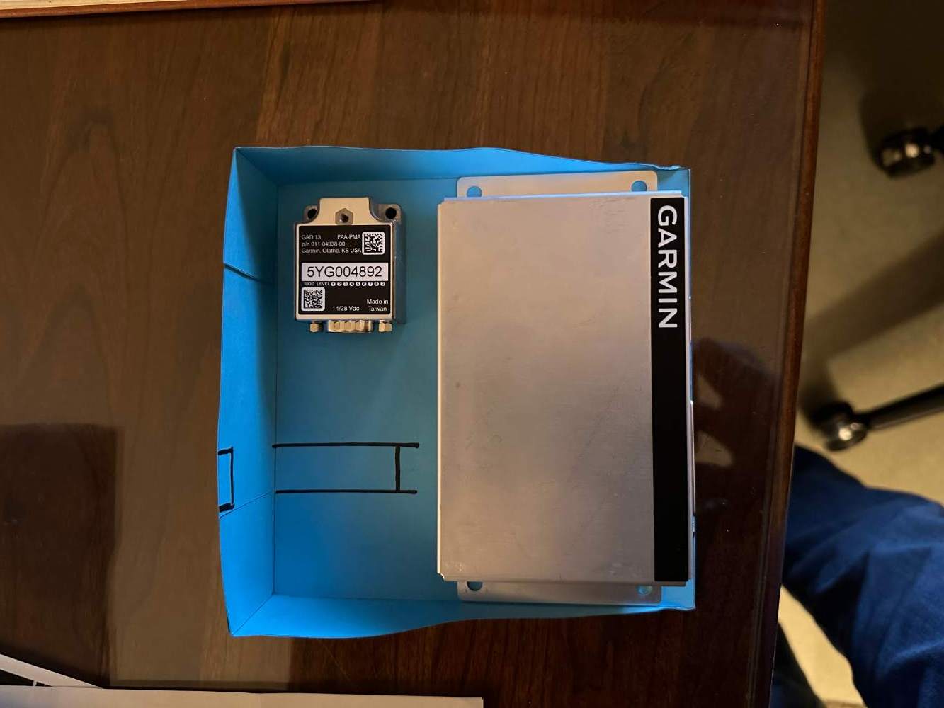
We built a little shelf and mounted it behind a blank panel in the right side radio stack, in a location where we had about 1" vertical of unused radio space. The attached pics show a card stock mock-up of the shelf, which was later fabricated from aircraft aluminum. There is room for both the GAD29 and the GAD13. It was certainly more of a pain getting things to fit behind the radio stack than in the tail cone, but once you solve the physical mounting, the electrical wiring is a lot simpler - no need to pull interior panels and run wiring down the side of the cabin.
-

Throttle cable rubbing on prop governor
Vance Harral replied to Vance Harral's topic in Vintage Mooneys (pre-J models)
Thanks for the pictures, sir. I looked at it some more this afternoon, and I'm coming to the conclusion that whether the cable rests on the governor or not appears to simply be a function of it's exact length. The cable is secured at the firewall, and of course right at the point where it transitions to a metal pushrod. Everything between is "slack", but the cable is fairly rigid, so a longer cable bows a little more and tends to not touch the governor, and a shorter cable bows a little less and tends to touch. I figured out today that a zip tie or large MS21919 clamp around the body of the prop governor would hold the cable against the governor the way it used to sit, where it doesn't rub against the hard corner of the governor flange. I'm going to talk that option over with my mechanic. -
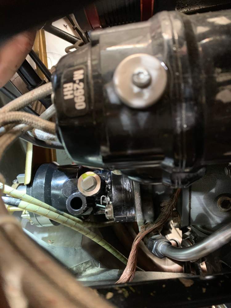
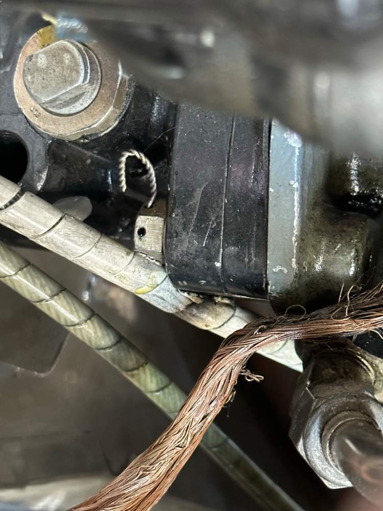
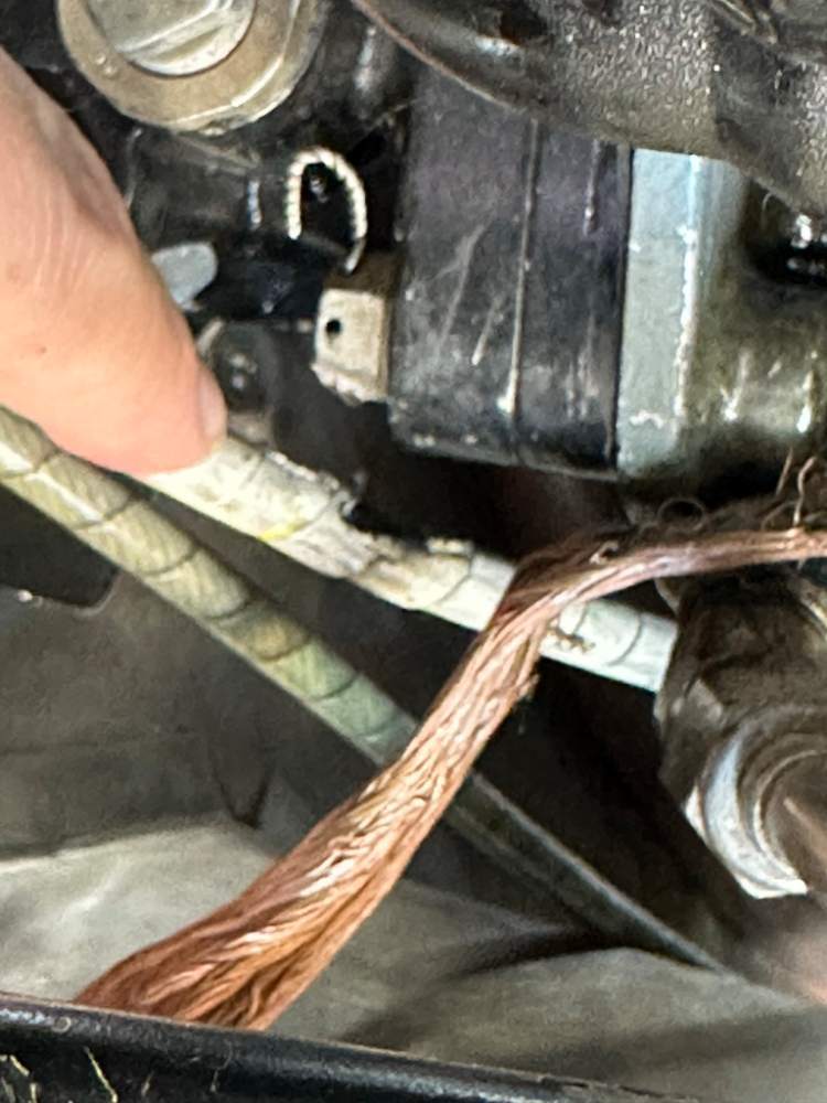
Hoping for some mechanics' wisdom and maybe a photo or two from another airplane. The routing of the throttle cable in our 1976 M20F passes by, and touches, the prop governor. The first photo below is one I found from one of our annuals back in 2019. You can see the cable touching the governor, but it is protected by PTFE spiral wrap, and it follows a relatively "soft" edge. The second and third photos are what I found yesterday during an oil change. At some point, for reasons unknown to me, the interference between the cable and the governor moved to a "hard" corner of the governor and has experienced significant wear. The good news for us is that the sacrificial spiral wrap did its job. The cable itself is not meaningfully damaged, it just has the slightest of witness marks on the sheath. So we caught this in time. The question is, what to do about it? The classic solution would be an Adel clamp, perhaps on a standoff, but the only bolt it could attach to in that area is one that secures the prop governor. I'm disinclined to do that. The IPC doesn't provide any detail on cable routing in this area. Would appreciate any comments/tips on how to address this.
-
Generally agree with everything Ross said, but one extra subtlety to understand is that if the hot engine has effectively primed the cylinders by "boiling" fuel out of the lines from (and in some cases to) the flow divider, then you have "bubbles" (vapor bubbles and/or air) in the lines between the fuel servo and the injectors, which contain no fuel. As fresh fuel flows from the tanks, through the pumps, and out toward the engine, these bubbles are pushed into the injectors, resulting in a temporarily incombustible mixture due to lack of fuel. The hope is that when that happens, your engine has developed sufficient momentum to keep turning, until more fuel moves through the lines to again create a combustible mixture. This is why even a successful hot start involves a certain amount of coughing and sputtering. When it doesn't work out, and the engine fires but subsequently dies, that doesn't necessarily mean there was anything incorrect about your technique. The control mechanisms you have (throttle and mixture) operate on the fuel servo, not the intake ports of the cylinders. So anything you do with throttle and mixture during a hot start is removed in time/space from the immediate problem at the injector ports. This is one reason having a strong battery and starter help with hot starts: they increase the momentum of the engine during start, making it more likely to keep turning while the system works its way though the bubbles. I also sometimes turn on the fuel pump if it sounds like the engine is about to die, but it's unclear to me how much that actually helps.
-

My attitude indicator is starting to fail
Vance Harral replied to M20 Ogler's topic in General Mooney Talk
Alignment time on the G5 is very fast, and it aligns itself pretty rapidly even in flight. I know this because the flight school I teach at has dual G5s in every single one of their airplanes, and I frequently turn them off for partial panel training. Attitude indication comes back very quickly, though it takes longer for the unit to establish communication with the GFC500 autopilot and turn off the red Xs on the autopilot scoreboard. -
The first engine start in that video that takes place within the first minute is interesting - the one he calls "kind of a dirty start". Note that after that first start he "runs it up" and "clears it out", as he does in every subsequent run. I don't think all the other starts in that video are interesting. The amount of time the engine is stopped in these subsequent demos is about 20 seconds, 30 seconds, 60 seconds, 5 seconds, and 15 seconds. He talks about fuel "percolating" in the flow divider during those shutdowns, but he's not not actually waiting long enough for that to happen. The fresh fuel flowing through the system when he's running the engine and "clearing it out" cools the pump, flow divider, lines, etc. Once the engine is stopped, it takes several minutes for the hot cylinders to convectively reheat the cooled components and the fuel inside them, and cause the problem we're trying to solve. In summary: good description of the problem, good discussion of theory, but this circus trick of restarting the "hot" engine just a few seconds after shutting it down isn't very relevant to the hot start problem - it's just indirectly telling you not to let the problem occur in the first place.
-

My attitude indicator is starting to fail
Vance Harral replied to M20 Ogler's topic in General Mooney Talk
... or in some cases a "blind" turn coordinator that is behind the panel, but that has no glass face you can see from the pilot side. In any case, N201MKTurbo is correct, the Brittain autopilot is a rate-based autopilot, not attitude-based. It is not connected in any way to your attitude indicator. -
I actually wrote "does absolutely nothing" in my first draft. But it does pressurize the fuel between the pump and fuel servo, which "might" have a few vapor bubbles due to heat cooking that line (unlikely given that that hose is below the hot parts of the engine, and heat rises). Even if there are vapor bubbles there, the fuel pump pressure is unlikely to collapse them, and even if it did, that's well upstream from the part of the system that makes hot starts difficult. So I guess I'd amend my comments to say, "very little in theory, and nothing in practice".
-
Every time I see this advice given without qualification of engine type, I feel obliged to point out that it's poorly understood. First, this practice does very little in fuel-injected Lycomings with RSA fuel servos. That's the power plant for all the "vintage" fuel-injected Mooneys (M20E, M20F, M20J), and also for some of the later big-bore models as well. In the RSA fuel injection system, fuel has nowhere to go when the mixture is at idle cutoff. There is no flow to move vapor bubbles anywhere or cool anything, no matter how much pressure the pump provides. Therefore, the only thing you're doing is pressurizing the system between the pump and the fuel servo. The 20-ish psi provided by the pump is very unlikely to collapse any vapor bubbles that have formed there, and even it if did, everything downstream of the fuel servo is unaffected. Things are more interesting in the Continental system, which has a vapor return line to the tanks. Running high boost with ICO mixture in these system does cause fuel to flow through the pump, both cooling the pump and moving vapor bubbles upstream of and inside the pump out of the system. There is some residual cooling effect just downstream of the pump, but once you get very far away from there, the system is similar to the Lycoming. However, the pressure provided by high boost in Continental installations is nearly double that of the Lycoming pump, and that higher pressure probably provides some benefit as well. I don't operate a Continental, but this advice to run high boost for a minute prior to hot start is so well accepted that it almost certainly has some benefit. In the mean time, though, Lycoming operators try this to no effect, and confusion abounds. Anyone wanting to understand the mechanics of hot starts would do well to first understand the fuel injection system in their particular engine. You can see schematic diagrams of both, side-by-side, at https://aviation.stackexchange.com/questions/71333/what-is-the-main-difference-between-continental-fuel-injection-system-and-ben In summary, Fly Boomer's advice is good for Continentals, and harmless-but-ineffective in Lycomings.
-

Looking for M20J airspeed safety switch
Vance Harral replied to PierreL's topic in General Mooney Talk
I attended that same webinar, and came away from it somewhat pessimistic about the ability of VARMA to do much good for Mooney owners, because Mooney is at least theoretically still in the business of supplying parts. Even when the part in question was actually manufactured by someone other than Mooney, it sometimes has a Mooney part number in the IPC, and I think that's going to be a problem. To wit: the guys running the webinar stressed that you won't get a VARMA letter for a part which is purportedly available from the OEM of your airplane, because the FAA doesn't want to be seen as taking business away from the manufacturer. They framed it as "you won't get a VARMA letter for a part you just think is too expensive from the OEM". I get that, but during the Q&A, there were apparently dozens of people who had the same question as me: namely, what if a part is only theoretically available from the OEM, but not actually available in practice? This is the situation we have with lots of Mooney parts today: intake boots, yoke shafts, etc. If you actually ask Mooney to sell you one of these things, you often get a song and dance about indefinite lead times, the need to accumulate enough orders to justify making a run of parts, and so on. Your aircraft could easily be AOG for months waiting on such a part. I was disappointed that the VARMA guy who answered the question seemed to be unaware of this problem. He seemed a little surprised by the question itself. He tried to give a hopeful answer, but it was a vague thing like, "Oh, well, I would like to think that's the kind of thing we could work out a solution for." It was clear they hadn't really considered this theoretical vs. actual availability problem while building the VARMA framework. Anyway, maybe I'm being too pessimistic. But the way I see this going down is that Mooney isn't going to admit they can't supply parts until/unless they actually go bankrupt, and without such an admission, the FAA isn't going to give you a VARMA letter for anything with a Mooney part number in the IPC. -
There is not a mac port of the DRS-1 software. Mac users typically run Windows software via Bootcamp or Parallels to solve this sort of problem.
-
This GI-106A has been sitting in a box for about 9 months, since our G5 HSI upgrade. No 8130 provided, but as the cliche goes, it was "working flawlessly when removed", I personally think that phrase always sounds a bit sketchy, but it's true in this case. It was installed new in 2012, and gave us 10 years and about 1000 hours of faithful service with nary a hiccup. The unit is cosmetically pristine - no scratches in the glass or paint, not even on the OBS knob. Included in the deal is a connector and cable (pictured), but note that the high-density garmin pins which mate to your GNS/GTN connector were cut off during removal. Any reputable avionics shop will have the pins and the crimp tool to install them. But if you're more of a DIY-under-adult-supervision guy/gal, you can get what you need from SteinAir: a set of 25 pins is $15, and you'll need their $38 crimping tool and $20 High Density Positioner if you don't already have one. Asking price for these indicators on eBay seems to be about $1500, but I'm unconvinced that's the real value, as the used market is glutted with upgraders like ourselves. I'd also rather sell it to someone on Mooneyspace for a little under market rate. So I'm posting it at $1250. I'll cover reasonable shipping costs, you can pitch in if you want quick delivery and/or high-dollar insurance. Feel free to post questions here in this thread, and/or PM me.
-

Seat rises and falls with gear swing?
Vance Harral replied to Mcstealth's topic in Vintage Mooneys (pre-J models)
That's different than my experience, so not sure what to tell you. I agree it warrants putting the airplane on jacks, pulling the belly panels and taking a look at what's actually happening. -
Yes, those of us with the superior quadrant-design engine controls continue to pity the poor majority of sad Mooney owners who must make do with push/pull controls and their infernal vernier knobs.
-
Not that I know of. But the best CB approach to maintaining the existing panels is a bin full of replacement screws (a lifetime supply is cheap); a lightweight, clutched drill driver with a good Phillips bit; a cotter key hook tool to align the Tinnerman nuts; and a paint job you don't care much about. When it's time to remove the panels, use the driver to spin the screws out, and throw them away. To reassemble, pull new screws out of the bin, install a couple to hold the panel in place and then use the alignment tool to verify all the Tinnermans are in place, then go to town with the driver. Yes, you'll wind up with occasional scratches in the paint this way, even if you're careful. For many of us, that's entirely worth the time and frustration saved.
-
47U is correct, the highest frequency sampling for the MUX-8A is every 6 seconds. This is fine for monitoring long-term trends, but won't work for Savvy's FEMA analysis that attempts to identify early signs of exhaust valve failure from high-frequency "wiggles" in EGT data. Speaking of Savvy, you can upload the *.CSV files you get from MUX-8A downloads directly to their online analyzer, and it handles that fine - no need to import into Excel and make your own graphs. We don't have MP or RPM on our UBG-16, but we did add fuel flow, for the same reasons 47U mentions - analysis of EGT/CHT behavior is essentially meaningless without an indication of what power the engine is operating at. In our case, we felt fuel flow was good enough, but obviously having MP and RPM as well provides a clearer picture. Speaking of fuel flow, here's a cool story about EI customer support: our airplane already had a Shadin fuel totalizer, so we didn't purchase another fuel flow transducer along with the EI fuel flow module. I reasoned that I could just adjust the fuel flow module to match the K-factor of the transducer for our existing Shadin, and wire it in parallel with the Shadin wiring. That idea was sound, but it turns out the potentiometer on the fuel flow module doesn't have enough range to match the K factor of the transducer for the Shadin. When I was working with EI customer support to understand this, they immediately understood what I was trying to do, and built a custom fuel flow module for me and exchanged it for the unit I had purchased, for free. This sort of thing is basically unheard of in the modern era of electronics. It's made me a lifelong fan, though I confess the bloom is slightly off the rose for me in recent years. I haven't had the same frustrating experience as 47U regarding data download, we've been trouble free. On the hardware side, there's a trick to this: the MUX-8A uses an RS-232 interface which is now ancient. Downloading data to a modern computer requires an RS-232-to-USB adapter. Many of the inexpensive ones are "junk hardware" that have poor signal integrity, and assume the computers on either side of the link are going to mitigate that via checksum/resend algorithms which the MUX-8A doesn't employ. If you buy a higher quality adapter, e.g. https://www.amazon.com/KeySpan-High-Speed-Serial-Adapter/dp/B0000510Y4, that eliminates the glitching. EI was pretty clear about this back in the day, but now that the MUX-8A is old, information about it isn't nearly as prominent. On the software side, I don't understand the comment about the DRS-1 analysis software not being compatible with Windows 10. I got a new Windows 10 laptop earlier this year, and I installed DRS-1 on it and downloaded data from our MUX-8A just a couple of months ago. Might have something to do with the version of software, I suppose. The latest version is available for download on EI's web site: https://iflyei.com/wp-content/uploads/EI-DRS-1-Software.zip One other bit of trivia: the MUX-8A contains an internal, battery-powered clock, which is set at the factory with the current day/time. That's how it timestamps data. The life of this battery is on the order of 10 years. When it fails, the timestamps in your data for every flight revert to some date in the long-past which the manufacturer of the internal clock IC set as the epoch, and this means you can't distinguish any flight from any other flight. We sent ours back to the EI for this problem. They "serviced" it for $300, which turns out in practice to mean they threw it away and sent us a brand new one for a 10% discount off retail price.
-
Depends on what year models you're talking about. The instrument panel, controls, and interior of a 1976 M20F are identical to that of a 1977 M20J. So much so that if you happen to have the former, you actually need the M20J parts and service manual to understand some of the interior assemblies. Not that this makes a major difference, just interesting trivia.
-
Opinions vary by airplane and operation, of course. I'm guessing an international 787 captain wouldn't call it "hard IFR" until cat III autoland is required. For me, in piston singles, the distinction is generally whether one actually needs to fly a standard instrument approach to land, vs. simply descending through an overcast on an airway or vector, and being cleared for a visual approach below. If I have to navigate IMC to the FAF, and especially if I'm still in the soup when I get there, I call that "hard IFR". My rationale for this isn't so much how close the conditions are to minimums for the approach. I think of it more in terms of how much VMC time I have to deal with a problem. Imagine you're in the clouds, the engine fails, and you glide down to visual conditions. If you have a couple of minutes to decide where to put it down once you can see, that's not hard IFR. If you only have a couple of seconds, it is.
-

Seat rises and falls with gear swing?
Vance Harral replied to Mcstealth's topic in Vintage Mooneys (pre-J models)
It will most certainly bug me if mine stops doing that! I actually think of the love tap on my butt as an extra "gear down and locked" indicator. -

Seat rises and falls with gear swing?
Vance Harral replied to Mcstealth's topic in Vintage Mooneys (pre-J models)
That's a good point. I guess it's not clear to me from the OP whether the movement is occurring at the end of extension and beginning of retraction (which I would consider normal), or at the end of retraction and beginning of extension (which I agree is more disconcerting). Per the service manual, the mains should not actually touch the bumper pad in the retracted position, so significant witness marks on the bumper pads might indicate a problem. Other things could hang up too, including the gear doors, though I'd think the gear doors themselves would flex before any significant flex in the belly pan as retraction completes. -

Seat rises and falls with gear swing?
Vance Harral replied to Mcstealth's topic in Vintage Mooneys (pre-J models)
20:1 gearing causes more force between the individual gears, subjecting them to greater wear over time. Eventually they wear to the point of jamming, and if they do, the emergency extension system isn't going to help you. This is discussed in a Mooney Service Bulletin, https://www.mooney.com/wp-content/uploads/2020/12/SBM20-190B.pdf Later model Mooneys with higher gear speeds and more weight/drag (due to additional gear doors) used actuators with 40:1 gears. The idea is that retrofitting these higher ratio gears to older actuators reduces the inter-gear force, allowing them to last much longer. -

Seat rises and falls with gear swing?
Vance Harral replied to Mcstealth's topic in Vintage Mooneys (pre-J models)
Well, hang on a minute... We've had this debate before in another thread, I guess it's not resolved. But I maintain that it's completely normal for the seat pan to flex a little when the gear locks into place on extension, and to correspondingly un-flex when it's raised. Our airplane has been doing this for the entire 20 years we've owned it, both with 20:1 and 40:1 gears in the actuator. The gear is correctly rigged per the service manual, and the belly pan is not cracked. Other Mooneys I've flown in exhibit this behavior as well. If you look at the attached photo of the actuator installed in the belly, it makes sense why this is true. In the photo, the motor is on the right, and the jackscrew assembly is on the left (red anodized structure). In the orientation of this photo, the rod that drives the nose gear is at the top of the jackscrew assembly, and the rod that drives the mains is at the bottom (both rod ends are out of the frame). When the gear are extended, the jackscrew assembly experiences compression, due to the springs on the nose and main gears. Look at how the jackscrew assembly mounts to the airframe to hold it in place. It is riveted to the belly pan directly under the pilot's seat. Accordingly, when the assembly is put in compression by the gear springs on extension, that force is translated to some degree to the belly pan. Unless the belly pan is perfectly rigid - which it's not even when new - the pilot will feel some degree of "push" in the seat. Obviously there are reasonable limits. It's one thing for the belly pan to gently flex a small amount and give the pilot a love tap, when the gear is extended due to the springs compressing. Quite another for the pilot to get a huge kick in the a** if the springs are bottoming out and the compression to flex the belly pan to the point of cracking. I can also believe that the specific geometries of individual airframes are such that some exhibit less butt-push than others. But bottom line, I don't think the mere presence of seat pan flex is unquestionable evidence something is wrong. -
We have a UBG-16 in our M20F (IO-360-A1A). We have high temp CHT limits set on all four cylinders at 390. We originally set them at 380, but found that was causing us to get an alarm during essentially every climbout in the summer. That was in turn training us to ignore the alarm, which is not a good thing, so we upped the limit. Turns out a 10 degree increase was all it took to almost entirely eliminate the nuisance alarms. In general, I expect CHTs to be in the high 300s on climbouts, and in the low 300s in cruise with the cowl flaps closed. We don't set low CHT limits. First, they'd go off on every engine start, and again that just trains you to ignore the alarm. Second, if a cylinder actually quit in flight, the resulting significant roughness would indicate what was happening way before any temperature alarm. We don't have any limits at all set for EGT. Absolute EGT values are generally uninteresting, particularly on a normally aspirated engine. We also don't enable any alarms for EGT or CHT differentials, or rates (We are unconcerned about "shock cooling"). This thread reminds me that I should probably set an alarm for high oil temp limit. The oil temp probe is a recent addition, and I haven't gotten around to re-programming the UBG since it was installed. The factory gauge redline is 245, but I'm inclined to set the alarm at 225, which is the top of the green arc.
-

Fire Extinguisher underweight
Vance Harral replied to mooneyflyer's topic in Modern Mooney Discussion
You'd think the fact that the name of the company was Nukem mighta given it away? -

General Thoughts and Guidance on Aircraft Partnerships
Vance Harral replied to ValkyrieRider's topic in General Mooney Talk
For better or worse, our arrangement has a somewhat "generic" LLC Operating Agreement, which explicitly allows the partners to draft a set of Operating Policies for individual assets of the LLC, and incorporate them as LLC rules by reference. We put all the airplane-specific stuff in an Aircraft Operating Policy document that was drafted at the same time as the LLC Operating Agreement. The AOP covers fueling preferences, where you can land, who can provide flight instruction, etc. It also lays out voting policies in accordance with the LLC Operating Agreement, for certain minor things that we felt should be majority vote rather than unanimous consent. There are a couple of reasons for splitting things up this way. One is that it provides a path for the LLC to own additional assets in the future: another airplane, a boat, or whatever. We've never acted on that idea, though, mostly for all the good reasons Bob E notes about large LLCs with many members and assets. The other reason to split the Airplane Operating Policies out from the base LLC Operating Agreement, however, is that it makes the latter simpler, stronger, and easier to maintain in compliance with state law. You really don't want the LLC Operating Agreement which details financial policies and required meeting notices, to be co-mingled with things like how often the airplane gets washed.


