Gary0747
-
Posts
507 -
Joined
-
Last visited
Content Type
Profiles
Forums
Blogs
Gallery
Downloads
Events
Store
Everything posted by Gary0747
-
I wonder if people applying this in patched areas are applying some overlap that may come off later?
-
There have been several accidents caused by the improper use of red rubber sloshing tanks sealer which is essentially the same as the final protective sealant that goes on over the CS poly sulfide sealant. (PR-1005-L). The stuff can come off in sheets if installed improperly or exposed to fuels with too many aromatics ie Auto Gas
-
Symptoms of a bad Slick Magneto Capacitor?
Gary0747 replied to Gary0747's topic in Vintage Mooneys (pre-J models)
Slick manual in the 500 hour inspection specifies the resistance between the capacitor case and main terminal. It also specifies the capacitance. -
Symptoms of a bad Slick Magneto Capacitor?
Gary0747 posted a topic in Vintage Mooneys (pre-J models)
Mags came off for 500 hour inspection. We tested the capacitor on each and found one that was bad showing very low resistance. I saw no apparent symptoms of a bad mag while flying prior to finding this. Does anybody have experience with seeing how a bad capacitor effects engine performance? -
Kelly is apparently not changing anything. Still using copper.
-
In reading the maintenance manual for a friends Ovation, I see no mention of using the Mooney nose gear over center torque tool and measurement. Only bunge spring compression measurements are mentioned for nose gear preload. Either we are overlooking something or he will not need to borrow my nose gear Mooney tool come annual time? Does anybody know if he should see the 100 to 130 inch pound torque that we see on my manual gear after properly checking his bunge compression versus specs?
-
I see you have what appears to be foam rubber or insulation on the front side of the spar below the back seat. Mine has always had this too and I have always wondered if it came from the factory this way or was added later? I have thought about removing and replacing it just to give the spar a good inspection.
-
This apparently came out in December. I had not heard much about it but Slick has used copper electrodes in distributor gears for years and is now going to monel but the recall is not for all distributor gears with copper electrodes? Is this a real problem since it is not an AD? https://www.aviationpros.com/engines-components/aircraft-engines/piston-engines-parts/news/12438456/champion-aerospace-recalls-all-4300-and-4700-series-slick-magneto-distributor-gears-with-copper-electrodes
-
Looking for info on rehabbing high resistance Champion fine wire spark plugs. I think Champion used to do this? Does anybody know if they or any other outfit can still do this?
-
Proper manifold pressure line
Gary0747 replied to Gary0747's topic in Vintage Mooneys (pre-J models)
My EDM 900 was purchased in January but was wondering if you have a firmware version more recent than this? -
Proper manifold pressure line
Gary0747 replied to Gary0747's topic in Vintage Mooneys (pre-J models)
The transition from large tubing to small copper tubing is just a reducer on mine. I ordered the snubber Art V recommended and it turns out to be the same thing JPI recommended. I assume this allows the elimination of the copper tubing and use of a regular hose? -
Proper manifold pressure line
Gary0747 replied to Gary0747's topic in Vintage Mooneys (pre-J models)
Jeev, The sensor is installed on the firewall with the JPI supplied Adel clamp which is not nearly as solid and secure as the bracket mounts the others show. We used the original copper tubing coil which we assume did some dampening. We obviously did not use the small aluminum tubing with the weep hole that was on the cabin side of the firewall and no doubt did some additional dampening on the original gauge. I can’t see how just a straight hose connection to the new transducer does any dampening unless there is an additional orifice in the hose? Perhaps I am the only one even noticing this variation in the MP instantaneous measurement? The variation does not seem to show up in the % HP readout due to apparent averaging in the JPI software. -
Proper manifold pressure line
Gary0747 replied to Gary0747's topic in Vintage Mooneys (pre-J models)
I am posting in this old thread since we finished installing a JPI EDM 900. Everything is working ok but I am a bit annoyed with the variation in readings on my manifold pressure input to the EDM. I see a bounce in readings of a half inch or more on the instantaneous readings. I don’t think the variation was this large on the old gauge. As Carusoam indicates a number of things were done on the design of the original install to dampen the the factory gauge. It appears most of the EDM 900 installs simply connect directly to the transducer with a relatively large hose. No coil of small copper tubing and likely no small bleed hole, both of which should provide dampening. This might be the cause of what I am seeing or it could simply be mechanical vibration of my transducer by not having the bracket mount as shown in some of the photos above. Any thoughts or similar observations? Perhaps the variation is just to be considered normal and the calculations within the EDM for things like % HP that utilize the MP readings have software to average things out. -
Sold
-
Everyone of these posts are either fake or trolls. Not a single offer has been made. Several PMs but no response. PM me if you want to buy it.
-
It is online at JPI.
-
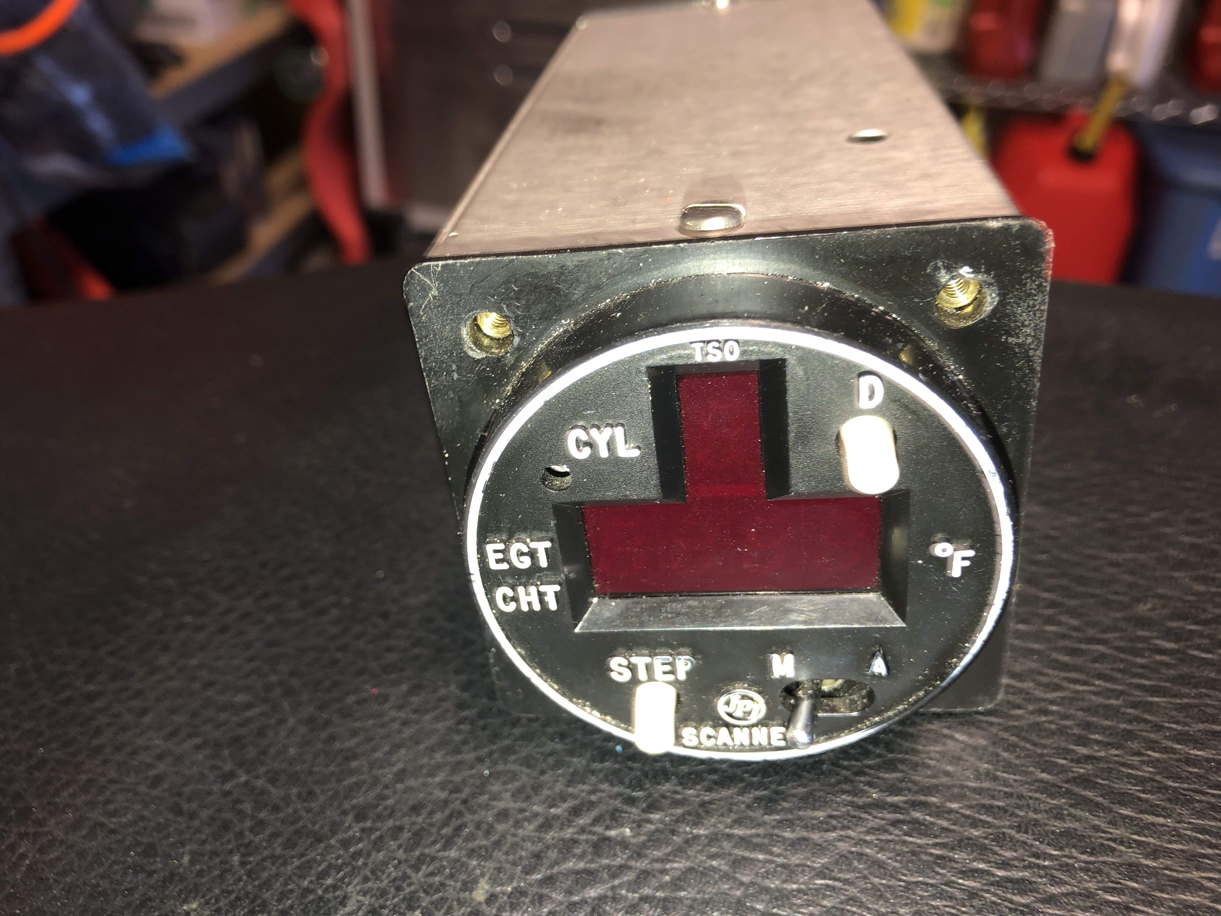
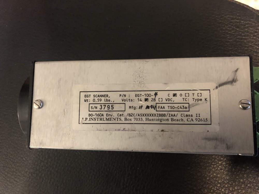
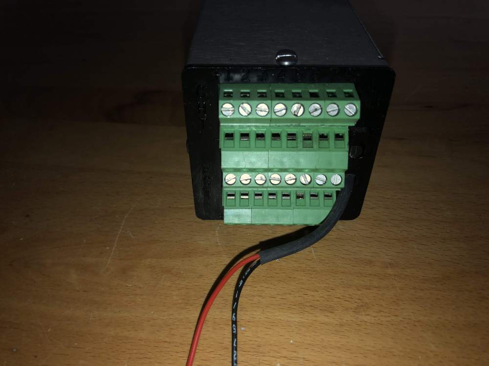
JPI Classic engine monitor working fine when removed. Large lighted digits for easy to read from most any angle. Screw type terminals instead of the hard to make DB09 connectors. Works with any K type thermocouples. $115 plus $12 shipping.

-
Do you have an old DME? It is higher frequency so it can’t be a harmonic but those things have been know to emit spurious RF. I had one in the past that would plot on my storm scope when tuned to a specific VOR. Make sure it is turned off when trouble shooting.
-
I have wished they would bring back the 2 inch gps/com like the gnc 300xl with wass. Forget the color graphics since anything smaller than a 750 is too small and most users are using their iPads for maps anyway. Just build in a good WiFi or blue tooth link to them that is non propierty. Garmin will never do this but an opening for Avidyne?
-
Draining tanks and fuel quantity calibration.
Gary0747 replied to Igor_U's topic in Vintage Mooneys (pre-J models)
We were talking about how much useable fuel is remaining after the float senders hit the lower stops, which should be the zero point of the gauge. CEIS appear to have 1.5 gallons below zero gauge reading. -
There are three ports on the servo. The inlet the outlet to the servo. And a tap from the body of the servo that goes to the fuel pressure gauge. I have gauges on both the inlet and the normal pressure tap..
-
Draining tanks and fuel quantity calibration.
Gary0747 replied to Igor_U's topic in Vintage Mooneys (pre-J models)
I wonder if the resistive senders read down to 1.5 gal useable also? -
Draining tanks and fuel quantity calibration.
Gary0747 replied to Igor_U's topic in Vintage Mooneys (pre-J models)
It appears to me that the floats will be resting on their bottom stops with a significant amount of fuel remaining some of which is probably useable fuel. I would think this should be the defining point for zero fuel on the gauges? -
I have an EI flow meter and pressure gauge between the engine mechanical pump and the servo and have just installed a JPI Pressure transducer at the location where the factory pressure gauge used to be. This is on the outlet side of the servo I assume. We will check the screen but have never found anything there since I assume the gascolator filter is doing a good job. The inlet pressure has been running close to 30psi and the outlet where the old factory gauge was shows 22 to 24 psi. I was reading the Precision Aeromotive manual for the servo and the only thing I could find about Pressure was a statement that “ In general inlet pressures 5 to 10 psi greater than engine requirements will not adversely affect the performance of the system”. Which makes me think the pressure drop I am seeing might be normal. The strange thing is I never noticed the difference on the old factory gauge but now do with the JPI.
-
Does anybody have any data or know what the Pressure difference between the inlet and outlet of the fuel servo on IO360? I am seeing about 6psi drop on different gauges.