

Gary0747
-
Posts
506 -
Joined
-
Last visited
Recent Profile Visitors
4,243 profile views


Gary0747's Achievements
")


-
I have been having a similar issue with my Johnson bar release button It seems harder to release as easily when compared to the 34 years I have owned and flown this plane. I have participated in nearly every annual in the past and the preloads have remained constant and never needed adjustment. The lock down block was replaced around 10 years ago and everything is well lubricated. With the bar out of the socket I can feel the tip of the release pin point that engages the Johnson bar. There is some slight burring or deformity of the point that engages the top of the Johnson bar. This may be entirely normal and the problem be elsewhere Has anybody noticed and dealt with anything similar?
-
Based on the G100UL fuel leak thread what's your position?
Gary0747 replied to gabez's topic in General Mooney Talk
I am late to this discussion but wanted to throw in a couple of comments I attended the presentation in Buckeye last year and asked the question about what testing had been done on our polysulfide fuel tank sealants. I just got a cursory answer that it was currently in an airplane fuel tank with no signs of leaks. I would like to see testing that might predict the long term effects on these sealants. Perhaps measuring surface hardness readings or adhesion force measurements both over exposure time. Any new fuel that replaces lead and straight chain hydrocarbons with aromatic hydrocarbons like toluene, benzene, xylene, etc to maintain octane will be more aggressive on paint and sealants and some types of rubber. The aromatics will typically increase the octane lost by removing the lead, but should have initially raised red warning flags in the development of this or any new fuel. I would have thought it critical to test the long term compatibility effects on day one of any new fuel development project like this. I think polyurethane paints and sealants will better resist aromatic chemical attack than acrylic paints and polysulfide sealants -
I have been closely monitoring the exhaust valves in my Lycoming IO 360A1A for a couple of years (which is only about the last 100 hours). I have 1400 hours on the engine and it is running fine. I am tracking the data closely on my JPI900. I have two exhaust valves that have the non symmetrical pizza pattern that are likely not rotating. There does not appear to be any signs of burning and they have had this distorted pattern for the whole time. Is there a way to get them rotating or should I just keep monitoring? I understand the Lycoming rotator caps are passive and only allow the valve to rotate if they want to so changing them may not do much?
-
How to seal most forward left panel aft of Cowling?
Gary0747 replied to Saira's topic in General Mooney Talk
I have the SWTA aircraft windshield smaller access panels with a simple solution that is reusable. Put a bead of RTV Silicone and cover it with Saran Wrap before installing the cover then trim the excess. -
Those cracks look pretty big but for smaller cracks, there are a few solvents that work well for bonding acrylic. Methylene Chloride, Ethylene Dichloride and Methyl Ethyl Keytone come to mind. One could put some in a a glass eye dropper and see if it will weep into the cracks.
-
Possible fuel pump failure or...?
Gary0747 replied to The Other Red Baron's topic in Vintage Mooneys (pre-J models)
Was it leaking fuel outside the engine? -
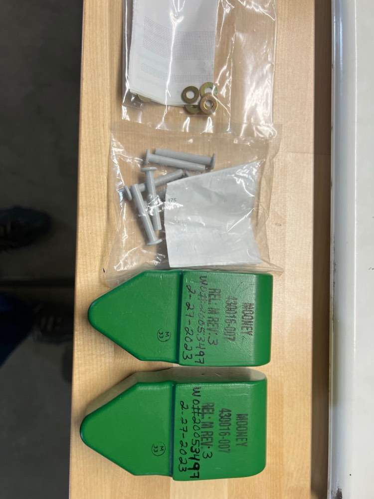
The new weights come right in spec with the service bulletin without filing so that worked perfect. The only issue I see is did the mechanic install rivets too short for the specific elevator he worked on. As mentioned above DMax has longer ones that can be cut to the proper length for a good set.
-
3.18 pounds. Both the same.
-
I must say Mooney did a nice job making these.
-
Apparently this QC check is called a “Conformity Check” and it is done by the FAA? I have never heard of this on previously manufactured and installed parts like this 40016-7 weight? If true we may have a longer wait given all the Continental AD stuff on the FAA plate now?
-
Anybody have info on the status of new weights from Mooney?
-
Yes that has bothered a lot me since I have been flying my M20F for over 30 years and well over 2,000 hours and some times near VNE with no sign of flutter. So why would I want to change the balance of the elevator by this large amount? I can only hope that there is more than one correct answer to the flutter prevention scenario. I do recall a post by a knowledgeable contributor (PT20J) in September that said the following which I hope is true: “Most control surfaces are overbalanced (i.e., leading edge heavy) to control flutter. With the control surface CG ahead of the hinge line, a deflection of the control surface causes a correcting hinge moment that tends to dampen out motions caused by aerodynamic forces. Evidently the Mooney control system is stiff enough that flutter is not an issue and so the control surfaces are underbalanced (i.e., trailing edge heavy) most likely for improving handling qualities. The Mooney ailerons have fairly heavy control forces due to their short span, wide chord design and the elevator forces are a bit high due to the springs and bobweights. Underbalancing would tend to reduce the initial hinge moment when a surface is deflected. But, that's just a guess; to know for certain the designer's intent you'd have to ask Al. “ Skip
-
The other thing that may cause the 540 M20Fs made prior to 1968 to require different balance setting is the bunges are different as well as the elevators. So if changing elevators pre 68 to post 68 is ever needed the bunges will likely need changing also.
-
There must have been a lot of -7 non hybrid weights used since there were only 130 sets of -1 hybrid weights. The remaining 410 M20Fs in the pre 1968 time period appeared to have the same balance criteria as the hybrid weights since no distinction is noted in the service manual. I wonder if the solid -7 elevators were actually balanced to the spec in the service manual? I see no way to get there with the current -7 weight a full pound heavier than the hybrid weight.
-
I measured my elevator when it came off and the weight was 1.60 pounds to 1.62 pounds. So now I am being told these numbers are not correct even though they are correct according to my service manual that applied to the first 540 M20F? The parts catalog only lists the -1 hybrid weight not the -7. So the question is which one was tested with the smooth elevators?

