
Shadrach
-
Posts
12,228 -
Joined
-
Last visited
-
Days Won
170
Content Type
Profiles
Forums
Blogs
Gallery
Downloads
Events
Store
Everything posted by Shadrach
-
A more correct statement would be that it’s hard to get an O470 to run smoothly with all cylinders LOP. It is not hard to get it to run smoothly with some cylinders LOP and some cylinders ROP. This engine was likely leaned at a high power setting and ended up with an uninstrumented cylinder operating at an abusive, ROP, mixture setting for an extended period of time. It heated up, then began detonating and self destructed. Any time a carbureted engine is leaned to rough and enriched to smooth (standard practice) there will likely be cylinders all over the mixture spectrum. That is why it’s a bad idea to lean a carbed engine above 65% power. It can be done with a well instrumented engine, doing so with a single cylinder CHT/EGT is asking for trouble.
-
I was think similar. It’s conceivable that even if the pump merely seized that the restriction would be less than with the impeller “windmilling” in the line.
-
https://aeromotors.azurewebsites.net/ Send an email (or call) Aeromotors. They may have a unit on the shelf that they can send out right away. The trouble is, you may need to wire funds as I don't think they take credit cards. Fuel pressure right at redline is not a concern for operations as Mooney's redline specification is much lower than the RSA fuel system redline (45psi IIRC). The question is what changed? Do you know where it usually runs with the mechanical pump alone? Mine is about 28psi using the engine driven pump alone; the boost pump pushes the needle to redline. You were smart not to fly. The boost pump is your only way of delivering fuel to the engine in the event of a mechanical pump failure. While mechanical pump failures are rare, a boost pump failure can on occasion induce other problems. There have been cases (rare) where internal pieces of boost pump parts have departed the pump housing and fouled the system up stream. If there is anything I can do stateside to help facilitate a pump for you, don't hesitate to PM me.
-
@AndreiC, what cylinder are you using as a reference for LOP cruise?
-
What are typical CHTs using book ROP power settings? You should enjoy lower CHTs at equal power when LOP. TIT may be a challenge to attaining the desired LOP power setting.
-
Indeed. Do understand that in order to be LOP at 16.5gph you will need to run higher MP than the book 75% ROP MP setting.
-
I never have figured out why the Owner’s manual says that. Every system that I have encountered is precisely 4 pumps IF the system is fully bled.
-
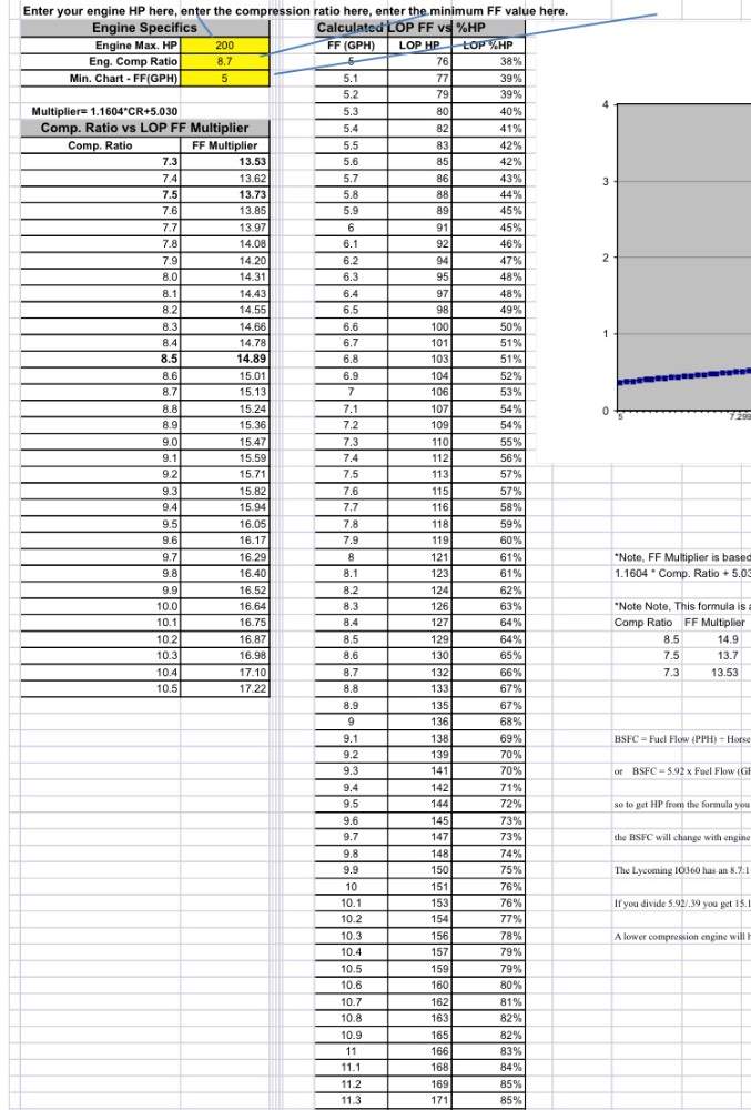
Your engine has a compression ratio of 7.5:1 which makes it less thermally efficient. For that reason, the multiplier/divisor is 13.7 instead of 14.9.
-
It’s not that simple. At Max FF of 33gph a significant portion of that fuel is going out the exhaust as unburned hydrocarbons. That surplus fuel is used to slow the combustion event. For your engine, 75% LOP fuel flow would be ~16.5gph. I cannot stress enough that a TSIO520 is a power plant that requires a thoughtful and conservative approach.
-
How many times do you want this verified? By how many people? Reread the thread and you will see a number of confirmations and the reasoning behind them. I'm not sure what else can be said. If you're really uncomfortable, maybe you should seek someone local that you trust or stick to the published POH power settings.
-
You are full of opinions about operations that you’ve never conducted and data that you’ve never seen
-
Is the actuator leaking or weeping? The vent hole at the bottom of the cylinder will weep a tiny amount of fluid over time. LASAR sells an overhaul kit for the actuator, but I’m sure the parts could be sourced locally. Several years ago I noticed a leak at the actuator. I took it apart but there was no evidence of a problem. I cleaned and reassembled everything and it’s been tight ever since. A piece of FOD must have entered the system.
-
Any idea what caused it? I’ve seen a number of detonation issues over the years. 0% of them were attributable to LOP operations.
-
Flaps should be totally hydrolocked after four pumps. More than that and there is air in the system. I made a short video so folks have a reference for how they should perform when properly set up.
-
It’s clear to me that it matters no number of factory power graphs, annotations, accompanying explanations and references will be sufficient to change your misperceptions and that is fine by me. No one has ever asked you to operate your plane outside of how you see fit. I just wish you would stop stating your opinions as facts (especially with no supporting data). When someone posts a question about engine operations they are typically looking for something more in-depth than, “you don’t need some fancy engine monitor to run LOP. Just run at less than 60% like me. I’m risk averse and you should be to because your engine will self destruct if you run more aggressively than I do and anyway there is no such thing as high power LOP and if there is you’ll shoot your eye out trying and…” How many pilots do you think have harmed their engines in the last several years incorrectly operating LOP?
-
The original calculations were APS numbers. Then someone created a CSV file that extrapolated multipliers for all compression ratios with an HP calculator (available here in the downloads section). Mathematically trying to differentiate between the the 14.89 used for 8.5:1 CR and the 15.13 used for our 8.7:1 CR Lycomings is like measuring two cubes of jello with a micrometer.
-
Without pictures it’s hard to tell. However, I would say that there are scenarios where an initial, high grit, wet sanding makes more sense than starting with polish. Yes it’s more aggressive but in my opinion it’s also easier to be methodical and consistent.
-
1) Remove the B-nut and plastic cover from the T shaped AN fitting on the ACTUATOR (lowest point in the system) and attach a pressure pot filled with the hydraulic fluid. 2) Ensure that the small lever is in the "flaps up" position (this is to say needle valve off the cam lobe that opens the check valve). 3) Attach an AN fitting with a 2' hose to the reservoir to act as an overflow. position the hose over a catch can (bucket). 4) Actuate the pressure pot and watch for fluid at the overflow hose at the front of the aircraft. 5) When you detect fluid coming through the overflow, cut the pressure from the the pressure pot. 6) Plug overflow hose and reservoir vent. 7) This is where it gets messy... remove pressure pot fitting and replace the blocking plate. 8) Remove whatever you used to block the reservoir vent plug (I've used chewing gum). Leave the overflow plug in place. 9) Select "down" position on flap lever and have someone simultaneously pump the the handle (slowly) while you back off the plastic plate on the aforementioned actuator "T fitting" just enough to allow it to leak. You should get fluid only, but possibly a small amount of air and then fluid. Have your pump person maintain gentle pressure. Make sure to only have the bottom of the system open under positive pressure from the pump person. Close it under pressure. If the person pulls up on the flap pump and the system is open it will draw air into the system... 10) With T fitting secure, pump the flaps down. Remove overflow hose, retract flaps and be ready with a rag to catch any overflow. If fluid level is too high in the reservoir , siphon a bit off with a drinking straw (use your thumb not your mouth). 11) close up the system, adjust flap retraction speed set screw so that the flaps take apprx 10 secs to retract, ops check, button everything up and go fly... The above process usually works. on occasion the pump cylinder will not draw in fluid. If that happens, it may be necessary to pre-prime the pump.
-
I’ve seen 15.XX used but we’re in “angels dancing on the head of a pin” territory. Friction losses are a consideration but one must also consider that the transfer of force (mechanical advantage) to the crank varies throughout the power stroke, and that those variations of pressure during the power stroke will differ with changes in RPM. 15 is a good round number that’s close enough. Operating above 75% LOP (FF above 10gph) is not dangerous. If one has an engine monitor, it’s very easy to demonstrate why, but you must be at low altitude on a cool, high pressure day . You simply set book manifold pressure and rpm for 75% power at 100 ROP, and wait to observe steady state CHT‘s. Then reset the mixture on the lean side at wide open throttle. What will be observed is that 75% on the lean side yields lower CHT’s. And indeed more than 75% also yields lower CHT’s all other things being equal. This is a repeatable observation. At 1500msl on a cold day I can fly as fast or faster on less fuel with lower CHTs on the lean side. It’s coming up on the time of year here in the mid Atlantic where flying at 4500MSL might equate to a DA of 1100 feet. Under those circumstances it makes good practical sense to set mixture for the highest power possible on the lean side. Especially if you’re traveling westbound and will have to deal with high winds at higher altitude. This gives the operator the ability to fly low while enjoying a fuel burn that mirrors high altitude ROP operations coupled with a high TAS that yields optimal GS by staying below the strongest winds. Unfortunately, mixture setting can’t improve the ride down low when it’s bumpy.
-
See my post above. If the numbers you posted are accurate, your engine was in a very happy and conservative place. Running closer to peak and pushing all of your CHT‘s into the low 300s would be equally efficient from a BSFC standpoint and slightly faster with no detriment to cylinder longevity.
-
Detonation is a function of peak internal cylinder pressure. Mixture affects internal cylinder pressure but suggesting that it’s the primary driver muddies the water. Ignition timing, temperature and piston speed, are all contributing factors. Precisely defining the “red box” in its entirety is not really possible for practical reasons. One would have to set subjective metrics on each side of the box and the edges would vary based on conditions. It is however, easy to define the center of the red box. It is the fuel/air ratio for a given RPM that produces the most rapidly propagating flame front which in turn produces the highest PEAK internal cylinder pressure and thereby the highest CHT. Typically ~40ROP. Small changes in mixture from that point either richer or leaner make only small differences in flame front propagation and peak ICP. At some point beyond those small changes, propagation and peak pressure start to decrease significantly (relatively speaking). At some from peak ICP, going leaner generates a somewhat more rapid decrease than the corresponding point on the rich side. The Lycoming graph I posted earlier presents a clear, conceptual picture of the spectrum. The center of the red box (highest peak pressure) is depicted in the graph as the top of the CHT curve (hottest point). From an internal cylinder pressure standpoint, at any manifold pressure, peak EGT or leaner is more conservative than 100° ROP. By ~50° LOP, The engine is getting to a place that’s more conservative than 250° ROP. However, it’s difficult to make direct comparisons. CHT (all other things being equal ) is more a function of peak ICP than mean ICP. Power is a function of MEAN pressure produced during the power stroke. The slower nature of LOP flame front propagation can produce equal (or higher) mean pressures with lower peak pressure. Sort of the difference between a hammer blow at the top of the power stroke (ROP) and a constant push (LOP). EDIT: Hat tip to @bluehighwayflyer for catching a ROP/LOP typo. Correction made.
-
CHTs in the high 200s/low 300s at an OAT of 40° are not “Redbox” numbers. It’s prudent to pay attention to the actual feedback from the engine, rather than generalized, one size fits all, theoretical recommendations. Here’s a controversial statement based on decades of operating a normally aspirated IO360 - The “Redbox“ does not extend into the lean side of the mixture spectrum for a Lycoming IO360. Its borders, while fuzzy, are located solely on the rich side of peak EGT.
-
Looks like I got burned by the interwebs. Before posting, I did an image search of the TSIO360-MB1 and this turned up. My mistake.

-
I’m not saying it’s impossible, but highly unlikely to get an approval to move to a new category. And if you were able to it would likely be for flight testing purposes only so no passengers or travel.
-
That is a conservative setting (just under 70%). If your CHTs are only 240° Higher than the OAT of 40°, your engine is not stressed.