1980Mooney
-
Posts
3,441 -
Joined
-
Last visited
-
Days Won
7
Content Type
Profiles
Forums
Blogs
Gallery
Downloads
Events
Store
Everything posted by 1980Mooney
-
201 Gear Up at KDWH
1980Mooney replied to Mooney in Oz's topic in Mooney Safety & Accident Discussion
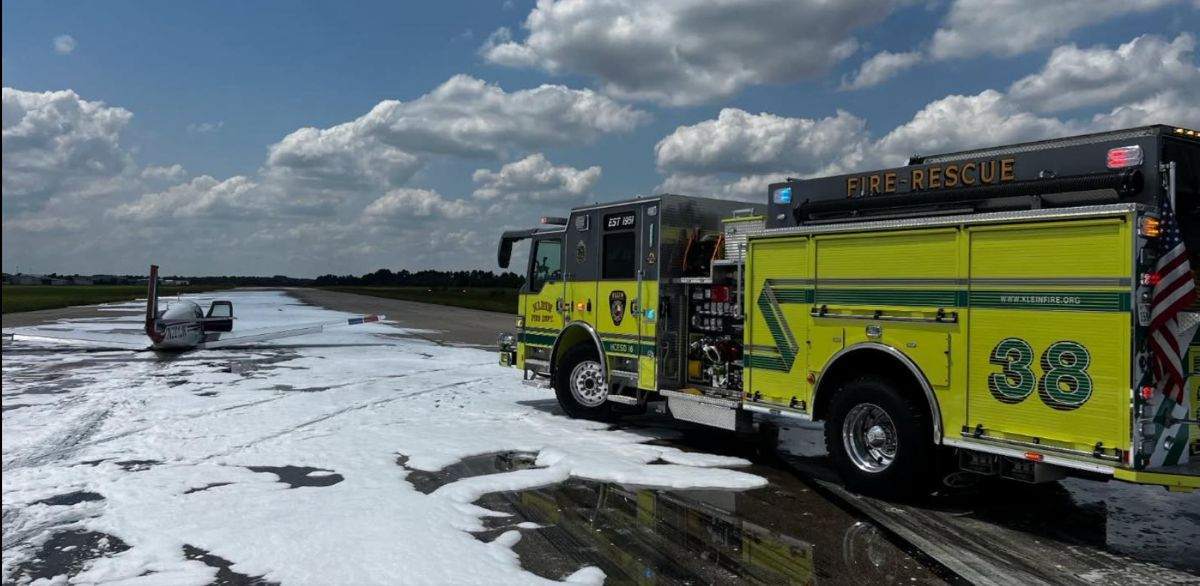
Here is pic of them in action spraying the foam. They must have sprayed 1,000 gallons easy - maybe 2,000. Maybe more....
-
201 Gear Up at KDWH
1980Mooney replied to Mooney in Oz's topic in Mooney Safety & Accident Discussion
Per Channel 11 "Firefighters from multiple agencies responded, including Klein Fire, Spring Fire, Champions Fire and Northwest Volunteer Fire." and "Crews used Klein Fire’s Foam 30 unit to lay down a foam blanket on the runway" It appears that Klein Foam 30 carries Class A and Class B foam. The Class B foam (AFFF) is what they say that they use for flammable liquid fires. The news reported that the pilot flew longer "to burn off excess fuel" so someone was overly concerned that a gear-up Mooney landing might start a fire. (never heard of it happening to a Mooney unless the plane departed runway and struck an immovable object/antenna/etc) Class B foam (the bad stuff with "forever fluorocarbons" costs about $30/gallon. The non-fluorocarbon Class B costs about $200-300/gallon. It appears that they put down a crapload of foam. I bet there is a similar amount behind the plane. 300 gallons?..500?...1,000? 300 gallons is less than 6 drums. I bet it is more. Who is paying for that? Since insurance is involved, I wonder if the Klein fire department tries to bill it to the Mooney owner. There is no way that the airport will pay for it. Hooks is privately owned by the Gill family. Hooks is one of the airports that charges ramp fees which are so despised on MS.
-
Was the Inogen G5 set to flow rate #6 (highest) during all test altitudes?
-
Mooney Aircraft Accident Nampa, ID
1980Mooney replied to 65MooneyPilot's topic in Mooney Safety & Accident Discussion
There doesn't appear to be a stiffener. It just appears to be a bracket welded to the tubular. Only a bracket is shown in the parts diagram - no separate stiffener is shown. Here is a J pilot seat shoulder attachment point. Here is a Long Body which would show any later model change. The Pilot and back seat shoulder harness attachment points are shown. You can see the simple bracket. And here is the parts diagram for the S and R. Only a bracket is shown - #63 Copilot and #71 Pilot shoulder harness attachment point. The Acclaim parts manual shows the same. Interestingly they don't even show the back seat shoulder harness welded on brackets; however, they clearly exist in the picture of the Long Body frame.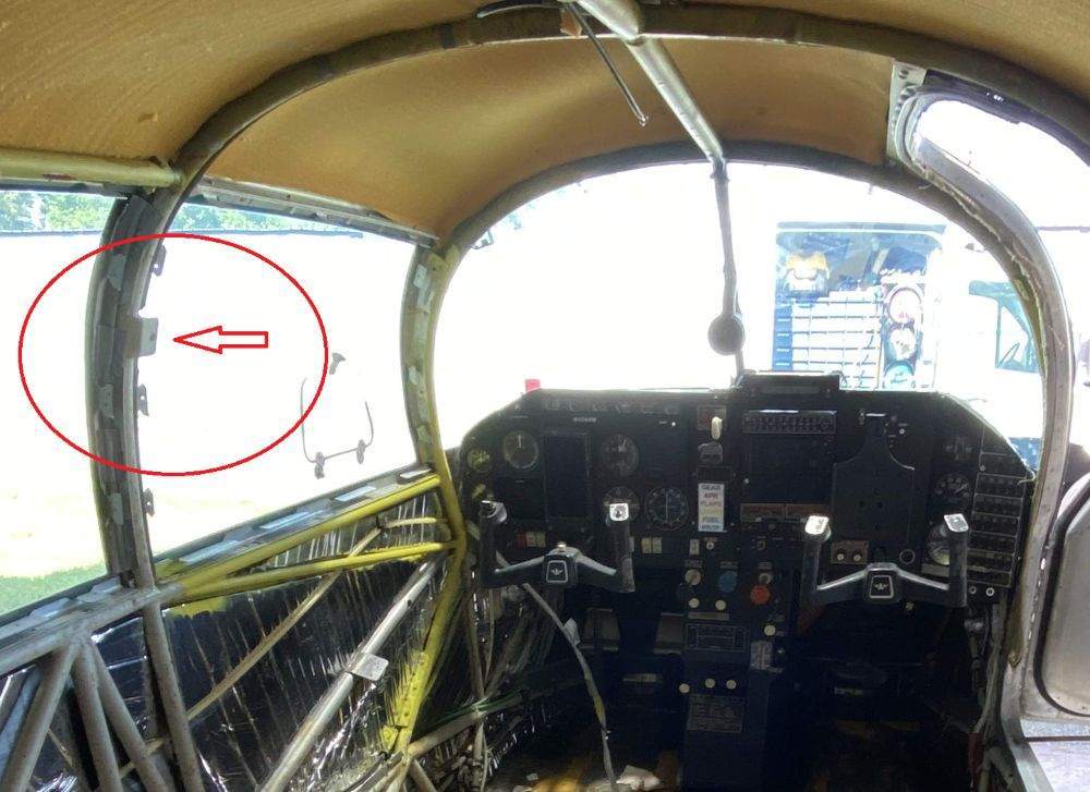


-
M20F Gear Up at KMJX
1980Mooney replied to Mooney in Oz's topic in Mooney Safety & Accident Discussion
It appears based on the time stamps at (KMJX) Ocean County Airport, NJ, that Mooney N211CT , a 1966 M20F, did one " full stop, quick taxi back and go" (it took about 5:25 min:sec to clear the fence on short final and then clear the other fence on take off), then one "touch and go",(it took only about 1:31 min:sec to clear the fence on short final and then clear the other fence on take off) and then another " full stop, quick taxi back and go". The runway 06 is 5,950 ft long. Then on the 4th landing he landed gear-up. https://globe.adsbexchange.com/?icao=a1bd7d&lat=39.927&lon=-74.314&zoom=14.2&showTrace=2025-08-05&trackLabels×tamp=1754407409 Although this M20F was stripped and heavily modified by Mooney Mart back in 1998 with all the "201" speed mods and 201 style panel, it has a Johnson bar. N211CT | 1966 MOONEY M20F on Aircraft.com "Johnson Bar Gear Control, 201 Instrument Panel, 201 Glare Shield, 201 ¼ inch Windshield, ¼ inch Side Glass Mod with, 201 Picture Windows, 211 Speed Kit (gap seals all around & gear door overlap), Wing Wheel Well Liner Fairings, Electric Speed Brakes, “Whisper” Super Sound Proofing New Paint 1998, New Leather Interior 1998"

-
Continental IO-550G (5) Engine Driven Fuel Pump
1980Mooney replied to Greg_D's topic in Modern Mooney Discussion
https://consolidatedfuelsystems.com/continental-fuel-pumps/ Great Planes Fuel Metering has been the go to shop in the past for Continental pump overhauls. Last year Private Equity Victor Sierra acquired them. ( Vance Street Capital is behind it -They own McFarlane and Tempest, etc and balled it all into “Victor Sierra Aviation Holdings”). Probably still good but with higher prices… Consolidated Fuel Systems™ Acquires Great Planes Fuel Metering https://consolidatedfuelsystems.com/wp-content/uploads/2024/03/Great-Planes.pdf -
That makes the most sense. Use the old plastic one as a template. It will never crack again….
-
Seatbelt (Re-webbing): Who have you used/What to look for
1980Mooney replied to Paul Thomas's topic in General Mooney Talk
Davis Aircraft Products, Bohemia, NY, supplied most of the seat belts to Mooney during the 70's-80's.. My 1980 J had the original worn seat belts with Davis Aircraft tags. Davis Aircraft Products, is still in business and will reweb/repair your belts. You can reuse your hardware if it is in good shape. I sent mine there a few years back. General Aviation Aircraft Seat Belts | Davis Aircraft Company Davis Aircraft Products Co, Inc. 1150 Walnut Ave Bohemia, NY, 11716 Phone 631-563-1500 Davis Restraint Systems, Inc. 184 Wire Drive Andrews, SC 29510 Phone 843-264-2500 BTW - about 10 years ago there was a FAA enforcement action against a number of mom and pop rewebbers that were resewing/rewebbing belts at a discount to the certified shops. They were shut down and planes found with those belts during ramp checks were grounded, The FAA inspector came into the maintenace shop at my home field and inspected the belts of planes being worked on. There was a Cessna 421 in the shop that had new belts from one of the offending belt shops (here was one on the Gulf Coast that was popular but I can't recall the name). It was grounded and could not fly out until all 10 sets of seat belts were replaced. I got this straight from the shop owner. There were some posts/articles at the time but I cannot find them now. Although you may never be ramp checked, think about resale of your plane if you opt for a "lower cost" seat belt repair without certification. -
Mooney Aircraft Accident Nampa, ID
1980Mooney replied to 65MooneyPilot's topic in Mooney Safety & Accident Discussion
You are absolutely correct, -
Can we put a limit of new posts per 24 hours in this forum?
1980Mooney replied to AndreiC's topic in General Mooney Talk
Can we put a limit of new posts per 24 hours in this forum? Also there is the Law of Unintended Consequences..... If you limit the number of new posts per day, then no legitimate MS member will ever be able to post anything. The AI/BOTS (that never sleep) will choke up the quota before any human can post any new topic in any 24 hour period. -
Can we put a limit of new posts per 24 hours in this forum?
1980Mooney replied to AndreiC's topic in General Mooney Talk
Thanks for the time that you spend on this site. -
Is that how you keep the crap out of LancairLive?
-
Seriously how many new members can there be? KISS. Keep it simple stupid
-
Why not freeze current members, delete all the offending automated members and any new members are vetted through a manual process?
-
Beechtalk has 35,000 members. At least 10 times more than MooneySpace. Explain why it’s practical for them but not us.
-
Ask Beechtalk. They don’t have a paywall and they don’t have this problem.
-
Seeking Advice - Sell OR Keep N9353M?
1980Mooney replied to Zippy_Bird's topic in General Mooney Talk
A lot of drift here. Not sure what it has to do with the OP’s topic….. I thought my finger slipped into the Avionics/Panel Discussion section. -
Mooney Aircraft Accident Nampa, ID
1980Mooney replied to 65MooneyPilot's topic in Mooney Safety & Accident Discussion
I have a hard time believing that. 2,500 ft, badly leaned or not, gear down or up, flaps takeoff, full or not, a Mooney with 2 adults on board will climb. Ham fisted Mooney owners take off all the time, poorly leaned - and I wager many at 5,000 DA. If Mooney's were that sensitive they would be falling out of the sky every day in the mountain west, especially in the summer. They would be labeled a "death trap". As they say "It just ain't so".... -
Mooney Aircraft Accident Nampa, ID
1980Mooney replied to 65MooneyPilot's topic in Mooney Safety & Accident Discussion
Agreed. 2,500 ft elevation and 5,000 ft DA should not be a problem. I would fly my J (pre Missile conversion) out of Albuquerque at 5,355 ft elevation all the time - many times at max gross with seats filled. It has a long runways but still a non event. Same with Santa Fe. You just focus on a nice steady climb. -
Mooney Aircraft Accident Nampa, ID
1980Mooney replied to 65MooneyPilot's topic in Mooney Safety & Accident Discussion
Per Adam’s Report- no wind Weather: METAR KMAN 272335Z AUTO 00000KT 9SM CLR 32/11 A2993 RMK A01 METAR KMAN 272355Z AUTO 00000KT 9SM CLR 32/11 A2993 RMK A01 -
When there is no Basic Med required, no third part scrutiny, no reason to do a structured self evaluation/assessment, it becomes easy to convince oneself that "I am good enough to fly" in spite of the facts. I suspect that there are many Mooney families here that have "taken the keys away from Grandpa" even though he was convinced in his mind that he was still able to drive a car safely. It's a slippery slope....
-
Mooney Aircraft Accident Nampa, ID
1980Mooney replied to 65MooneyPilot's topic in Mooney Safety & Accident Discussion
Looks like "Kathryn's Report" as become "Adam's Report" Interesting Adam's Report: Mooney M20J, N5764H, fatal accident occurred on July 27, 2025, near Nampa Municipal Airport (MAN/KMAN), Nampa, Idaho -
I think I hit a nerve. I must be on to something. It's a slippery slope.....
-
Mooney Aircraft Accident Nampa, ID
1980Mooney replied to 65MooneyPilot's topic in Mooney Safety & Accident Discussion
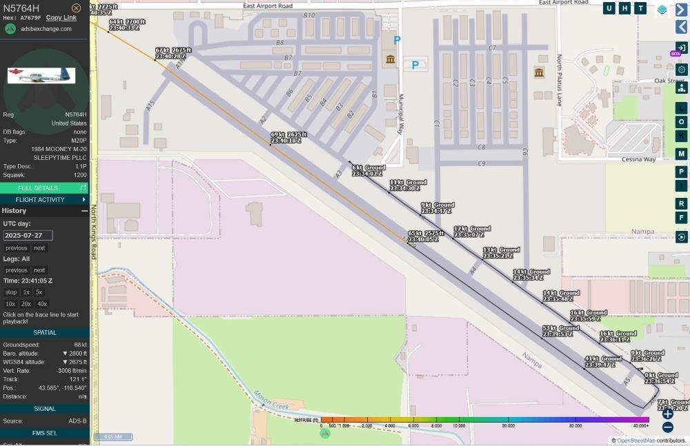
True. Lack of experience could cause indecision until it is too late. With enough experience in one's own plane - you may sense something is not right - feel, sound, response. Elevation at Nampa is 2,537 ft. Temp was 88 F at the time. I don't know the baro. This was a 5,000 ft runway. Still plenty of runway to take off or put it down if not right. And looking at the map and charts there appears to be about an additional 600 ft overrun before hitting the perimeter fence. Hindsight is perfect. The same thing killed McSpadden. -
Mooney Aircraft Accident Nampa, ID
1980Mooney replied to 65MooneyPilot's topic in Mooney Safety & Accident Discussion
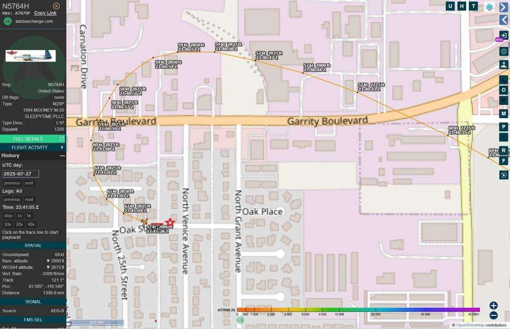
Very sad indeed. The LLC owner is a 43 year old in Eagle, Idaho. He got his Private on 6/28/2024. He purchased the 1984 M20J fairly recently - it was registered in his LLC on February 28, 2024 when he lived in Fresno, CA. The Mooney, which was sold in Florida, arrived in Fresno on April 2, 2024. https://globe.adsbexchange.com/?icao=a7679f&lat=34.836&lon=-118.303&zoom=7.4&showTrace=2024-04-02&trackLabels×tamp=1753659666 This appears to be the ad at the time of sale N5764H | 1984 MOONEY M20J 201 on Aircraft.com On August 5, 2024 he relocated it to Nampa, Idaho https://globe.adsbexchange.com/?icao=a7679f&lat=40.863&lon=-118.532&zoom=7.2&showTrace=2024-08-05&trackLabels×tamp=1753659666 The family has posted that the pilot, his wife and young child perished in the crash. Woman originally from Kingsburg killed in Idaho plane crash with husband and baby The Coroner reports that the boy was 23 months old. Coroner IDs 23-month-old boy as Idaho plane crash victim | Idaho Statesman The Mooney never got above 69 knots on the 5,000 ft. runway at Nampa. He got to about 325 ft AGL in the turn back before stalling. https://globe.adsbexchange.com/?icao=a7679f&lat=43.586&lon=-116.538&zoom=17.7&showTrace=2025-07-27&trackLabels×tamp=1753659661 Tragic. Something to think about every time you take off with your family. I didn't used to think about it much when the family was young. Now, older and family grown, I think about a lot more. Flying is not as fun as it used to be.