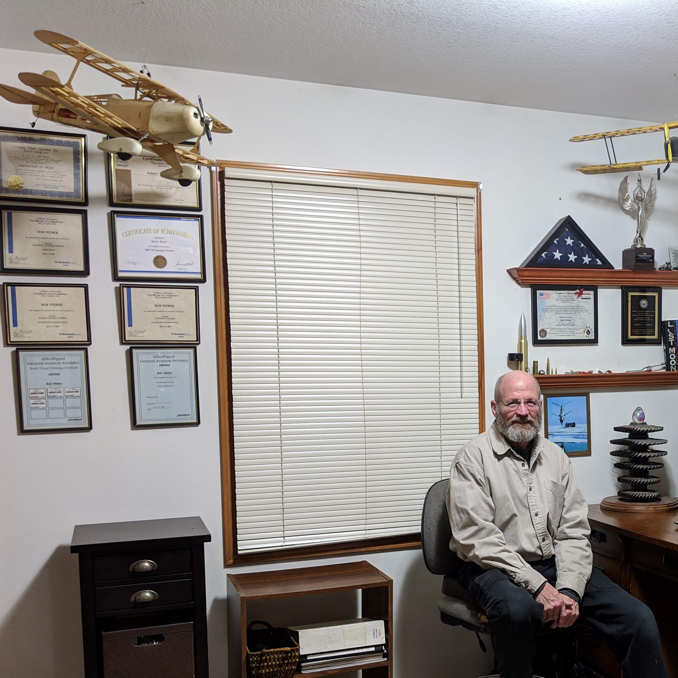
Bob Weber
-
Posts
185 -
Joined
-
Last visited
1 Follower

Bob Weber's Achievements
")


-
KFC200 - KC290 mode controller holes
Bob Weber replied to milotron's topic in Avionics/Panel Discussion
Another perspective.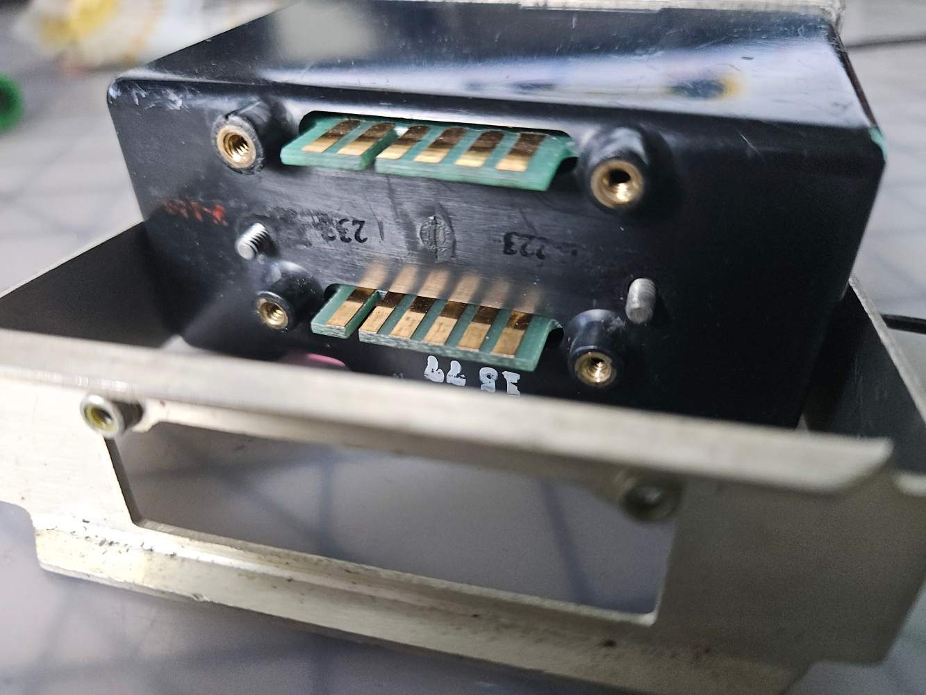
-
Regretfully Eric, I hear that story all too often. I wish I could have met you when you started down that road, I have assisted many with the same issues to success. Troubleshooting is an art in its self, troubleshooting autopilots is a challenge without a lot of experience and training on them
-
Warren emailed me, I will return with a call. Eric I can help you get yours back up and running if you would like, contact me at 616 822 1999 9am-5pm Eastern.
-
NAV and APR modes use Course Datum and CDI to navigate the " Raw Data" like we were taught in training. The course select is like a heading bug to set the intercept of a course. Once established on course with centered CDI, the course is allowed to drift slowly for wind correction. I like the GI 275's and your KAP 150 will love them when correctly installed and set up.
-
Thanks for the response, we found one. The servo will be shipped half way around the world to a guy in the middle of circumnavigating it!
-
Anyone removing a Century 2000 autopilot from an M20K? We're looking for a pitch servo to replace a bad one.
-
Another KFC 200 Autopilot Issue (won't level out)
Bob Weber replied to natdm's topic in Avionics/Panel Discussion
That could be a slipping clutch. -
New GI275 install; problem with KAP150 integration
Bob Weber replied to Alangj's topic in Avionics/Panel Discussion
I have a fresh tagged by Bevan Aviation KC 192 -03 with rack. -
New GI275 install; problem with KAP150 integration
Bob Weber replied to Alangj's topic in Avionics/Panel Discussion
The GI 275 most certainly was designed specifically for interface with many legacy Autopilots, when properly aligned they shine! I can assist your shop in troubleshooting this, Have them give me a call and I can point them in the right direction. 616 822 1999 mon-fri 9am-5pm Eastern. This should be simple to correct, the GI 275 is a wonderful upgrade from the KI 256 and this is certainly not the first attempt at interfacing one to a KC 19(x) computer.. -
S-TEC 55x software / hardware mod for integration with G1000
Bob Weber replied to dvk's topic in Avionics/Panel Discussion
I've got you covered, just sent you an email. -
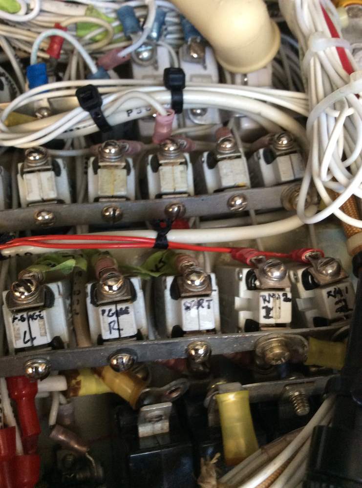
The biggest killer of breakers is a loose connection in my experience. I recommend checking all the screws for tight, anytime you find yourself in that area. My all time winner so far, a breaker switch feeding an avionics master buss in a 340A. The "Australian Hall of Flame", a foot of the 10 gauge wire feeding it needed replaced as well. His trim system worked better than he ever remembered after the repairs.
-
King autopilot roll servo removal
Bob Weber replied to mooneyflyfast's topic in Avionics/Panel Discussion
I would be very interested in what "other stuff" was pulled. That is a rather complicated installation and should have been 2 bolts on the mount and a Winchester connector. I would be happy to give advice to make sure that thing goes back in just right, I have the installation manual that will be needed, especially if the cable and mount are loose. webairconsulting.com -
King autopilot roll servo removal
Bob Weber replied to mooneyflyfast's topic in Avionics/Panel Discussion
Jake will treat you fair and very thorough, I was going to recommend him. -
King autopilot roll servo removal
Bob Weber replied to mooneyflyfast's topic in Avionics/Panel Discussion
I can assist here, it isn't too difficult. where are you sending it and what is the failure? Bob Weber webairconsulting.com -
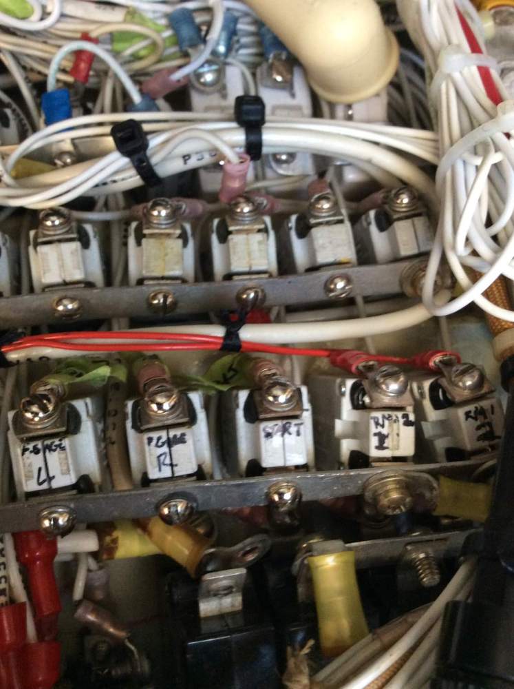
https://webairconsulting.com/ You are welcome I assist folks all over the planet troubleshooting the old systems I spent 40+ years installing and repairing. Quite often my guidance can navigate you thru the diagnostics without swinging a prop! My record time was 15 minutes, a guy with a Cessna 340A, flying in the soup routinely, in Queensland Australia with his family aboard. We spoke for 5 minutes ground checking the system looking for a trim issue in his 400B IFCS system. He hesitated after I had him turn on the Avionics Master, saying "it does this sometimes". I could hear him flipping the switch several times before he said OK what's next? When I asked him about what just happened, he said the radios won't come on without flipping the switch like I heard. I answered his question by requesting he put an out of service tag on the aircraft and send me a picture of it. in minutes I got the pics from 9,000 miles away. Where's waldo? He said it was doing this for years and getting worse...