
JimK
-
Posts
35 -
Joined
-
Last visited
Content Type
Profiles
Forums
Blogs
Gallery
Downloads
Events
Store
Everything posted by JimK
-
Someone said that the silicone gaskets sometimes leak and other times they don’t. I have found that the key is cleanliness. I have even reused them and they work fine. Make sure the mating surfaces on the valve cover and head plus both surfaces of the gasket are completely free of oil film and then install dry and torque to 20 in-lbs (retorque during every annual). if you get a leak or one develops later, don’t just retorque because that very slippery gasket sitting on an oil film just promotes gasket migration and leaks. Disassemble, clean all surfaces and reassemble. You’ll be happy with the results.
-
Yes, I’m sure he has replaced his battery by now but hundreds of other Ovation owners may benefit from knowing they can’t substitute a Gill battery for a Concord.
-
The elevator horns on my Ovation looked like Slick Nick’s at cruise when I bought the airplane 5 years ago accept they were even higher (approximately 8 degrees above the horizontal stab surface). I also thought that seemed wrong so I called Mooney and they connected me with a very sharp and experienced customer service engineer. He said that having the horns high on an Ovation (and likely other models) is normal but said Mooney tries to adjust the trim tabs on the aft edge of the elevators so the elevators are at least 2 degrees high. He said it wouldn’t hurt anything if mine were higher than that but, if it bothered me I could very carefully bend the trim tabs an extremely small amount to make the elevator more closely align with the horizontal stab but not to go too far because they should always stick up at least 2 degrees in order to be aerodynamically stable.
-
Best way to affix new wing fuel sight guage
JimK replied to Chris K's topic in Modern Mooney Discussion
After RTVing my replacement site guage into the hole as people have described, I allowed the RTV to cure, then I cleaned the area with alcohol and then cut a 3” circle of automotive Paint Protective Film (PPF) and installed it centered over the guage. Whether the RTV fails or not, that guage is not coming out in flight any more. Guaranteed! -
My 2008 Ovation doesn’t have and overflow/vent tube exiting the bottom of the fuselage. Therefore, I only have the Concord sealed battery choice and I suspect you have the same configuration.
-
On my last 1994 MSE I completely refurbished the plastic interior parts. Removed all panels, fiberglassed the back side of all cracks, filled front side discrepancies and painted all of them using SEM products sprayed with a small HVLP gun. I reinstalled them using new stainless hardware and they looked absolutely brand new. SEM makes one type of paint for the plastic and a different type for the upholstered parts. You get a very, very durable finish and whatever colors you want. It’s a lot of work but it can certainly be done DIY for very little money.
-
Looks like you have good offers of replacement senders so I’d like to ask A question. Rgpilot, I see you also have an Ovation. Did you replace your senders with Ceis senders just because you wanted them or were you having sender problems. If having problems will you share with us specifically what those problems were? Thanks!
-
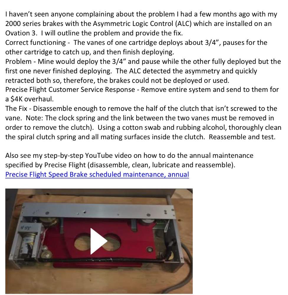
If your speed brakes are not operating you might watch this video to see if they can be easily fixed without the $4K overhaul that Precise Flight offers.
-
Jetpilot86, if you have stripped/noticably worn gears it sounds like your speed brakes were not getting the annual clean & lubrication that Precise Flight recommends (most people don't even know about this recommendation so I'm guessing you are not alone in this malfunction. I have a YouTube video which shows how to do this annual maintenance. The actual time between lubrication depends upon how much your airplane sits outside and how much it's flow but annually is likely a minimum time between lubrications. Also, I just posted a new YouTube video https://youtu.be/FxgaaQekxnE which shows how to fix your speed brakes at the same time you are lubricating them provided the malfunction you are experiencing is caused by a slipping clutch. FYI - Many times a slipping clutch is not immediately apparent but is likely the problem if the speed brakes do not deploy correctly or are erratic in their deployment.
-
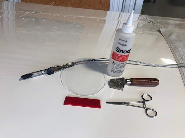
Here is how I find and fix fuel tank leaks: Step 1, Clean up – Completely drain all fuel from the tank by removing the drain valve on the inboard lower surface of the wing. Once all fuel is drained, leave the fuel cap and drain valve open overnight to evaporate all explosive fuel vapors. Remove the appropriate access covers and interior panels (Not the fuel tank covers yet) to gain access to the all outside surfaces of the tank. Note: You can delete interior panel removal if there is no fuel smell inside the cockpit. Using an effective solvent like MEK, do a really good job of cleaning all blue fuel stains off of the outer surfaces of the tank. Step 2, Find leaks on the outside – Reinstall drain valve and turn fuel selector valve to OFF. Connect a very low pressure gage to the fuel vent. Devise a plug for the fuel filler neck that will connect to the exhaust side of a shop vac or some other very low pressure, accurately controlled supply and pressurize the tank. WARNING: DO NOT APPLY MORE THAN 1.0 PSI PRESSURE TO THE TANK BECAUSE HIGHER PRESSURE COULD SERIOUSLY DAMAGE THE WING STRUCTURE! With pressure applied, brush Snoop leak detection fluid over all exterior seams/joints/fasteners and mark everywhere that bubbles form until you have marked all of the leaks coming from the outside of the tank. Note: This step is only to get a general idea of where the leaks are in order to know which fuel tank access covers need to be removed. Step 3, Remove inspection covers – Use directions I have provided in a Mooney Space post to remove the appropriate fuel tank inspection cover(s). Step 4, Find leaks on the inside – Plug the fuel tank vent and position the fuel selector to off. Fabricate a clear plastic panel (.060 is sufficient thickness) large enough to cover one inspection cover opening. Mount a vacuum gage in this cover to indicate the vacuum level in the tank (do not seal this cover to the fuel tank opening because you need to be able to quickly remove it periodically and the vacuum will keep it in place anyway). Connect a shop vac hose to the fuel filler neck. Brush Snoop or other leak detection fluid on a small joint/fastener row and quickly place cover over the wing opening and turn on the vacuum source. DO NOT APPLY MORE THAN 1.0 PSI VACUUM TO THE TANK BECAUSE HIGHER VACUUM COULD SERIOUSLY DAMAGE THE WING STRUCTURE! Either a bright light inside the tank before placing the plastic panel or a light shined through the plastic panel will allow you to see bubbles at the leak. Again, mark all the leaks on the inside of the tank. Step 5, Repair the leaks from the inside – Under the supervision of an A&P mechanic and using the procedure and materials specified in the Maintenance Manual section 28-11 & 28-12, repair the fuel tank leaks. Step 6, Reinstall inspection covers – Use directions I have provided in a Mooney Space post to reinstall the fuel tank inspection covers. Please see attached photos of the special tools I made to do this job.


-
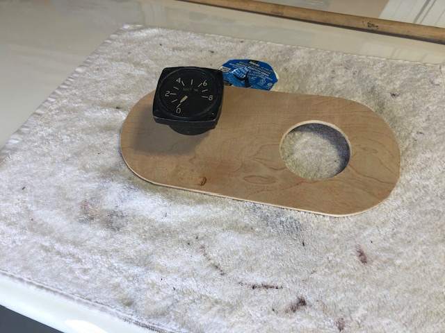
Here is how it worked best for me on my Ovation 3 to remove an upper fuel tank inspection cover which had never been removed before: Step 1, Fastener Removal Prep – I used a #10 paint cutter 12-02456 from Aircraft Spruce to cut the paint around all fasteners in the cover. Then I used a sharp pick to completely clean out the paint from the Phillips recesses in the screws being very careful to push down instead of prying up on the paint. This resulted in clean removal of all screws with no chipped paint on screw heads or the wing skin and no stripped out Phillips heads which, fortunately, resulted in no need to drill out the fasteners. Step 2, Cover Removal Prep – Using an Exacto or razor blade knife, cut the sealant/paint between the wing skin and the cover. It works best to use a very bright light to illuminate the mating edges of the skin & cover to ensure you are cutting in the correct place. Run the knife very carefully along the edge of the wing skin opening, not along the milled edge of the cover (brace your knife hand solidly on the wing to keep the knife from getting away from you which would result in a deep scratch in the wing skin). It may take a couple of passes to cut all the way through the sealant. When the knife has penetrated all the way through the sealant you will feel the knife bottoming on the aluminum cover. Step 3, Cover Removal – Pinerunner recommended installation of screws (I used #10X1/2 button head) in the three holes on each end of the cover and then put heavy weights on them overnight. That method is the very best way to remove the upper covers. There is no paint damage, no cover damage and very little work. Just leave the fasteners ¼” or less above the wing surface (it is critical to have all of them the same height above the skin in order for them to share the weight load equally), place a piece of plywood or 2X4 centered on the cover, then place enough weights (I used barbells but any compact, heavy weights would work) on top of the wood to result in at least 20# per fastener (20#/fastener X 6 fasteners is 120#). If the cover sealant doesn’t break loose within minutes, leave it overnight or longer and/or double the weight. One end of the cover will eventually break loose then remove the weights, move the screws to the next locations that you want to break loose and place the wood and weights on it again. It goes pretty fast after the first end of the cover breaks loose. Step 4, Cover Reinstallation Prep – Clean up the cover and wing skin mating surfaces using a bright light, inspection mirror and a short, sharp plastic scraper to remove the thicker areas and MEK solvent to remove the remaining thinner areas of sealant. Be sure to also remove the sealant from the countersinks on the cover and dimples on the skin so that new sealant can be applied to these areas during reassembly. Step 5, Cover installation – When ready to reassemble, use the screws that were removed (they already have perfectly painted heads). Be sure to use the Maintenance Manual recommended red cover sealant or else this removal method will not work the next time the cover has to be removed. Torque all screws in sequence around the panel (30 in# should be sufficient), allow the sealant to squeeze out and retorque. Perhaps repeat this retorquing a couple of times a few minutes apart. Wipe off excess sealant squeeze-out with MEK. Step 6, Finishing – Clean all surfaces to be touched up using MEK. Mix the Acry Glo color for your airplane. Use a sharp toothpick or a very, very tiny artist brush to fill the grooves left by the paint cutter around each fastener head (overfill a little bit because the paint will shrink while curing). Do the same with the groove left by the Exacto knife around the cover. You may also want to dab a bit of paint in the Phillips recesses of the fastener heads to make them match the screws in the undisturbed covers. Allow the paint to cure. Apply a second coat if the paint touchup shrinks more than anticipated. Once cured, wet sand only the touched up areas using 600 grit sandpaper wrapped around a small wooden block until any high spots in the touchup paint are knocked down. Then, using the same block wrapped with 2000 grit paper, finish sand the same areas. Then polish out the sanding scratches either manually or with a power buffer using fine polishing compound. You should now have a cover that looks almost like the original factory installation (see attached Before & After photos.
-
Troubleshooting Fuel Indication Issue
JimK replied to Slick Nick's topic in Modern Mooney Discussion
I recently had a similar problem with my LH fuel guage. I too suspected the inboard sender and spent a lot of wasted time troubleshooting it to no avail. The inbd and outbid senders on a specific tank are wired in series so either sender malfunctioning will screw up the indication for that tank. I recommend you remove the outbd one first because it is so much easier to access and you don’t have to drain near as much a gas to do it. Bench test it with an ohm meter. It should smoothly register changes from zero to 30 ohms as you move the float from one end of the travel to the other. If there are any dead spots, jumps or hesitations in the readings, send it off to Air Parts of Lock Haven. For $220 they will overhaul it for you and, for another $7 they will include a new gasket (much cheaper than Laser). If it’s not the outbd sender you will have to remove the inbd one first because and do he same test. -
Someone please correct me if I’m wrong but I think his thread confuses the 310hp STC with O3. They are not equivalent. You can add the STC to any Ovation but it is much more extensive to fully convert an older model to an O3. A O3 is a model that rolled out of the Kerrville factory with 310hp but it also has the O3 paint job with O3 badges, some interior improvements like the improved fwd cup holders etc and the GFC700 autopilot which is built into the G1000. The GFC700 autopilot alone is a huge difference. Much better than all the previous APs.
-
No. There is no requirement for periodic overhauls. Use em until they stop working would be my advice. Also, it was pointed out to me that the link to my Speedbrake annual maintenance video on YouTube didn't work so here it is again and I hope it works this time. https://www.youtube.com/watch?v=YenjFgJ0diY&t=55s
-
No. There is no requirement for periodic overhauls. Use em until they stop working would be my advice.
-
-
Anyone come up with a resolution to this problem yet? I agree with Bob5151F. My O3 MAP is reading erratic (+\-2”) during the climb, then nearly rock solid for cruise, then erratic again on descent. I’ve swapped out the transducer, cleaned connectors, checked all line connections and pulled on all sorts of wires to check for intermittent connections. None of that pointed to a fix for the problem and now that makes sense to me. It wouldn’t be any of those things if the problem is almost exclusively in climb and descent. It must be triggered by changing atmospheric pressure (climb/descent) but somehow linked to a G1000/GEA71 software glitch. However, I have all the most current software and have talked with Garmin. They gave me some things to try but none worked. still looking for a fix!
-
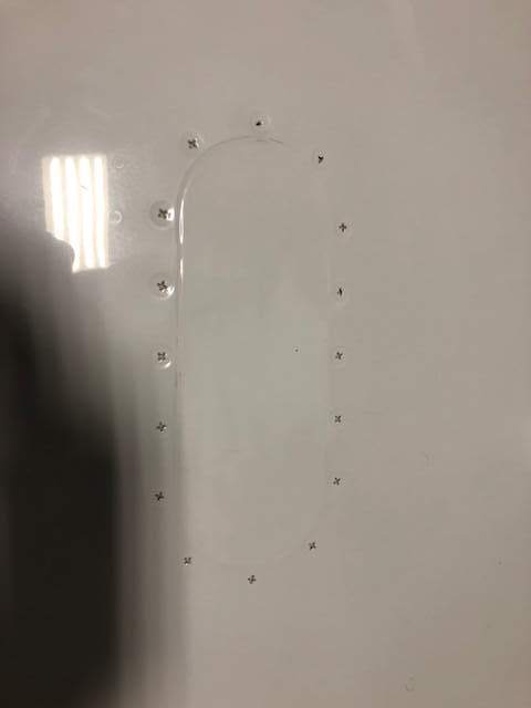
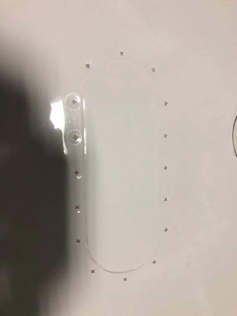
I sent the following email to Precise Flight asking for their help: My equipment: Airplane Mooney M20R S/N 29-0490 P/N 010S0059-73 Rev C, Serial #984455 right hand cartridge. P/N 010S0059-74 Rev C, Serial #984456 left hand cartridge. These two cartridges look identical except for the location of the drain tube. Malfunction: When activated with the button on the yoke the-74 only deploys about ¾” and stays there while the -73 fully deploys. A few seconds later both retract very quickly indicating that the system has automatically removed power from both. Note: Initially this malfunction was intermittent (sometimes the above malfunction existed, sometimes both fully deployed like they are supposed to). Just recently this malfunction exists all the time now. Troubleshooting: First step: I thoroughly cleaning both sides of all connectors; Three connectors on the Asymmetric Logic Control (ALC) and one connector on each wing cartridge. Malfunction still exists. Next step: Swapped the -73 & -74. Malfunction still exists. Next step: Swapped connectors on the ALC, left to right and right to left. Malfunction still exists. Next step: I borrowed a known-good -73 cartridge off of a friend’s airplane of the same model. I tried all six combinations and found the following: 1. My -73 on the right, my -74 on the left. Original configuration, malfunction exists. 2. My -74 on the right, my -73 on the left. Malfunction exists. 3. His -73 on the right, my -74 on the left. Functions normally. 4. His -73 on the left, my -74 on the right. Functions normally. 5. His -73 on the right, my -73 on the left. Malfunction exists. 6. His -73 on the left, my -73 on the right. Malfunction exists. These results led me to believe something is malfunctioning in my -73. Also, I think it verifies that my -74 is good since it works as designed when mating it with a perfectly functioning -73. I’ll fill y’all in on the final result when I get word back from Precise Flight.
-
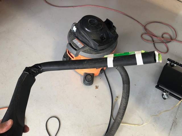
For those of you who work on your own airplane but don't always have someone present to help you remove and reinstall the lower cowl, here is a YouTube video which shows how to do it without chipping paint or scratching the spinner. This jack makes it safe and efficient and it's easy/cheap to build.
- 31 replies
-
- 16
-

-

-
When I first got wing jacks for my Ovation I jacked it and left it overnight with gear down. When I returned the next day both jacks were down and one of them had leaked oil all over the hanger floor. Since then I block the jacks to prevent lowering. Another good reason to block the jacks is that one could leak down causing a gross mismatch in height and a possibility of the airplane slipping off of the jacks.
-
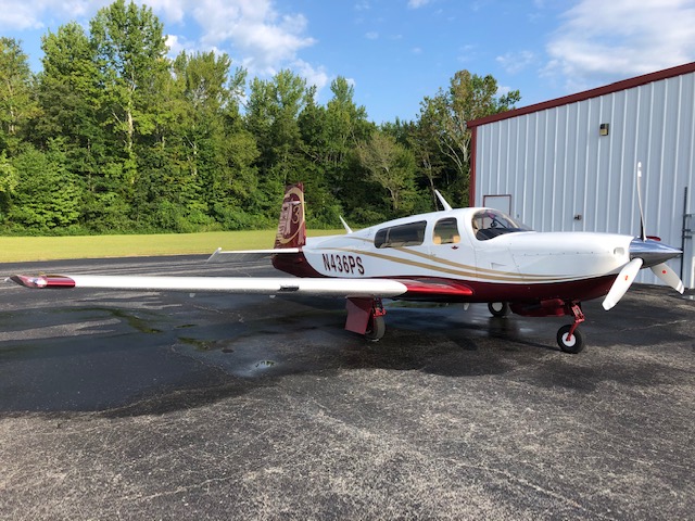
I just flew N436PS, a 2008 3GX Ovation from KMHK to KJWN a few weeks ago at 15K. I was able to get slightly over 60% power (based on the 310hp tables), LOP, 13.5gph, WOT, 2,600RPM and 183kts TAS.
-
My panel and glareshield dimmers were not working when I bought my Ovation 3 when I bought the airplane. I disassembled the control box (mounted on the aft side of he aft blackhead of he baggage compartment) that others have talked about. I found that someone had installed one of the voltage regulators backwards which allowed the pins to short out against the heatsink and that burned out one of the resistors on the circuit board. I replaced the voltage regulators and resistor and it works fine now. I have another post on Modern Mooney which shows a pic of the components.
-
Anyone know where the roll servo is located? 80 M20K. Thanks
JimK replied to willerjim273's topic in Modern Mooney Discussion
This may not be helpful since you have a K Model but, on an Ovation 3, the roll servo is below the instrument panel in the center console just below he engine controls. -
M20S Replacing Rheostat Box with Dimmers - Wiring Question
JimK replied to Darrolio's topic in Modern Mooney Discussion
My glare shield and instrument lights didn’t work on my Ovation 3 when I bought it. I took the dimmer box apart and found two things wrong. 1. Someone had installed one of the large voltage regulator transistors backwards which caused the pins to short out against the clearance holes in the heatsink. 2. When it was powered up the shorted pins caused the transistor and a resistor to burn up. I replaced the those components and the lights work fine now. I had to order more components than I needed so I have some if anyone else finds that their box has the same problem.
-
Batteryminder Y connector permanent connection?
JimK replied to r0ckst4r's topic in Modern Mooney Discussion
I agree with Fritz1. I have a similar setup with an RTA-2415 accessory connection cord hard-wired to each of my two Concord batteries on my Ovation 3. Both of the Battery Minder SAE plugs on these connectors are zip tied to the mounting bracket behind the oxygen service door. It is a very convenient setup because I just open the oxygen service door, pull out the two connectors a few inches and connect them to the 210-AY multi battery connector which I leave connected to my Battery Minder charger. This setup keeps the two batteries isolated from each other and makes it quick and easy to connect the charger after a flight.