

atpdave
-
Posts
53 -
Joined
-
Last visited
atpdave's Achievements
")


-
This is one of the “best” thread hijacks I’ve ever seen.
-
What fuel flow are you seeing with takeoff power setting? Assuming 280hp (full throttle, full rich, 2500 rpm at sea level), in my experience if it's less than about 23.5 GPH (per Mooney) it's set too low. CMI says 22.5 max but that's a little low, my guess is to make fuel consumption numbers look better (see Continental M-16 and Mooney MAN161). If you can lean it out in cruise and get significantly lower CHTs with smooth operation then it's likely a fuel setup problem. Previous owners of my plane were based in Glenwood Springs CO at 5916 MSL, and the logs indicate that they had been messing with the fuel flow, maybe to lean it out at idle. I'm based in Santa Fe NM at 6349 MSL and never saw max power CHTs above 400 around here, but in Texas that first summer they got up to 430-440 full rich, which got my immediate attention. I never saw numbers like you're seeing. The first shop that did the fuel pressure/flow setup for me still set it low, but it was an improvement. When Maxwell did the 310 hp upgrade they got it right IMO and there's plenty of fuel now to keep CHTs comfortably lower during takeoff and climb-out from sea level. In cruise I operate LOP and my CHTs are between 270 and 330 with cyl. 5 always hottest. If you do buy the plane and find you need to adjust the fuel pressure/flow, I suggest you employ someone who is very familiar with the Continental/Mooney-specific fuel setup procedure.
-
I still believe airworthiness inspections should be good for 24 months instead of 12. It’s not reasonable for a plane to be out of service for a month or more every year.
-

Starter Adapter now, new airplane is snakebit!
atpdave replied to Ragsf15e's topic in General Mooney Talk
I had my adapter overhauled earlier this year when it quit cranking the engine on battery power. Luckily a GPU was available, the engine started with the higher voltage, and away to the shop I went. I replaced the Iskra starter with an overhauled Energizer at the same time. Before it gave out, I had noticed the engine was becoming harder to start but didn't know why (I didn't notice that the engine had been cranking more slowly during start). The engine spins super fast now and it starts immediately, within one revolution. Hot starts are much easier too. This problem had been slowly getting worse over time, reminding me of the story about how to boil a frog. -
All non sequiturs. The point is this - I've been safety pilot many times, and it has never occurred to me to disable an aircraft system while performing that role. It's not training, although I have the initials to do it if asked. You sound pretty sure of yourself, but if your friend had reported what you did to the feds, you wouldn't have a leg to stand on.
-
Ovation Cigarette Lighter Adapter
atpdave replied to Healthpilot's topic in Modern Mooney Discussion
The cigarette lighter socket in your plane (SN 29-0464) is connected with a 16GA wire to a voltage converter (output voltage 13.7-13.9VDC 5A) mounted on the tailcone bulkhead. The 5A inline fuse for the converter is attached to battery relay 2. It should have a label (if it hasn't fallen off) that says VOLT CONV or something like that. If the fuse isn't blown then the converter is probably fried. The good news is they can be found online for cheap, even on eBay. Search for Transelectric SM2412-5. I think these things were used on golf carts. -
Last year I had this happen after the plane came out of an annual airworthiness inspection. Previously the mag drop was 20ish both mags. Had the timing checked and one mag was set 20d btdc and the other was at 24, both out of spec. Had the mags retimed to 22 and the problem went away.
-
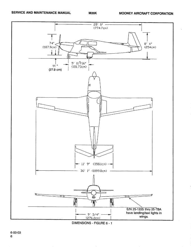
I'm pretty sure it's impossible for Lm/n to be 5 inches greater than Lm/r. I have a page for the nose gear steering adjustment from the a M20K SMM, not an M20J, but I think it's the same. It says that the nose wheel axle centerline should be no more than 0.06 inches forward of the trunnion leading edge, measured with a plumb line. It's interesting that the difference in your diagram is exactly 5 inches, the same number as the trunnion distance from the reference datum. Measuring Lm/n is easy. Measuring Lm/r requires that a plumb line be dropped from the trunnion centerline. If we assume that Lm/n was accurately measured and Lm/r was not measured and is off by approximately five inches, your actual CG would be somewhere around 44 inches aft of the reference datum. I suggest that Lm/r and Lm/n be re-checked. Pages from MAN134 SMM M20K.pdf
-
Valid props for STC SA02193CH (310 hp) on Eagle
atpdave replied to htbnjb's topic in Modern Mooney Discussion
I didn’t make that very clear. I was referring to McFarlane, who I think bought Flight Resource. Here’s a link to the STC. -
Valid props for STC SA02193CH (310 hp) on Eagle
atpdave replied to htbnjb's topic in Modern Mooney Discussion
Here's what McFarlane/Flight-Resource (STC holder for MT prop for Mooney) says (I have highlighted):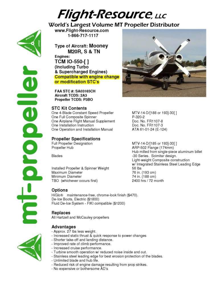
-
Yes. The slight difference is mostly due to the trunnion radius. Compare how the plumb lines are set in the SMM (weighing vs. rigging). I wonder why the distance between nose and main axles in @Marc_B's W&B is 2.3 inches less than that shown in the M20K dimensions figure I attached.
-
@druidjaidan, in the W&B sheet you show in the third post, I think all the arms are about 10 inches too far forward. Just looking at dimensions, weighing and gear rigging info in the SMM, they should be around -5.3 from the zero datum for the nose and +66.3 for the mains. Assuming the weights (and my calculations and assumptions) are accurate, the CG for your plane should be around 41.5 (no fuel) and 42.8 (full fuel).
-
ELT Battery (am I getting ripped off?)
atpdave replied to TigerMooney's topic in Modern Mooney Discussion
Here's one that I know of personally, December 1981. Steve Smart was an acquaintance of mine. He became a preacher after that. No flight plan was filed and no one knew they were missing. -
I had this done recently. Attached (hopefully) are the takeoff and climb charts from the POH supplement. I still cruise at 2400 rpm as before although could do 2550 post-mod. Pages from POH Supplement-2.pdf
-
I think having airworthiness inspections valid for 24 months might be a good solution.


