Vance Harral
-
Posts
1,472 -
Joined
-
Last visited
-
Days Won
5
Content Type
Profiles
Forums
Blogs
Gallery
Downloads
Media Demo
Events
Everything posted by Vance Harral
-
This is the reason I have a hard time getting worked up about NORDO traffic. I'm convinced that most of the airplanes the pearl-clutching crowd thinks are NORDO, actually do have one or more radios onboard. But honest mistakes are made tuning or flip-flopping radios (and ironically, it's sometimes the person complaining that's actually on the wrong frequency). Sometimes the receiving pilot turned down their radio volume and forgot to turn it up. Sometimes the transmitting pilot has a mic or audio panel problem they haven't recognized. Sometimes the person complaining that an offending aircraft "made no CTAF calls" simply missed the call(s) actually made by the "offender" - and by the way, this sort of miss is made increasingly likely the more that everyone wants to have lengthy conversations on the CTAF about what their plans are for the next several minutes, and negotiating deconfliction with some other airplane nearby in the pattern on which they've fixated. I've seen every one of these situations as an instructor, and - gasp - committed a few of them myself in 35 years of flying. Bottom line, the idiot you think is NORDO may indeed be an idiot. But the odds they're actually NORDO just because it's legal to do so, are pretty low.
-
Portable ADS-B receivers are more susceptible, but they're not the only reason for ghost targets. You can get ghosts even with a panel-mounted ADS-B in/out transponder, and even when Foreflight knows the N number of your ownship. Most manufacturers of traffic displays have a little treatise on it. Foreflight's is at https://support.foreflight.com/hc/en-us/articles/225240087-Why-do-I-see-a-false-or-ghost-traffic-target-in-ForeFlight-Mobile . Garmin's plays it closer to the vest, but if you dig, you can find some posts about this from Garmin employees on Beechtalk and elsewhere. In my experience, ghosts seem to be correlated with maneuvering. I do a lot of maneuvering as a CFI, and my recollection is that ghosts tend to show up during steep turns, steep spirals, lazy 8s, etc. I'm sure whatever processing takes place in the stack is biased toward straight and level-ish flight.
-
 Same at Longmont. But my one of my favorite instrument scenarios around these parts is to pretend it's 400 OVC (every great once in a while it actually is); and that we've decided to depart anyway (not unreasonable, given that in the event of a problem shortly after takeoff, there are three airports within a few minutes' flying time with precision approaches to 200' AGL). Controlled airspace starts at 700' AGL. If you're in the soup at 400' AGL, you can't VOCA, and you've got 300' of climb during which your only guidance is the ODP. This gets more interesting when the prescribed heading for entering controlled airspace is different from the radial intercept heading prescribed by the ODP (it usually is, though often not by much). All this makes for a busy departure workload: into the soup almost immediately after takeoff, right at the point you're supposed to start your ODP-prescribed turn. You already need to be thinking about identifying GLL if you've chosen to actually use your VOR radio for the ODP. And then, while possibly still in the original turn, a new turn to the ATC-prescribed "on entering controlled airspace" heading at 700' AGL. Between 700' AGL and 1000' AGL, you should be switching to the departure frequency and attempting to check in, but note that they probably can't hear you until about 1200' AGL. Don't forget your post-takeoff checklist, generally at 1000' AGL. If it's a simulated IMC training flight where I'm pretending to be Denver Approach, I'll often fail to respond to the pilot's initial check-in attempt(s), and see what they do. Hold heading while waiting a few seconds and trying again? Turn back to the ODP intercept heading to re-acquire the ODP? Try to figure out what the "vector" rules for lost comm mean when the heading you were vectored onto actually takes you away from the course in your clearance? It's a fun exercise, and really healthy for gaining proficiency and confidence. Mostly what I want to see is that the pilot (a) verifies they're steering away from the big rocks just west of the airport; and (b) does something decisive and reasonable, without panic or brain lock.
 -
Under Contract on 1970 M20F! Kudos to Jimmy @ Gmax!
Vance Harral replied to bigmo's topic in Vintage Mooneys (pre-J models)
That's a really great-looking airplane! Love the colors. -
I respect these fears, provided the person expressing the concern understands display zoom scale. I also find them frustrating, because every single "near miss on the tablet without visually acquiring" incident I've had, was one in which the threat target appeared out of nowhere, then disappeared from the display altogether a few seconds later. I've had about a dozen of these in the last 5-ish years. I'm 95% sure they were all ghost targets caused by failed ADS-R/ownship reconciliation, rather than real threats. Because of this, I'm no longer startled when a threat suddenly appears on the display at my same altitude, and I'm not particularly concerned about it. I do look outside intently, but that's the limit of my panic. If I ever die in a MAC that I "should" have seen coming, I suppose it might be because of complacency about ghost targets.
-
There's no ulterior motive in this poll, and probably no useful conclusions to be drawn. I'm just generally curious, and figured I and others might be surprised by the responses. Note that there is no universally "correct" answer, and I'm explicitly requesting that respondents refrain from criticizing other's votes. Assume you're flying in a relatively busy metropolitan area, and you recognize converging traffic, that winds up passing "close" by you. At what point does the event change from an everyday occurrence you've forgotten by the time you're tying down, to a scary story you tell for weeks/months/years after? For the purposes of this poll, it doesn't matter whether you initially acquired the threat visually or on ADS-B, and it doesn't matter how/if you maneuver to avoid them. Assume we're talking about piston single speeds here - maximum closure rate of 300 knots in the worst case, head-on scenario; but more realistically in the range of 100 knots. At what point does your sphincter tighten, and you feel compelled to "do something": maneuver, cuss, yell on the radio, whatever?
-
Unapproved radio calls poll, which are you?
Vance Harral replied to 201er's topic in General Mooney Talk
This may or may not be allowed by their rules, but I'm not a controller. Controllers have a tough job, I have great respect for them. But they're only human, and sometimes they get it wrong. Last week, I listened to what was obviously a new student pilot, struggling to read back a taxi clearance at a multi-runway towered airport, that involved crossing one runway and holding short of another. This airport is known for training ops, students need taxi and pattern/landing clearances repeated probably 100 times per day. The instructor on board was allowing the student to struggle. It was a busy day, so maybe that was a bad call by the instructor. But it's essentially always busy, and I've done similar (how else to learn?) It wasn't so busy that safety was compromised - at least not in my opinion. After the 3rd readback mistake, the controller was over it. Fair enough. The appropriate action would seem to be calmly saying something like, "Nxxxx, have your instructor read back your taxi clearance". Instead, the controller groused on frequency, "Nxxxx, your instructor isn't doing you any favors!" They probably thought this was an appropriate tough-love message to the instructor. But from my 3rd-party vantage point, what it accomplished was to teach the student their instructor was unreliable, and also that the student should fear controllers even more than they obviously already did. Not a great look, and if I'd been sitting in the right seat I'd have been righteously P.O.'d about it. -
Unapproved radio calls poll, which are you?
Vance Harral replied to 201er's topic in General Mooney Talk
With due respect, I can only say that this opinion seems to be based on narrow experience. You know the biggest flight training schools in the world all operate out of towered, airports, right? KDVT, KPRC, KDAB, KGFK to name a few. Have you been to any of those towered airports? Ever been to KBJC in the Denver area during the weekday morning "push" of students from ATP? I've flown at 4 of these 5 airports at least once, and the mix of brand-new student pilots (some with poor command of English), and low-time instructors, makes for some pretty amazing experiences. You know that arguably xenophobic joke about the student pilot who responds to, "Say on course heading", with "Rog-ah, on course heading!!!"? That's not a joke to me. As God is my witness, I actually heard this exchange take place between tower and an outbound UND aircraft, while inbound to KGFK. Other than that, I respect, appreciate and agree with everything else said in your last post. -
Unapproved radio calls poll, which are you?
Vance Harral replied to 201er's topic in General Mooney Talk
I've tried internet searching this on a couple of occasions, and have never found a Paul-Bertorelli-style scientific treatment. The best info I have is the accident stuff that shows up in my FIRC, which is pretty sparse. Mostly what the data indicates is that mid-airs are rare events, which makes them hard to analyze statistically. To study the last 50 mid-airs in the United States, you'd probably have to look back at least a decade, and if you try to use data from 2014, people will understandably (and maybe correctly) argue that the world is different now. For what it's worth, I'm aware of four mid-airs in the Denver Metro area since I moved here in 1997. None occurred in the traffic pattern at an uncontrolled airport. One occurred in the traffic pattern of a controlled airport (KAPA, 2021). One occurred under the shelf of the Denver Class B, involving two aircraft that both departed controlled airports (KAPA and KBJC, 2003), one of which was receiving flight following and the other not. The other two accidents (2012 and 2022) involved airplane pairs that both departed uncontrolled fields, but the actual collisions occurred several thousand feet and several nautical miles away from any airport. So four MACs in 27 years, but in three of the four, the airport environment wasn't a factor. This is anecdotal data involving only one metropolitan area, so not really any good for statistical analysis. But even so, I feel pretty confident saying there is "no evidence" that controlled airports are statistically less likely to experience a MAC vs. uncontrolled airports. Again, if someone has actual data to the contrary - as opposed to just their personal scary story - I'm all ears. -
I agree that programming this into a modern navigator is a good "mental push-ups", exercise that helps you become even more familiar with your equipment. Having said that, I confess to feeling a bit old-man-ish about an ODP that involves nothing more than flying a heading to intercept a VOR radial. Even though I'm pretty proficient with my GTN650, I find it to be less trouble and less distracting to "program" these sorts of ODPs simply by setting the appropriate frequency and OBS in my #2 VOR prior to departure, and leaving the GTN out of the equation. I take off, climb to the prescribed turn altitude, turn to the prescribed heading, ident the VOR and wait for the CDI needle to center. One reason I like this strategy is that in large metropolitan areas with Diverse Vector Areas, ATC is often going to vector you off the ODP as soon as you check in with them anyway. Because of this, having the ODP in your primary navigator ahead of your cleared route is arguably irrelevant. It can actually be a distraction, though not much one for anyone proficient with flight-plan-ology. My strategy does assume one is comfortable with a good old fashioned VOR receiver and CDI, and I've certainly had a few clients with fancy avionics, who just aren't. They really need the comfort of a magenta line on a moving map to feel confident they're not going the wrong way. And in some cases, they just really, really want to be able to fly everything with an autopilot, which can add challenges based on the autopilot's connectivity with one or both VOR receivers. So yeah, I can and do teach them how to paint a VOR radial with their GPS - you've got to meet people where they're at. But those clients are also the ones most likely to suffer an unfortunate, simulated #1 navigator failure during training.
-
Again, I don't find this to be true in practice for people who most need the training. The visual display is similar, but the interface just isn't. Think about what's required to set a VOR course using the (virtual) "OBS knob" on a G5 vs. a GDU 700. Or to set a heading bug and the baro setting (two independent knobs on a dual G5, one singular knob on the GDU).
-
If you're fortunate enough to have a modern com radio, it can often "monitor" the audio of the standby frequency (muting it when there is audio on the primary). And you probably already have your standby tuned to the CTAF of the place you're going, so this is easy-peasy. I teach this trick a lot.
-
Unapproved radio calls poll, which are you?
Vance Harral replied to 201er's topic in General Mooney Talk
One interesting thing to discuss in this thread is, "How close is close?" For better or worse, people with a lot of experience - particularly experience at uncontrolled fields - have a much less conservative definition of "close" and/or "crazy". Things that I don't think are unsafe or scary, bother other pilots. Not saying I'm right and they're wrong, it's just an honest difference of opinion. About a month ago, my airplane partner and I were ready for takeoff at our uncontrolled airport, on an unusually slow afternoon. The only two aircraft on frequency were ourselves, and an airplane inbound on a practice VOR-A approach. It's important to understand the nature of this VOR-A approach: it's perpendicular to the only runway, has an MAP directly over the center of the field, and has an MDA that is 600 feet above the ground. I've flown the approach many times myself, it hasn't changed in decades. I know exactly where the approach path is, where the missed is, and where airplanes flying it are likely to be, including error tolerances for pilots new to instrument work. The inbound aircraft had been making good position reports on the way in, and I had their target on ADS-B. Shortly after they called, "3 miles south", we called entering the runway, for takeoff. The inbound aircraft immediately responded, reported 2.5 miles south, and actually issued us an instruction to hold short while they completed their approach. I didn't want to be a jerk, but I did politely say something to the effect of, "We're not a conflict, we can't climb to your altitude by the time you're here, and we won't be in the approach path anyway. Departing Runway XX." The other pilot was highly offended by this, fired off a mini rant about how this was "just completely unsafe", and announced they were breaking off the approach early to avoid us. They undoubtedly went home - almost certainly to their towered airport - and told their friends about those jerks at uncontrolled airports that just do whatever the f**k they want with no regard for safety. I see the same sort of thing with the local jump plane, which descends from "divers away" at thousands of FPM, and at indicated airspeeds approaching 2x of the typical 172. They will sometimes pass other aircraft on a wide, descending downwind to slot themselves forward into a perfectly reasonable empty space (especially given the 747-size patterns some of the piston singles fly). This looks perfectly safe and reasonable to those of us who operate here every day. It seems crazy to someone who has never seen it. Occasionally there is an indignant "you cut me off" complaint on the radio about this, and I'd bet more than one report has been filed over the 20+ years they've been doing this. The FAA has never done anything about these reports, to my knowledge, and most of us like it that way. A good place to observe differing opinions about "close" is on the recently-established practice area frequency in our high-density training area. I wish the pilots on it would just report their position, and refrain from having ATC-style interactive conflict resolution conversations. But I try to play nice. Anyway, I'll sometimes get a call from some other aircraft, "Nxxxxx, are you on frequency?" I can tell the other aircraft wants to play the conflict resolution game. But sometimes that other airplane is 5nm away, and we're both in 172s. If we immediately turned head on toward each other, it would be 2+ minutes before we were anywhere even remotely in the vicinity of a MAC. 5nm isn't remotely "close" to me, but I'm sure it looks kinda threatening to the low-time students (and instructors) at the local, towered-airport flight school, who have never operated without ADS-B and who don't really understand the zoom scale on their EFB. I know essentially nothing about ag ops, but I suspect some of the same things are at play in some of these ag plane conflict stories. Ag pilots are flying highly maneuverable aircraft, and are proficient in aggressive, low-level maneuvering flight. That doesn't excuse the pilot in @Schllc's story, because they were unquestionably a jerk. But I wouldn't be surprised, if one talked to him/her about it, that s/he would say the "near miss" was actually nothing of the sort. Again, to be perfectly clear, I am not saying the ag pilot was right and Schllc was wrong. What I'm saying is that you observe something that seems scary at an uncontrolled airport, and decide to take your marbles and go home because of it, you subsequently lose out on the opportunity to observe a lot of "scary stuff" happen without any actual problem. But that's everyone's right, and if doing so makes you feel safer, more power to you. We're fortunate to live in a country that supports both towered and untowered operations. -
Unapproved radio calls poll, which are you?
Vance Harral replied to 201er's topic in General Mooney Talk
And sometimes adding a tower makes an airport less safe and efficient, despite what I'll charitably assume are legitimate intentions. Such has been the case at KFNL. When that tower is in operation, they close the crosswind runway, and require all pattern operations to be west of the main runway, because - get this - that's the only direction they can see. The "tower" is actually nothing more than a trailer, a transmitter, and a guy/gal with binoculars. They also direct all inbound traffic to sequence over a singular point, driving all inbound traffic to close into conflict. I grant this is a special case, but it goes to @Schllc's question of, "Why have ATC if it doesn't make things safer?" The real answer is that ATC is added based on arguments of safety, that sometimes turn out to be more grounded in politics or other factors, rather than any actual safety. One could just as well say, "Obviously presidential TFRs are legitimate, why would we even have them if they're not protecting the president"? -
If you're talking about the full-blown GAT that runs on a PC, not very often. The challenge with it is that the folks who would benefit the most, are generally too distracted by the fact that I can't make it exactly match their panel. Mainly this involves the ADI/HSI display, but I also can't model the GNS navigators in it. The PFD/MFD options in the trainer are the GDU 620 or the TXi system, but common equippage amonst my clients is G5/GI-275. I can point out that a GDU 620 PFD is more or less the same view you'd get on a pair of G5s, but the buttons are different. But the people who are fine with this are already pretty savvy with advanced avionics. The people who most need training have a hard enough time with the equipment in their actual airplane, and the distraction of operating something different in the trainer is generally a net loss. For the navigator, I can tell someone that the logic in a GTN is the same as the GNS. But this is a hard sell, between the legitimate differences in the UI, and the inevitable "I hate touchscreens" side dish served up by the client. So I have to go back to the really ancient PC trainer for the GNS navigators, or convince them to pony up $65/hour for the Redbird simulator at our local flight school - which has one simulated airplane that models GNS navigators and steam-gauge ADI/HSI, but almost never matches their airplane, much less their panel. Adding all that up, the promise of simulation is usually greater than the actual benefit. It's too bad, because I think simulation is a great tool. I do wish Garmin would undertake the singular effort to add the "little" ADI/HSI instruments into their GAT (G5 and GI-275), but I'm not holding my breath. Guessing there are technical challenges in doing so. Really this just goes back to the baseline problem with advanced avionics training, which is that there's so much variation in the operation of each gizmo, that it's a problem even for the simulators and trainers. It's diverse enough within the Garmin universe, that even Big G can't seem to release a trainer that covers the most common GA equippage.
-
Best point from this good post. The crab angle and ground speeds you observe leading up to landing are not necessarily indicative of the wind you'll experience in the flare. That doesn't mean you should wait until the last second for a go-around if you don't like what you're seeing. But there's also nothing wrong with continuing an approach from 400' AGL to 100' AGL to see if the winds are more favorable closer to the ground.
-
Unapproved radio calls poll, which are you?
Vance Harral replied to 201er's topic in General Mooney Talk
Right. At towered airports, you're (mostly) obligated to do what others tell you. Such as be turned onto final at the same time other traffic is on the same final and have to take evasive action. Such as be told "do a 360" at the base corner, over the top of other traffic inappropriately vectored in on a long base, and asking for you to turn your back to all the other traffic; then not be given instructions what to do afterward, and causing a TCAS RA for the jet on final (this happened to me just last month). Those are just a couple of my towered airport stories. All the things you say about untowered airports are true, and increase risk. But you're suffering from the illusion that towered airports are consequently "safer". On the contrary, they just have different risks. They're often even busier, causing more traffic density, more potential conflicts, and added workload to pilots to follow instructions that can't always be predicted or anticipated. More importantly, the tower controllers are human, too. Sometimes they have a bad day, just like people on the CTAF. Sometimes they're on the wrong frequency, just like people on the CTAF. Sometimes they're trainees, just like people on the CTAF. All of those things increase risk, too, and I've experienced all of them. The last midair in the Denver metro area was at KAPA, a busy towered airport. There's never been a midair in the traffic pattern at my local uncontrolled field. Yeah, yeah, I know, you're going to tell me the guy at KAPA in the Cirrus was an idiot and "failed to follow instructions". But he thought he did what he was told, safe in the warm embrace of a tower controller. So both types of airport have risks. There's no evidence in accident data that one kind is actually safer with respect to bending metal, maiming, and death. Just a bunch of anecdotes from people that like one or the other, almost always for no reason other than that's what constitutes the bulk of their experience. If you've got actual data to refute this, I'm open to discussion. But for every crazy story you've got at an untowered field, I've got one at a towered field, and without data we're just talking past each other. -
Nothing wrong with that, but let me present you with a real-life scenario that requires some challenging ADM. It's a busy day at uncontrolled KLMO (which it nearly always is). You arrive at the airport the morning after your ski trip, listen to the AWOS, and winds are 160 at 5 knots, technically favoring runway 11 with a 3-knot headwind component. You notice the pattern is full of aircraft using Runway 29. Per your personal minimums, you broadcast on the CTAF, "Mooney is taxiing for runway 11". Someone responds, "Traffic is using 29". You call again that you're taxiing for 11, and no one responds. You key up again from the runup area with, "Anyone want to switch runway direction?", and someone finally takes pity on you and says, "per local procedures, Runway 29 is favored in light winds" (there's an actual reason for this, but no explanation is offered to you on the CTAF). How long will you sit in the runup area for Runway 11 waiting for reasonable spacing to take off, or for the winds to change? 5 minutes? 10? 30? This is not a made-up scenario, it's real life at my home 'drome. How principled are you? Do you know if you can safely take off from the 4800' runway in your airplane, on that day, at your weight?
-
Unapproved radio calls poll, which are you?
Vance Harral replied to 201er's topic in General Mooney Talk
Because people often get it wrong. Less so in the ADS-B era, but I can't tell you how many times I've heard airplanes call "number two" when they're really 3rd in the sequence, because they're unaware of some other airplane in the pattern they haven't yet spotted. As with a lot of things, bad information is worse than no information at all. I'm not particularly interested in people calling their number in the sequence, because it doesn't help me find them. I'd a whole lot rather they just report where they are. Tell me you're mid-field downwind, or abeam the east numbers, or abeam the west numbers or making a turn (to crosswind, downwind, final). All of those things are more helpful than saying you're "number four". What useful information does "number 3" add to this call? Isn't "Bonanza left downwind 36 behind the Mooney" just as good? -
Unapproved radio calls poll, which are you?
Vance Harral replied to 201er's topic in General Mooney Talk
TRUTH...... Well... there are problems with this sort of black-and-white thinking. Not all uncontrolled airports have the same traffic density. At your home 'drome, "any communication is welcome" is probably a fine philosophy. At mine, it would be a disaster. There is simply too much traffic here for everyone to say whatever they want/think is helpful, whenever they want/think is appropriate. For better or worse, crisp professionalism matters here in a way it doesn't elsewhere. That doesn't mean it's an unpleasant environment for non-locals, or that mistakes are unforgivable. Just that local stakeholders would prefer transients strive for pro standards. That's true at a lot of other uncontrolled airports as well. But that doesn't mean those of us based at high-density training airport should pick a fight when we go out to Podunk regional, and hear "Blue biplane entering the downwind, how's the BBQ today?" More generally, a large part of what drives these arguments about best CTAF behavior is the reality that different airports have different demands, character, and - most notably - local procedures. Such as... At my uncontrolled airport, this would mean you both missed the remarks in the Chart Supplement, and also didn't listen to the message on the AWOS, that directs pilots to avoid midfield overflights due to skydiving operations. Yes, there is a local procedure here that directs pilots not to use the overflight techniques specifically suggested in AC90-66C. It's true you can sorta avoid this kind of problem by only patronizing towered airports, and reporting to the controller that you're unfamiliar (towered airports have a different set of risks, but that's a discussion for another time). But the best pilots I know frequent lots of airports - both towered and untowered - and as such understand that best practices actually depend on the particulars of the airport. This is challenging, and frustrating, since of course you can't be intimately familiar with "local procedures" everywhere in the country/world you might wish to fly. One longs for standardization, and singular correct behaviors. But despite the AIM, AC90-66C, and any number of other publications, that's just not the way communities work. To end on some good news: First, there is a somewhat finite set of challenges at uncontrolled airports: some have skydiving, some have right hand traffic patterns, some have intense practice instrument approach activity, and so on. If you adventurously seek out places to fly, don't fear the CTAF, and get enough practice to see for yourself how casual radio work actually decreases safety, you'll eventually get comfortable with the challenges just as with other aspects of flying. Then the CTAF world doesn't seem like such a scary, wild-west kind of place. Second, the FAA has finally got on board with acknowledging that every airport has unique challenges, and employing multimedia to get the word out on airport-specific concerns. Their From the Flight Deck series is excellent; and while that focuses on towered airports for now, I'm hopeful it will be extended to high-density uncontrolled airports in the future. -
I didn't vote in the poll because the options are too static, as others mentioned. One thing that hasn't been brought up yet is that my behavior varies a little if I can make a pretty good guess about the capabilities of the other pilot(s) on frequency. Consider being straight in on an RNAV practice approach and hearing: Foobar traffic, bugsmasher 12345, midfield downwind for XX, we can extend for traffic on the RNAV. ... versus ... Uh, Foobar traffic, this is... November 12345.... downwind... for... runway XX, student solo... Foobar. In the latter case, I'm happy to maneuver in a way that lets N12345 fly what seems like a normal pattern to them. That's partly for safety, but mostly for courtesy and kindness. I was a student solo once too.
-
The avionics shop that installs the equipment is supposed to provide you with updated schematics for your aircraft, as part of the installation. But almost none of them do, which is an irritant. The best practical advice I can give clients in your situation is to look at the installation manuals for their equipment, which often contain wiring diagrams that effectively serve as system block diagrams. You may hear that Garmin is persnickety about this, and doesn't publish all their installation manuals - particularly for their GNS/GNX/GTN navigators. But if you just want block diagrams rather than actually installing equipment, there's a workaround: Garmin sells their PFD/ADI/HSI products into both the certified and experimental market, so installation manuals for those products are downloadable, and those manuals contain system diagrams showing how the G5/GI275/G3X is connected to navigators and other equipment. For example, if your airplane has dual G5s, you should look at Section 5 of https://static.garmin.com/pumac/190-01112-10_31.pdf. In particular, Figure 5-12 on p.132 of that manual is a very common configuration for aftermarket dual G5 installations with a GNS/GNX/GTN navigator.
-
Yes, but now we're talking about fine-thread (we used 6-32) machine screws going into 1/4" of plastic, threaded receiver; rather than coarse thread sheet metal screws that just go through two drilled aluminum sheets (with no nut plate on the back!) The rivnut arrangement is considerably more secure. It's been 10+ years since we did the work, and I've never found one of the machine screws backed even the slightest bit out of the rivnut.
-
Cost for SB 208B inspection and repairs
Vance Harral replied to rbmaze's topic in General Mooney Talk
If you want to "cheap out", you can remove a single interior panel and/or use a borescope to look for rust on "some" of the tubes, and assume the rest are comparable. This is what we did when we bought our Mooney, a couple of decades ago, and it only takes about an hour. But I wouldn't really recommend that approach. If you're actually going to perform the SB, the first step is to remove all the interior panels. This is not sophisticated work, at least not in my vintage of Mooney - it's just a bunch of small, non-structural screws. Figure 1-2 hours of labor to remove, and 1-2 hours to re-install. Note that the owner can do this work (not that you're the owner yet, but this becomes relevant later). You're also supposed to pull up the duct tape that provides a seal between the floor panels and the roll cage structure. This is easily replaced, but requires supplies and time. If, after removing the interior panels, you find that the airplane still has the old fiberglass insulation, deduct the cost of the new insulation kit, plus a few hours of labor, from your offer. See https://lasar.com/misc-supplies/insulation-kit-170018-901. After you buy the airplane, you can pay someone to do the work, or you can save a few bucks and do it yourself (R&R of interior panels is owner/operator work, and you can get your own A&P to "supervise" the installation of the closed cell foam insulation). Installing the new installation is not a complicated job, just tedious. Figure 4+ hours of labor if you don't do it yourself. Once you've got the panels off and noted what kind of insulation it has, you can visually inspect all the roll cage tubes, which is the main focus of the SB. But, visual inspection isn't the full extent of it. If you're really doing it right, you should perform all of "Part B" of the SB. This requires removing the tension bolts that attach the roll cage structure to the spar, and running a magnet inside the most critical of the tubes, to see if it pulls out any rust. Hopefully there's nothing significant, and then you get a chance to spray LPS or similar corrosion inhibitor inside that set of tubes. This work is not particularly difficult, but it does involve R&R'ing some very important structural bolts, and it's possible the seller may balk at allowing this to be done by your pre-buy mechanic. If the tubes look in good shape after removing the interior panels, the SB permits skipping this higher level of disassembly, but up to you and the seller whether to do so. The good news is that the procedure for doing all this stuff is well-documented in the SB, so it's not like you're proposing something out of left field to check for corrosion. In my opinion, any reasonable seller would (a) already know all about SB-208 and be able to tell you when/if it was last performed; and (b) allow the SB to be part of a pre-buy if it hasn't been recently performed. -
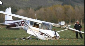
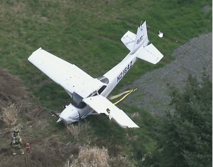
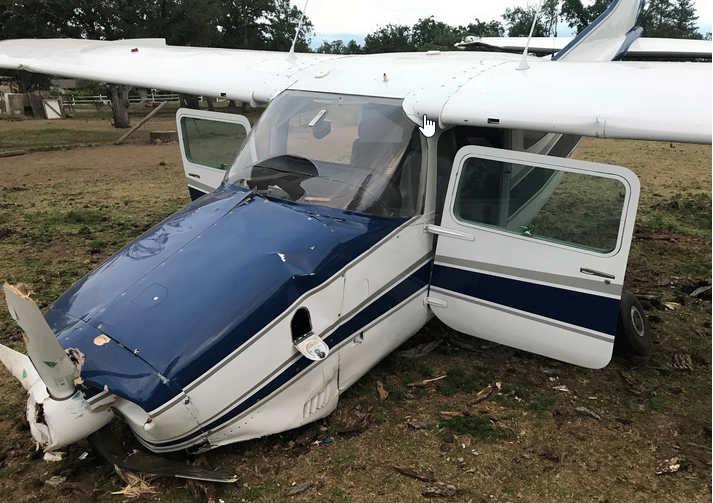
Off-field emergency landing - gear up? gear down?
Vance Harral replied to AJ88V's topic in General Mooney Talk
Plenty of Cessnas remain upright in off-field landings, even ones rough enough to tear up the airplane.