Raymond J1
-
Posts
340 -
Joined
-
Last visited
Content Type
Profiles
Forums
Blogs
Gallery
Downloads
Events
Store
Everything posted by Raymond J1
-

Oil control rings and lessons learned - with pics!
Raymond J1 replied to canamex's topic in Vintage Mooneys (pre-J models)
-I think that the piston best suited to the cylinder of IO 360 A1A is the PNr LW 10207. I think so because this piston has 2 reserves on the top for the passage of the valves and this impacts the flamme front for speeds between 2400 and 2600 rpm. This piston also has the particularity that the scraping side of the "shot" and "compression" rings is upwards, which is not the case with all pistons at Lycoming (not high compression ratio). Finally, and this is important, the oil return holes under the oil scraper segment are larger. -This piston has a disadvantage, the forged skirt contributes to a faster wear of the cylinder bottoms, cause of a downgrading of the cylinder since for this part a limit diameter is imposed. - Chrome rings are not suitable for chrome cylinders... Often we forget about this restriction when we buy new segments. -The major cause of oil consumption is not on this side... Very often, it is necessary to look at the valve guides, especially the exhaust ones, whose clearance is excessive on engines that do not heat up. And very often, the slags deposited on the exhaust valve stem contribute more to the wear of these guides. This is where you have to look for the cause of your technical problems because the pollution of the piston by unburned oil residues is a consequence and not a cause. Since you have opened the engine, also remember to check the oil injector under the piston... There are sometimes interesting things that prevent the proper internal flow / cooling of the high engine. -
The first trump card of the "badman" seems to be that Mooney does not know who has the right weights and who has the wrong ones... The second trump card is that the weight concerned, even in poor condition, is at the right mass, I mean that it is the mass that is suitable for her elevator... In fact, by disassembling the wrong offending weight, weighing it and reconstructing it identically, the wrong thinker can believe he is doing a perfect thing... Especially if he organizes the fusion of the "bad" mass to transform it into the "good" mass... For the moment, I imagine that Mooney must publish the solution very quickly.
-
From the album: The 67 F #26, Fox Juliet November.
-
This haughty vision of technical professions, if it exists, is a good thing for our Mooney, especially to remanufacture a very small rudder counterweight, i.e. 3 hours of milling (instead of the lead foundry) and 1 hour to adjust the tungsten load.
-
I have the number 26 from the end of 1966 (model 67), they are in very good condition.
-
From the album: The 67 F #26, Fox Juliet November.
-
From the album: The 67 F #26, Fox Juliet November.
-
From the album: The 67 F #26, Fox Juliet November.
-
From the album: The 67 F #26, Fox Juliet November.
-

From the album: The 67 F #26, Fox Juliet November.
-
From the album: The 67 F #26, Fox Juliet November.
-
It takes a while...
-
From the album: The 67 F #26, Fox Juliet November.
-
![20220718_163427[1].jpg](https://mooneyspace.com/uploads/monthly_2022_07/small.830764417_20220718_1634271.jpg.5655cb82084979f7206754e7b31145d6.jpg)
From the album: The 67 F #26, Fox Juliet November.
-
Fuel level senders
Raymond J1 replied to warbingtonmasonry's topic in Vintage Mooneys (pre-J models)
On 67 F... https://www.chevsofthe40s.com/detail/30031/Chevrolet_Gas_Tank_Sending_Unit_030_Ohms_For_Gas_Gauge_6V_or.html -
For the original canvas, the gluing is carried out with neoprene glue ("contact" glue among the Anglo-Saxons), which holds the temperature once polymerized (up to 130 ° C (260 °F) without problems). For the silicone canvas, I use a silicone glue for gluing joints (silicone) on the glass doors of ovens, this glue is resistant to 350 ° C (660 ° F).
-
Thank you, but it's not over, we have to explain now why this part disappeared from the engines and what is necessary to do to be able to use it. On the contrary, the conditions for the original part to still be usable.
-
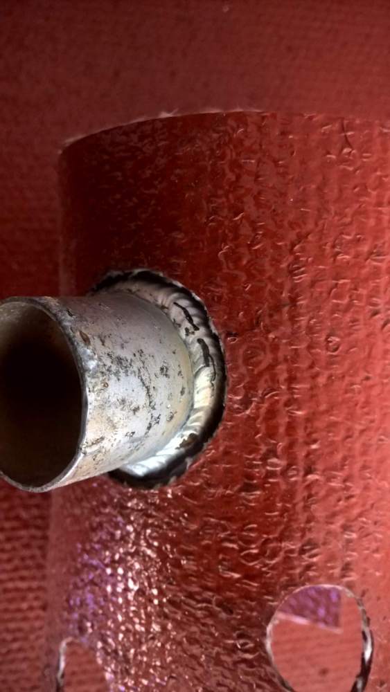
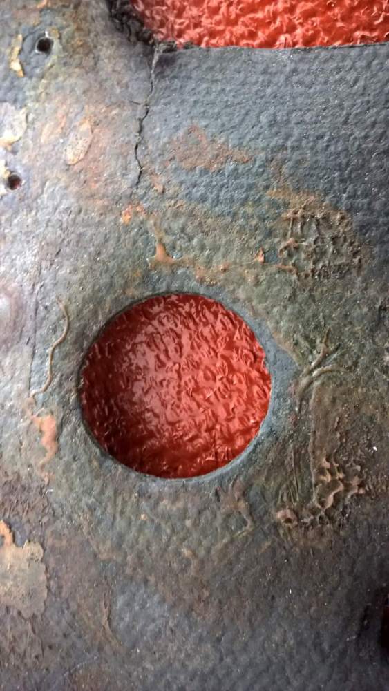
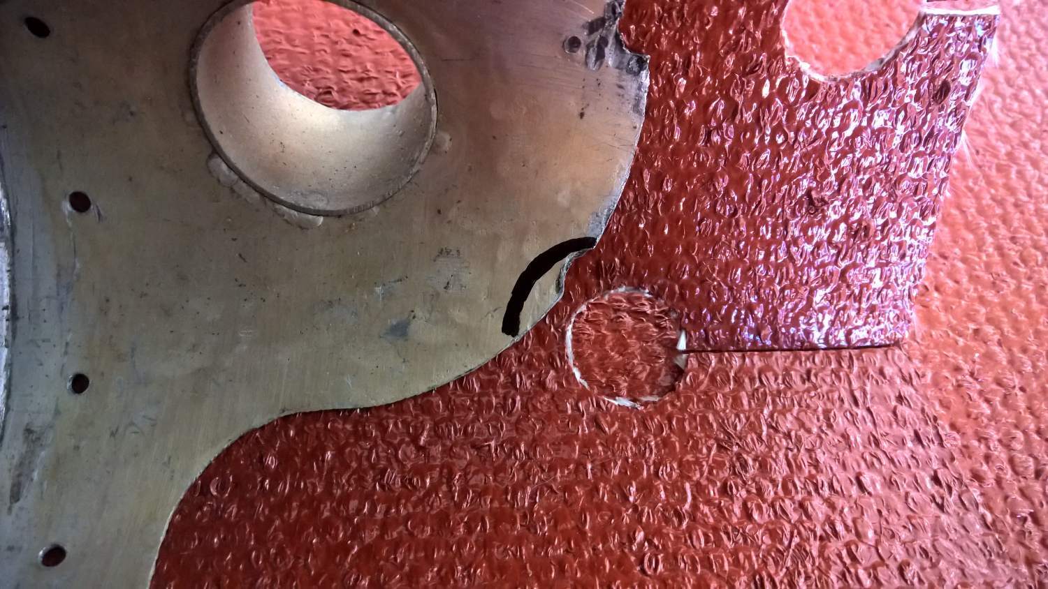
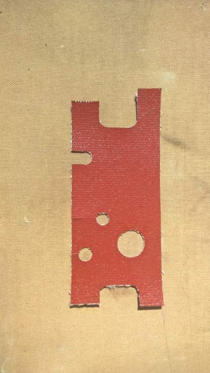
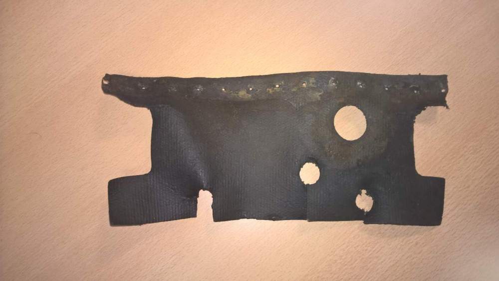
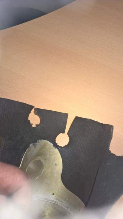
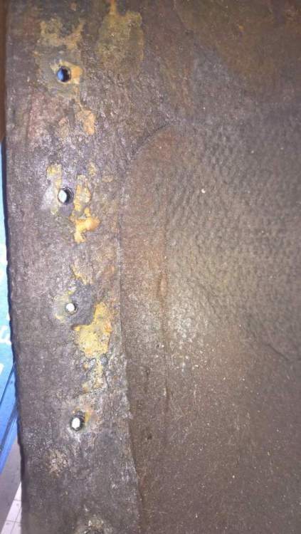
Presentation of the canvas, control and minor changes : Previously, I put photos and a plan of the parts of this gas pump cooling cover such as according to the origin. The disappearance of this hood on most engines has a reason, which I will expose. For me, this part is a safety element, especially for airplanes that operate under warm saisons, it has a real reason to be on the mechanical pump but it is necessary to make modifications, minor and major, so that the reason for removing it is not dominant. Mooney never came back to this part that is not listed in the spare parts manual... Minor change #1, the diameter of the passage for the air inlet duct sleeve. Originally, it is 1" 1/4 in diameter, but the brazing cord does not allow the canvas to be glued properly. To allow a good bonding and also guarantee a better connection length of the scat air duct, it is preferable to make a passage hole whose diameter is 1"1/2. Thus, the weld seam is avoided. Pict 1 : new silicon canvas with 1"1/2 , Pict 2 : Old canvas and the 1"1/4 passage. Note the lack of glue and the deformation of the canvas near the hole, due to the brazing cord of the sleeve Minor change #2, Metal-metal contact reserve due to vibration: In the canvas there is a passage hole for the fuel pump drain. Before gluing, it is necessary to increase the distance between the diameter of the hole in the canvas and the edge of the metal frame of the hood. The minimum dimension of this distance is 1/4", this corresponds to the black felt trace visible in the photo. A cutout along the radius is ideal.


-
The plan for the canvas, with the original dimensions Silicon canvas for fuel pump cover.pdf And the new silicone canvas rebuilt for my engine.
-
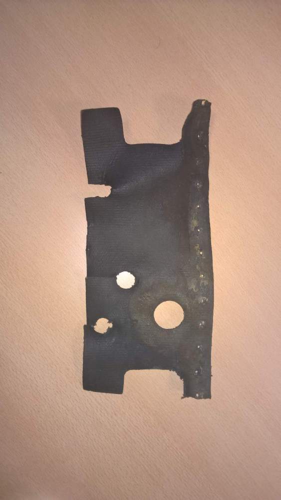
Then the coated canvas which is glued and riveted to the metal cap :


-
Some detail photos for each piece. First the metal structure that caps the pump :


-
Ok, I'll post here the plans of the parts for make the same. I would put some details pictures too. I request just asking to all to wait a few days, I'm on the move for the job.
-
Not exactly. yes, for disassembly I just had to drill the rivets. On the aluminum part which is in Al.Mg 5 welded, there was a bit of boilermaking because the part was forced during an earlier disassembly and the upper part was pressed in. For the "gummed canvas" (this is the general name given in France to these technical fabrics impregnated with rubber or similar). In fact, originally, it is a fiberglass canvas impregnated with a mixed butyl-nitrile rubber, capable of withstanding 200 degrees and whose texture to the touch is "greasy", the rigidity of this 3 mm thick canvas is higher than that of silicone canvas. The temperature limit is sufficient in this area of the motor and as it is written above, this gummed canvas construction and its rigidity / flexibility is important for the behavior of this part to vibration. This speaker has been mounted on the engine since 1966, it has a little more than 5500 hrs of operation and I have not noticed any traces of particular wear on the crankcase, the fittings or even the part itself. The motivation for the reconstruction is only the hardening of the gummed canvas with time and temperature. It is important that the ventilation "scat" sheath does not constrain the mechanical pump cover. If you want to rebuild this part I can put here diagrams of the developed parts, with dimensions in inch or mm and photos.
-
.jpg.e72a1b3775c6f39a7327dd7e1d5e7713.jpg)
From the album: The 67 F #26, Fox Juliet November.
-
In the end, French wine may have got the better of him...