Utah20Gflyer
-
Posts
886 -
Joined
-
Last visited
Content Type
Profiles
Forums
Blogs
Gallery
Downloads
Events
Store
Everything posted by Utah20Gflyer
-
I'm currently upgrading to CIES fuel senders and opted to go with an aerospace logic digital fuel gauge, it costs about 900 bucks. I have a JPI EDM 800 so didn't feel like a primary engine monitor would give me enough extra functionality to warrant the extra cost although someday I'd like to upgrade to clean up the panel.
-

Overhead vent upgrade project
Utah20Gflyer replied to Utah20Gflyer's topic in Vintage Mooneys (pre-J models)
Here is the latest version of a vent lever, this model is made from PETG which should have a UL94 rating of V2. I incorporated a brass threaded insert and increased infill to 50 percent. I think this should last longer than the plane.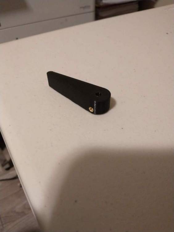
-
Slowing down to lower gear
Utah20Gflyer replied to M20 Ogler's topic in Vintage Mooneys (pre-J models)
I generally fly the pattern at 16 inches so it would be really annoying for the gear horn to go off at 18 inches. As other have said check for the proper number for your aircraft. Mine goes off about 12 inches which seems about right. Generally my rule is to not allow the gear horn to go off without remedying the issue immediately. The intention is to thereby avoid a gear up, tolerating the horn means I may ignore it when it’s really giving me a important input. Being able to do that requires it not to go off frivolously so make sure it’s set correctly. The process of slowing down for me is to level off and reduce power to pattern power (16 Inches) and wait for it to slow to pattern speed (100mph). I try to always be at pattern speed when entering the pattern. Then when I’m abeam the numbers I’m good to go to drop the gear. -
Overhead vent upgrade project
Utah20Gflyer replied to Utah20Gflyer's topic in Vintage Mooneys (pre-J models)
Interesting, yes mine requires removal of headliner but I had to take mine off to address an issue with a rheostat anyway. I'd like to see how your install goes. -
Overhead vent upgrade project
Utah20Gflyer replied to Utah20Gflyer's topic in Vintage Mooneys (pre-J models)
I did previously have that old style vent. The link is to the vent I used. The angle on the vents is right about 30 degrees. I don't know the exact height but it's about 2 inches. The metal insert is a good idea. I was considering it but didn't have any on hand so I went with an undersized hole on the back side of the part so the #4 screw would cut threads into it. Long term after repeated install/removal I expect they will fail. I think I'll order some inserts and integrate them into the design. I appreciate the input. -
Overhead vent upgrade project
Utah20Gflyer replied to Utah20Gflyer's topic in Vintage Mooneys (pre-J models)
Here is the vent lever prototype in place. I think it turned out pretty nice.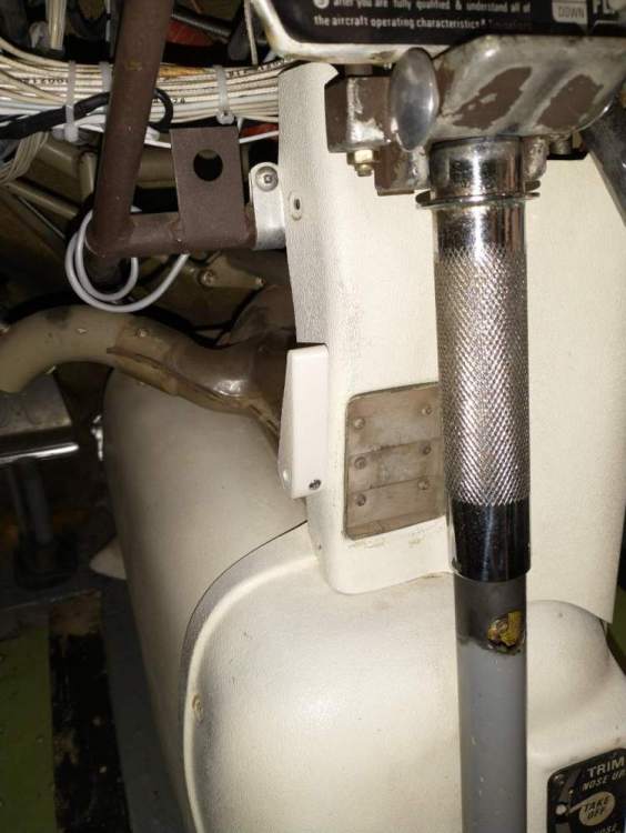
-
Overhead vent upgrade project
Utah20Gflyer replied to Utah20Gflyer's topic in Vintage Mooneys (pre-J models)
I believe the material I'm looking at has a UL94 rating of V0, which I think should be adequate. Still learning and researching though, lots to learn! Private pilot only not an engineer.... -
Overhead vent upgrade project
Utah20Gflyer replied to Utah20Gflyer's topic in Vintage Mooneys (pre-J models)
It's an ender 5 pro but a good guess as they are very similar. I'm looking into an enclosure but following the trend for me in 3d printing everything is complicated. The lower end printers aren't designed to handle operating in a heated area so I need to heat the chamber while also providing cooling to certain components. Also ABS off gasses some stuff I don't want to be breathing so I have to figure out a system to mitigate that. I could buy a printer that does all of this out of the box for 10k to 30k but that seems a little much to Satisfy my desire to tinker at the moment. I'm may get one eventually as it would be cool to be able to do PEEK, PEKK, ULTEM, etc. but That's going to be down the road a ways. For the the me being I think I'll put about 1k into it and see how things go. -
Overhead vent upgrade project
Utah20Gflyer replied to Utah20Gflyer's topic in Vintage Mooneys (pre-J models)
Thanks for the heads up. PC-ABS has a glass transition temperature of 257 degrees putting it about 25 percent over the boiling point of water. Hopefully between having a buffer and not being in the direct flow of the air I'm thinking it should hold up. It looks like the current handle I have is made of abs plastic so should be slightly better. That is the hope anyway. The prototype is made of PLA which has a glass transition temp of around 150 degrees which is not going to cut it, but it's cheap and easy to print which is why Im using it for fit/function testing. Quite a lot of my research so far has gone into learning about the available materials and processes. A lot of the more common materials used in 3d printing are unfortunately not adequate for what I'm trying to accomplish but there are a few with good potential. It comes down to finding materials that are relatively easy to print, strong and fire resistant. Thanks again for the input. -
Overhead vent upgrade project
Utah20Gflyer replied to Utah20Gflyer's topic in Vintage Mooneys (pre-J models)
This is a side note to the original project but just 3d printed my first Mooney part. The vent adapters are a bit advanced as I am just learning CAD, CAM as well as all the variables in materials and 3d printer settings. I needed two vent handles, one for the center console vent and one of the vents under the console at your knee. They are a pretty simple design so I figured I would start with them. This one is just a prototype made from PLA which is not a material I would make a real handle from but I'm going to take this one and check it for fit and function and if everything checks out I will work on making one out of PC-ABS FR (fire resistant plastic).
-
Overhead vent upgrade project
Utah20Gflyer replied to Utah20Gflyer's topic in Vintage Mooneys (pre-J models)
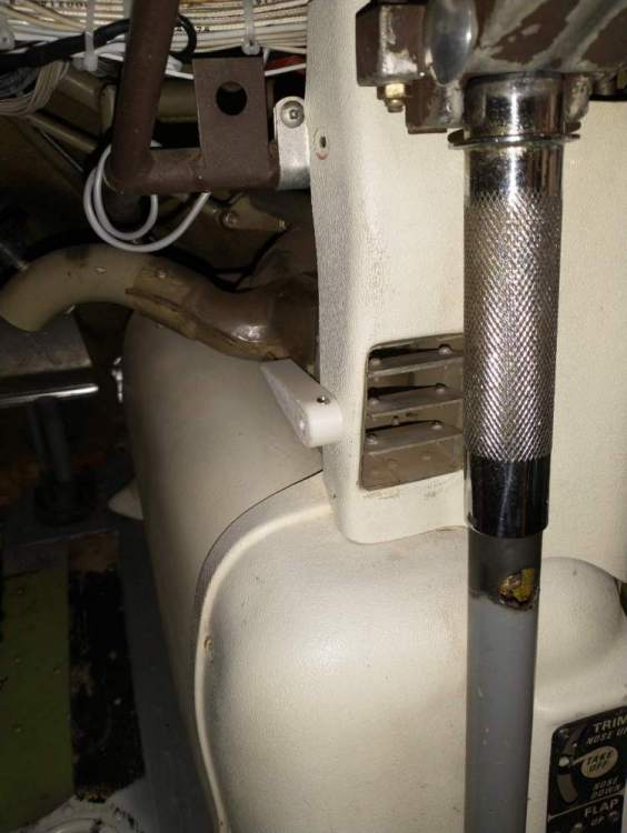
I'm obviously on the slow path to getting my annual done, but I had to send a digital fuel gauge back to Canada to get fixed so the pressure is off for another week or two plus work has been kicking my butt lately. I did complete the 4th vent adapter and paint all of them and then swung by the shop today and did the actual install. See the included picture. Now I need to finish the repairs for the headliner and get that installed. Other than calibrating the CIES fuel senders that's all that left to wrap up the annual. For those wanting vent adapters I am considering producing them for sale. I purchased a 3d printer and am working through the learning curve to see if that may be an option for producing them in a time efficient manner. I'll include a picture with the headliner in when I get that done and give a pirep when I get it in the air.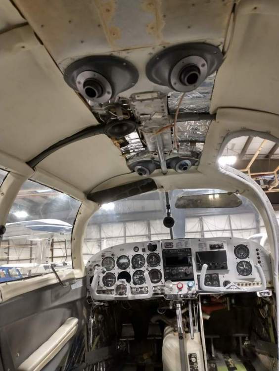
-
Overhead vent upgrade project
Utah20Gflyer replied to Utah20Gflyer's topic in Vintage Mooneys (pre-J models)
Here are 3 of the 4 vents roughed in. Unfortunately I ran out of material and have to wait until more shows up tomorrow to complete the 4th. IA and I agreed on a plan of #4 sheet metal screws for install. I have drilled all the holes for the adapters I have Now I am going to paint the adapters a grey color, countersink the screw holes and should be ready for final install next week. They look like they will be really functional, sitting in the chair I can point the vent at my waist or the top of my head. Exactly what I wanted.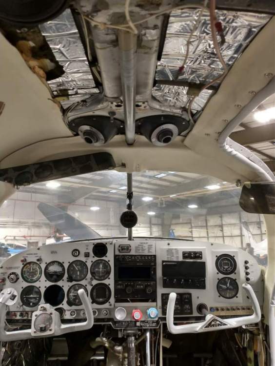
-
J-Model Shoulder Harnesses in an F?
Utah20Gflyer replied to canamex's topic in Vintage Mooneys (pre-J models)
My buckles for both seats are right by the gap between the seats, clamshell buckles facing down toward the Johnson bar, if you brush either with your hand bringing it out of the gap between the two seats the buckle releases. Its a really annoying problem. -
J-Model Shoulder Harnesses in an F?
Utah20Gflyer replied to canamex's topic in Vintage Mooneys (pre-J models)
If you have the Johnson bar then be sure to get push button belts rather than the clam shell style as the latter get bumped and released rather often when putting the gear up or down, at least they do in my plane. That is on my list for a future upgrade to get rid of my clam shell belts. I also have the fixed belts and prefer them, they are much lower profile and I don't find myself being bothered by the lack of give/play in them. -
I heard at one point that they changed the amount of washout in the J wing which made it a little faster, ie an F with all the J mods will never be as fast as a J. Anyone know if this is true?
-
Overhead vent upgrade project
Utah20Gflyer replied to Utah20Gflyer's topic in Vintage Mooneys (pre-J models)
I don't know exactly how the install will go yet but plan to do that later this week. Will likely require a little trimming here and there. The current plan is to Screw the vent to the plenum using #4 sheet metal screws and some sort of seal material between the vent and the plenum. I'll post pics and details when I do it. -
Overhead vent upgrade project
Utah20Gflyer replied to Utah20Gflyer's topic in Vintage Mooneys (pre-J models)
Here is the current prototype set in place. It sits lower than the previous version but don't think it will be in the way. Seems to be just slightly lower than where the plastic headliner will sit that covers the center Frame tube.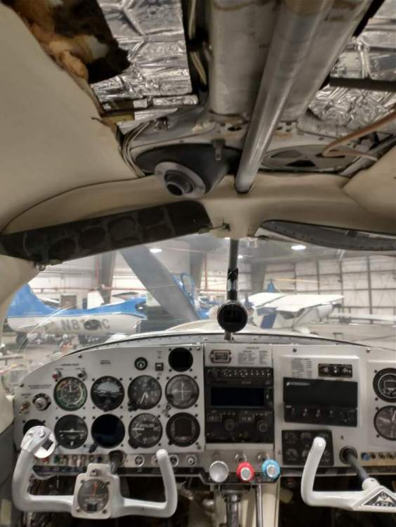
-
Overhead vent upgrade project
Utah20Gflyer replied to Utah20Gflyer's topic in Vintage Mooneys (pre-J models)
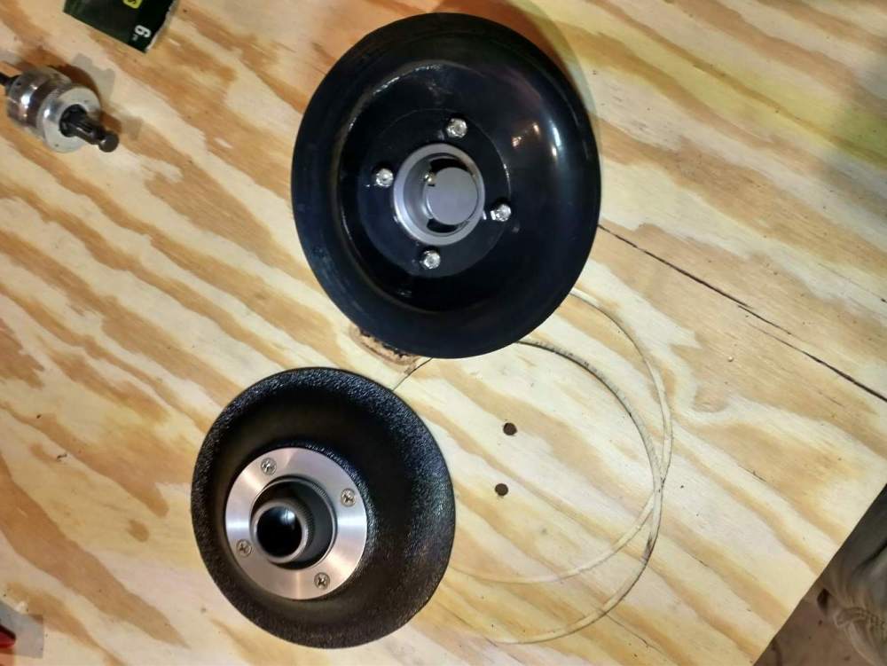
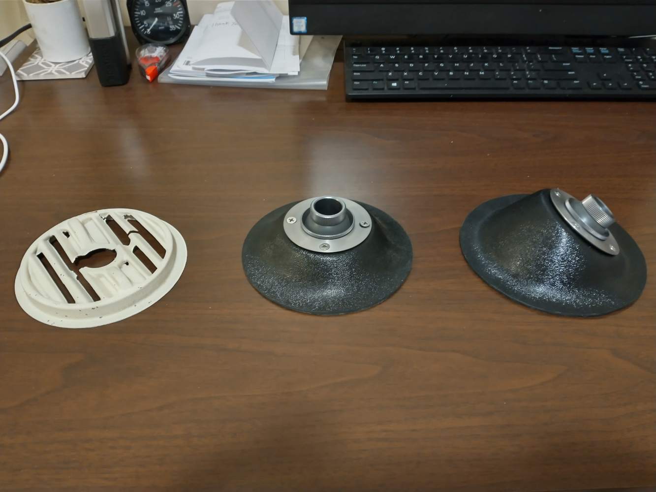
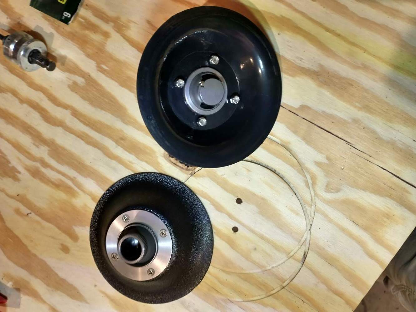
Here is version 2.0, I think this one will fit the mission well. You can point it almost straight down or to within maybe 20 degrees of the ceiling. Also shown left to right is the original vent, Version 1 and then Version 2.
-
Overhead vent upgrade project
Utah20Gflyer replied to Utah20Gflyer's topic in Vintage Mooneys (pre-J models)
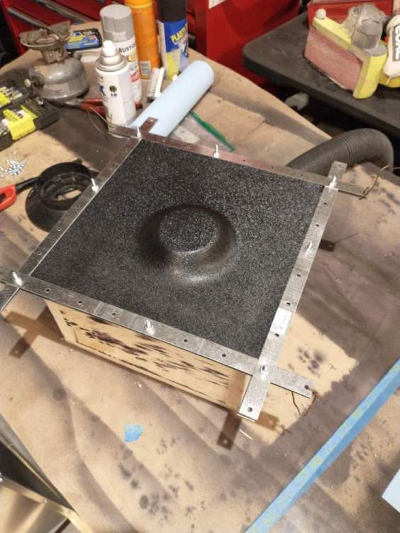
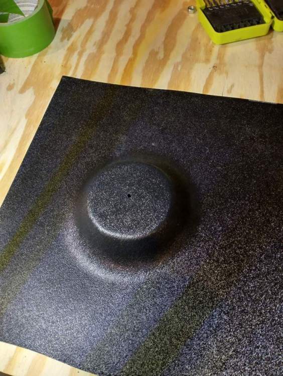
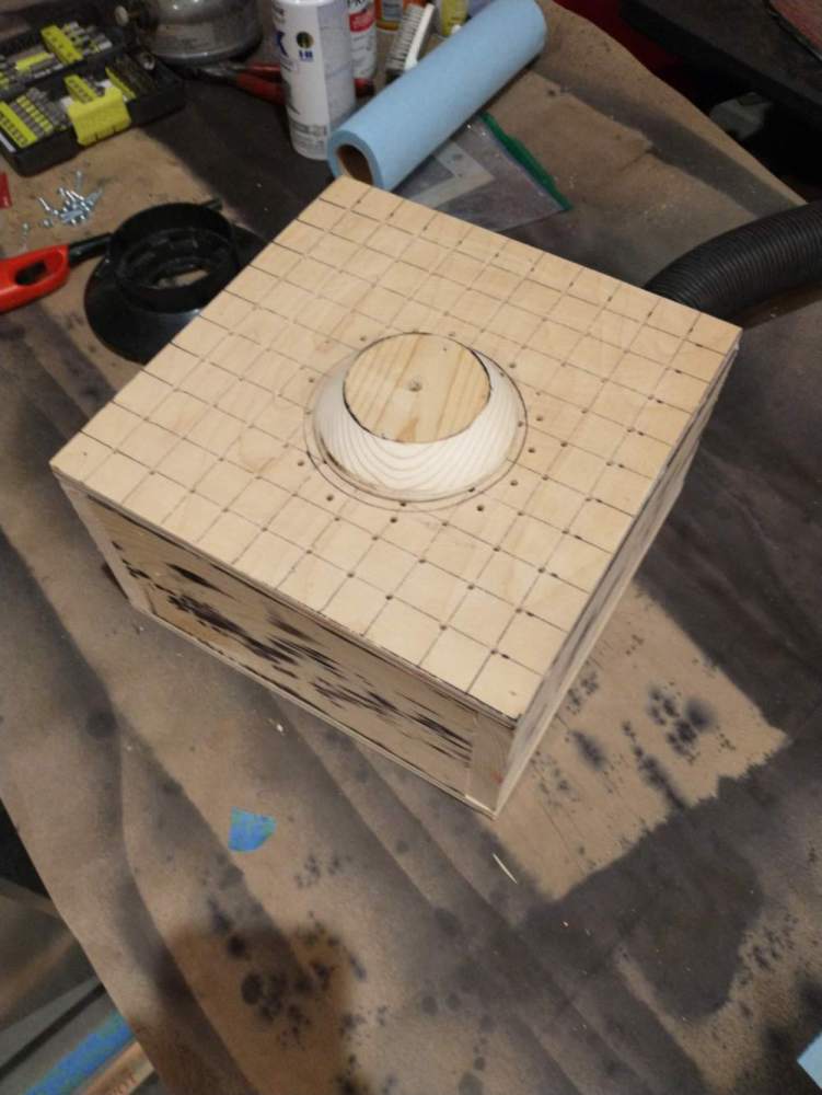
Interestingly the amount of heat has been variable. I have had pieces be ready as low as 240 degrees chamber temperature and as high as 300. Primarily I watch for the material to drop in the holding jig a little more than a inch. I think the variation in temperature has to do with the rate at which I am heating the chamber. Currently I use a propane camp stove for heating and I think I am setting it a little differently each time. The vacuum is being provided by a large shop vac. Like I said I am just using all the stuff I already have, it would be nice to have more vacuum as I cant seem to pull the plastic into sharp corners. My first mold actually had a 90 degree shoulder at the bottom of the mold but it wouldn't pull into it so I adapted the mold to get rid of the sharp angles. -
Overhead vent upgrade project
Utah20Gflyer replied to Utah20Gflyer's topic in Vintage Mooneys (pre-J models)
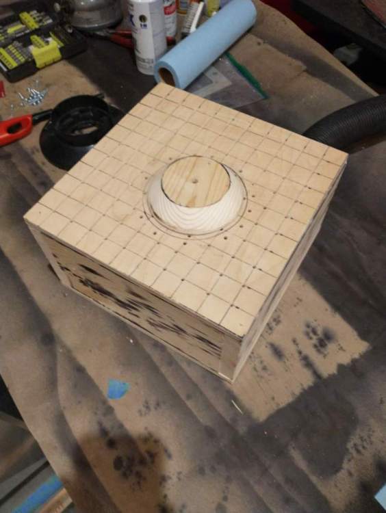
Getting ready to continue the work tomorrow. Here is my blank being glued together to create the next form.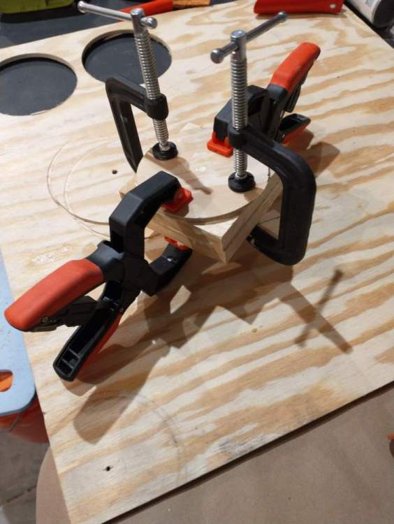
-
Overhead vent upgrade project
Utah20Gflyer replied to Utah20Gflyer's topic in Vintage Mooneys (pre-J models)
The IA looked at what I did so far and was pleased, unfortunately still have to make a new form, hoping to have a new prototype this weekend. -
Overhead vent upgrade project
Utah20Gflyer replied to Utah20Gflyer's topic in Vintage Mooneys (pre-J models)
I considered using fiberglass as I have some experience in that materiel as well but thought getting a good finish would be easier with the abs plastic. I think a female form so I could do a gel coat would be more difficult than a male form for thermoforming. Also once you make the heating chamber, vacuum table and form you can make additional units with much less effort than fiberglass I think. Both are viable and have their pros and cons. Thanks for the input! -
Overhead vent upgrade project
Utah20Gflyer replied to Utah20Gflyer's topic in Vintage Mooneys (pre-J models)
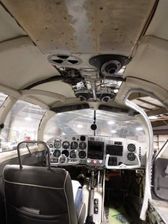
Here is an update, I wedged the parts in where they would go and evaluated whether the vents had enough articulation to hit me in the face - which is where I prefer the air to go when I'm using overhead vents. In the front seats it looks like I could get them to hit me in the chin. The back seats however only the chest. I'm going to consider how to implement N201MKturbo's suggestion and introduce an angle to the part so they can be aimed more effectively. Below is a picture of how they look just setting in place with the current part. Unfortunately I'm just working with the tools a guy in construction would have and not any cnc equipment, so I have to really think through how to make a part that isn't symmetrical. I'm thinking I may screw the mold to another piece of wood so I can cut the bottom in my miter saw, then add more wood to the cut side and reform again with the grinder/flapdisk.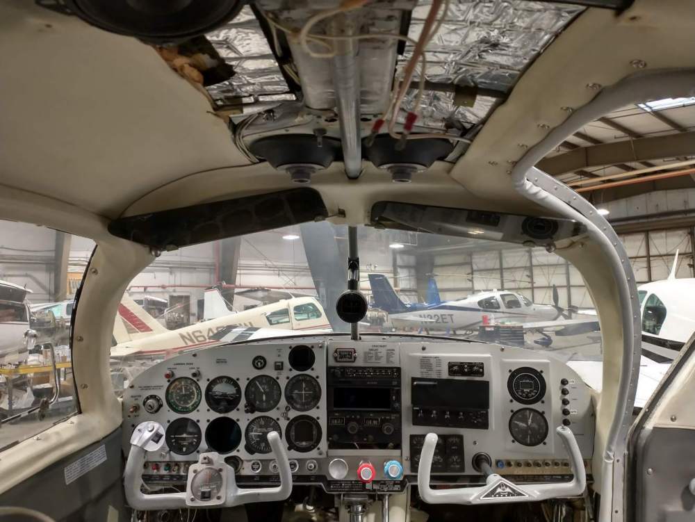
-
Overhead vent upgrade project
Utah20Gflyer replied to Utah20Gflyer's topic in Vintage Mooneys (pre-J models)
Interesting. You may be right. I'll see how they look installed, if there isn't enough play I'll just have to sand down the top of the form at an angle to get the vent pointed in the right direction. The current form is the 4th iteration, so why not a 5th the at this point, haha! I appreciate the feedback! -
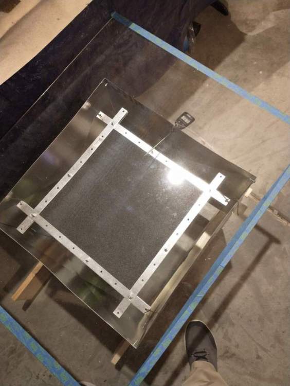
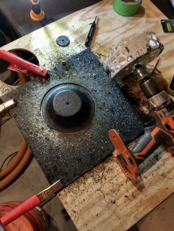
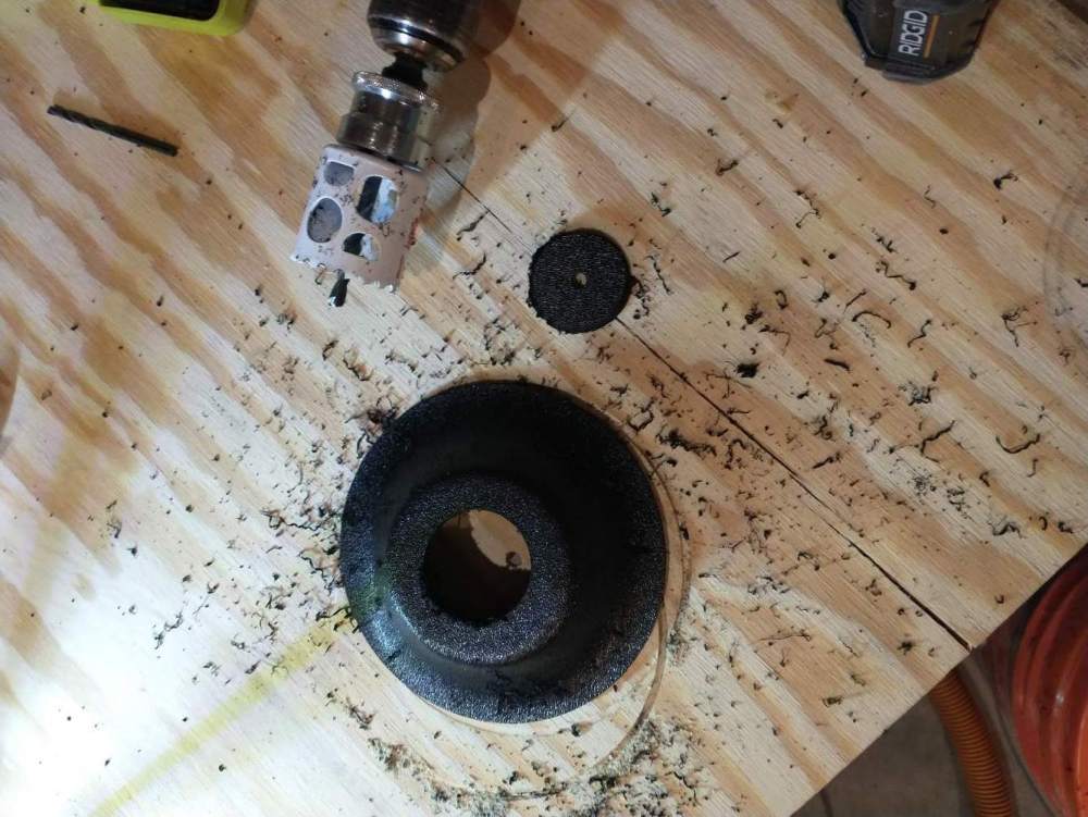
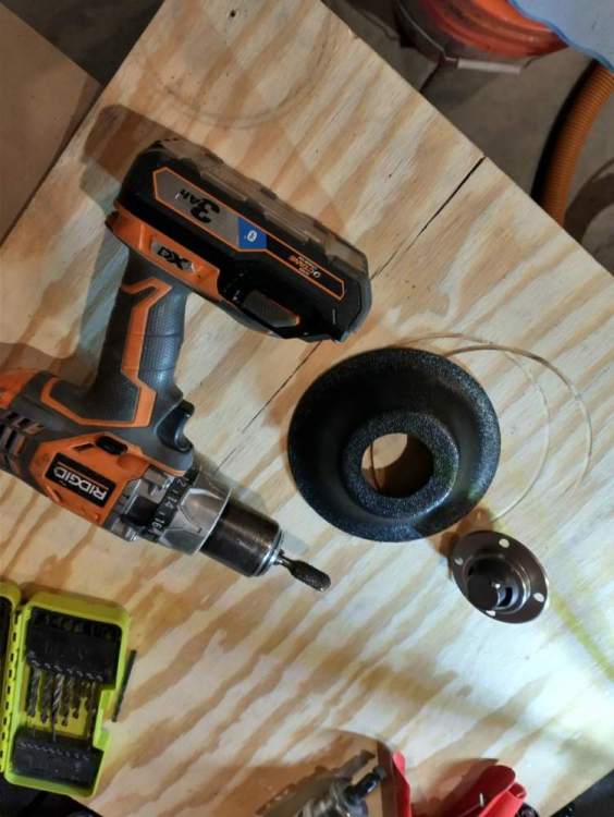
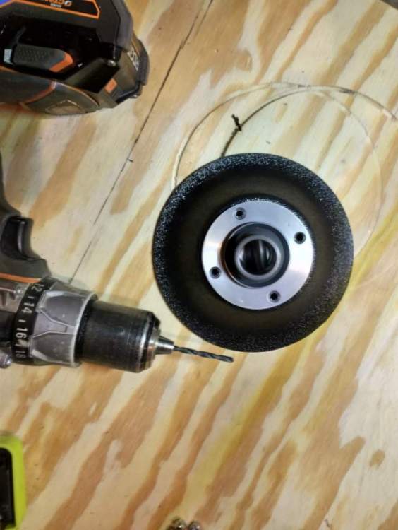
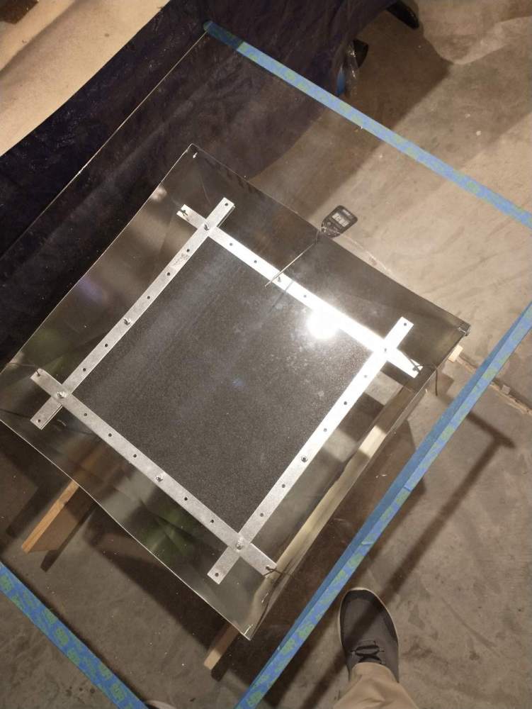
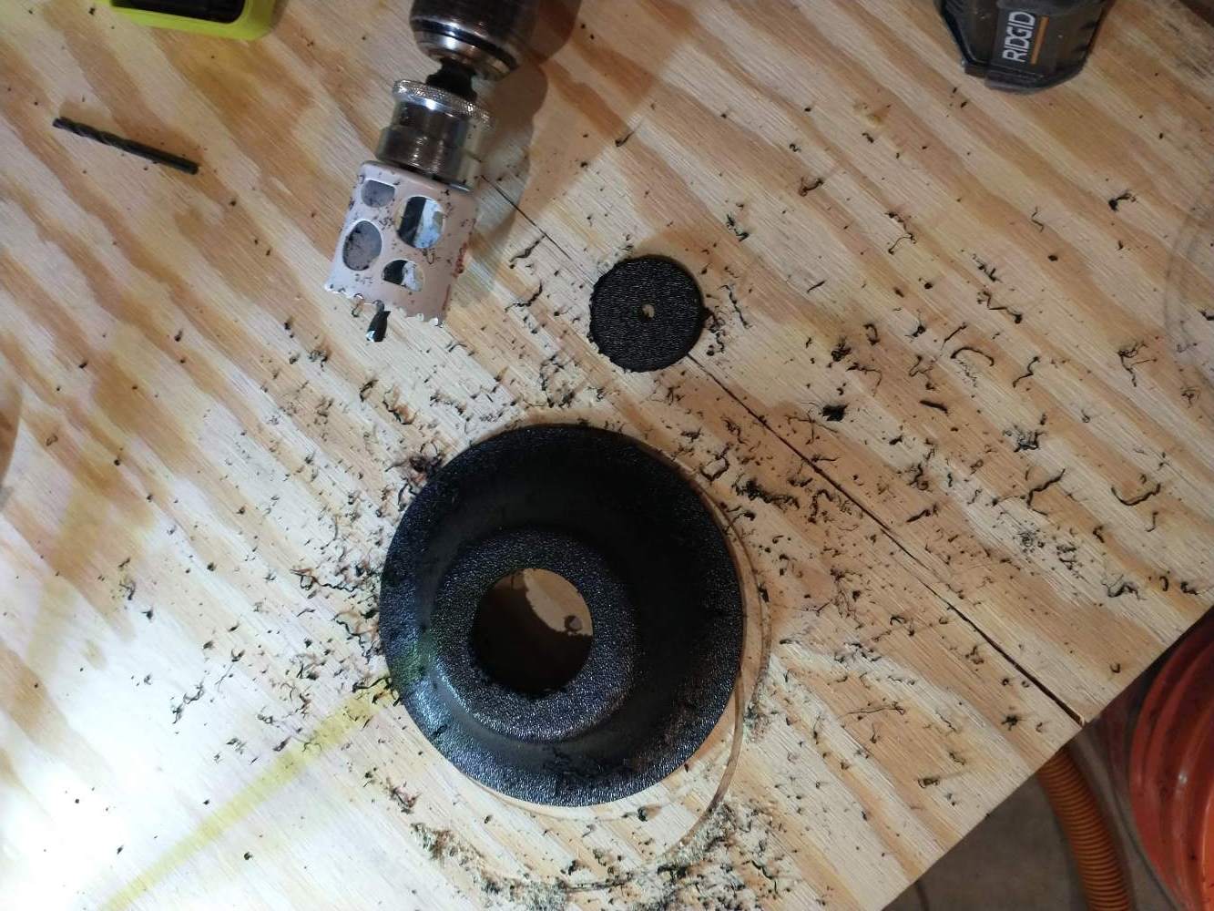
So I am currently in a very extensive annual and decided while the plane was down for a while and torn apart I might as well upgrade my Mooney from the broken plastic overhead vents to some modern eyeball vents. First idea was to order some vents from Wisconsin Aviation. After receiving those I took them in to the AP/IA to see what he thought. Unfortunately he had two conditions 1. They need to come from a company that made the vents for an airplane. They fit this description. 2. I couldn't cut the plenum to install whatever I was going to use....the instructions for the Wisconsin Aviation vents clearly stated you had to cut the plenum to install them, so no go! I had to come up with a plan B. After much thought and research I came up with the idea of thermoforming some adapter pieces out of ABS plastic to space the new vents away from the plenum. I also wanted metal eyeball vents so I ordered some from aircraft spruce. The ones I ended up with are much nicer that the plastic ones from Wisconsin Aviation. Now the hard work. First I had to build a vacuum forming table, a heating chamber, and make the appropriate form to make the parts. I used 1/8" thick ABS which created really strong parts, likely way stronger than they need to be. It took a couple attempts to get the form right and I ruined a bunch of plastic figuring out the correct amount of heat, but with some trial and error I think I got it figured out. I think they turned out well. Tomorrow I will take them in for the IA to review and if they get his blessing I'll work on getting them installed. Here are some pics of the project so far.