Johnny U
-
Posts
28 -
Joined
-
Last visited
Content Type
Profiles
Forums
Blogs
Gallery
Downloads
Events
Store
Everything posted by Johnny U
-
BatteryMINDer 12248-AA-S2 (PRICE REDUCED!)
Johnny U replied to Johnny U's topic in Avionics / Parts Classifieds
Hi dhawkes! This is still available if you are interested. -
BatteryMINDer 12248-AA-S2 (PRICE REDUCED!)
Johnny U replied to Johnny U's topic in Avionics / Parts Classifieds
Hi dhawkes- I am not sure why I am only now just seeing this, but I still have it if you are interested! -
Rear Seat Recline handle 3D files
Johnny U replied to Flyler's topic in Vintage Mooneys (pre-J models)
Wow- you’re not fooling around! Now if we can only start printing out intake ducts to avoid the 35-week wait time from LASAR! -
Rear Seat Recline handle 3D files
Johnny U replied to Flyler's topic in Vintage Mooneys (pre-J models)
We need to learn how to do this as a body… I have played around a little bit with some of the free CAD softwares, but the learning curve is a bit steep. I believe you can create a relatively accurate wireframe model using a camera/photogrammetry and the turn it into a wire frame model/printable *.STL file. Does anyone here have and end-to-end tutorial they could recommend? -
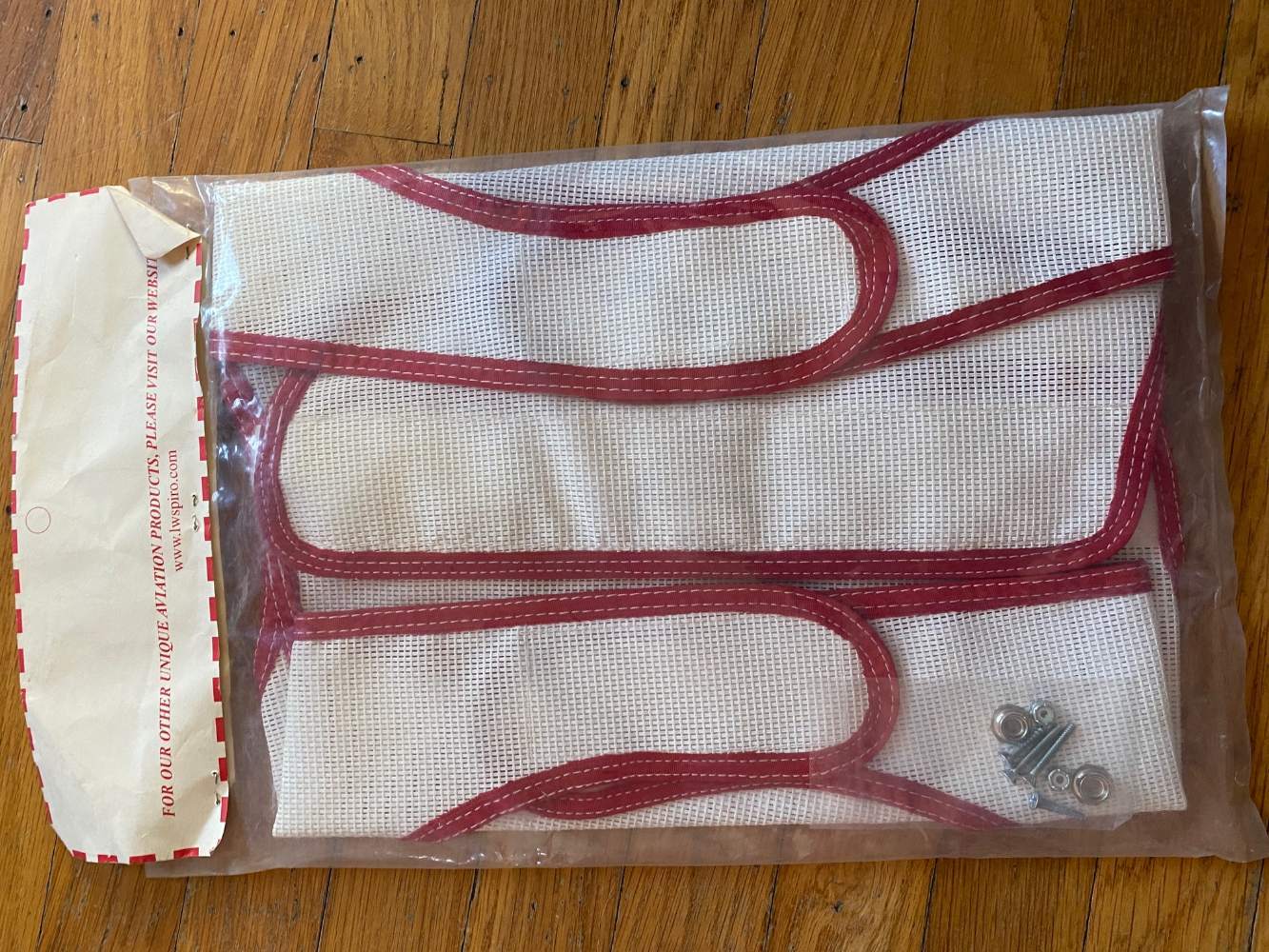
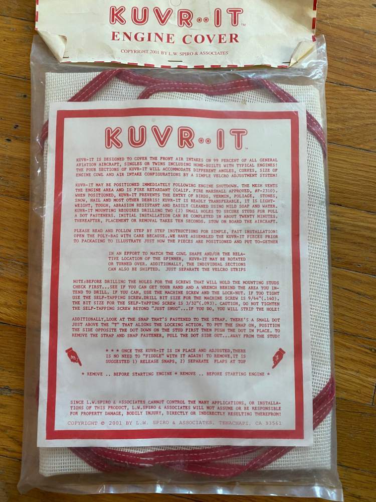
These were a gifted to me many years ago and I never used them. The text on the packaging says it will work on 99% of all GA aircraft (see photo). The company has since gone out of business so I can't give you a lot of detail other than what you see on the packaging. Since N9150V has nose plugs already and I need to get rid of things, I will give it to you for free- just pay for the shipping! Package says it is fire-retardant. It seems to me that the nice thing about this is that it will allow the engine compartment to ventilate more efficiently post-flight since it a mesh fabric...
-
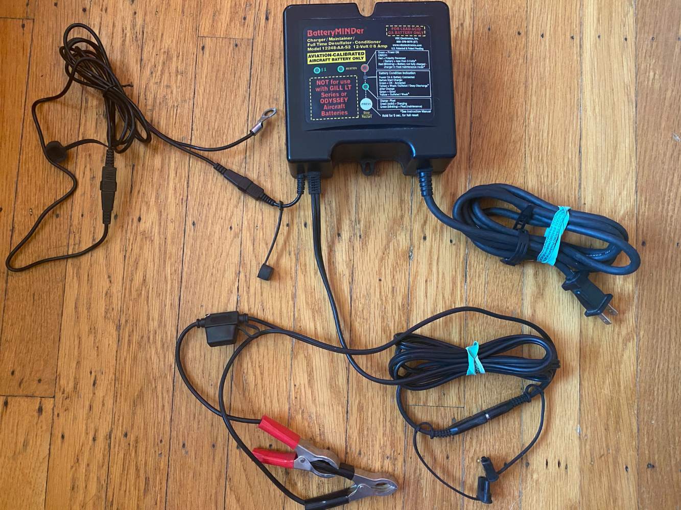
Have a very lightly used 8A BatteryMINDer and in good working order. This model (12248-AA-S2) was designed for charging: Gill (Sealed + Flooded Wet Cell) + Concorde Flooded $150 $120 with shipping here in the US
-
I would echo getting rid of the ADF- you won't ever use it and removing it and the antenna will add a little bit of useful load. I'd say that since you have a pretty functional avionics stack, that you get an engine monitor before anything you start upgrading...
-
Hey Alan- We just need one- sounds like you have a surplus!
-
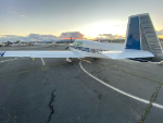
Nice looking flying machine!
-
So an update on the resolution for this- the Deutsch-style crimper that we bought worked well on the Amp II pin connectors. The one issue was the pin depth holder made it such that after crimping when you pulled it back out, the barbs on the AMP II caught (and did their job) and got the pin stuck in the tool. By unscrewing and removing the pin holder- and holding the depth of the pin in the crimper by hand- this issue was resolved. Perhaps a more delicate and precise pin removal after crimping would have avoided this issue in the first place, but at $3 a pop we just removed the depth holder. Either way the crimps were tight and there was no slippage of the wire/pin assembly. In the end we ended up replacing the pin that came loose for the battery relay in order to get power back on and then the other one for the original problem with the NAV light tail circuit. Our A&P took a look before we buttoned it back up and we are now signed off and flying with a new Whelen LED tail strobe/NAV. Thanks to all who helped us figure this out!

-
Thanks Rich!
-
Hi Tom- For posterity I am liking the to the FAA's PDF version of the circular https://www.faa.gov/documentLibrary/media/Advisory_Circular/AC_43.13-1B_w-chg1.pdf . Electrical starts in Chapter 11 on page 11-1 (the 492nd page of the PDF). @A64Pilotmentions Ancor and I bought those for the terminal connections, but I had previously bought these butt splices from Amazon. From the AC (11-167 paragraph b): b. Many types of aircraft splice connectors are available for use when splicing individual wires. Use of a self-insulated splice connector is preferred; however, a non-insulated splice connector may be used provided the splice is covered with plastic sleeving that is secured at both ends. Environmentally sealed splices, that conform to MIL-T-7928, provide a reliable means of splicing in SWAMP areas. However, a non-insulated splice connector may be used, provided the splice is covered with dual wall shrink sleeving of a suitable material. It seems like the last sentence allows flexibility to use non-milspec connectors if they are dual-wall shrinking. Since this is mentioned explicitly in the description of the Amazon item linked to above, I think we are all set on that.
-
I might take you up on this depending on how it goes with the Deutsch style crimper...
-
We recently had the alternator replaced on our 1969 M20F and used the AL12-P70 purchased from Aircraft Spruce.
-
We’ve ordered the Amp type II parts and a crimping tool similar to the above that handles the Deutsch style solid barrel pin. I’ll report back on if it is compatible and creates a quality crimp. Looking at the CAD drawings of both types shows that they are close in dimension but not the same. Johnny
-
Thanks for pointing that out. @N201MKTurbo- The P/N for the plug side of the connector is 201298-1 which takes AMP Type II connectors. Its unclear to me if the crimper you noted above will do that- it lists Deutsch-style connectors. And tools that look analogous also mention Deutsch and Amphenol connectors interchangeably. Is AMP II an equivalent?
-
Does anyone have a recommendation on a crimper that they are happy with in terms of quality? You can find some really cheap ones on Amazon and you can also go to TE and find some that are $500+.
-
That is really good to know!
-
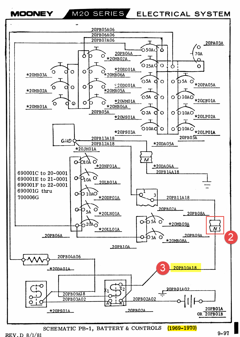
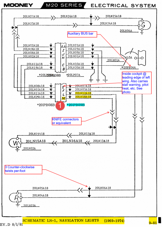
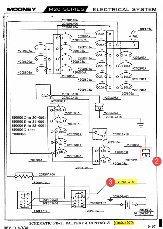
Hi all, Note/Edit: After seeing @carusoam's post below, I just wanted to clarify that we are working with an A&P on this project and so we need everything done up to a quality that he will sign off on... We are the (two) new owners of a 1969 M20F (N9150V) which we bought in December from @Stephen after we found his posting here on Mooney Space and after @Culver LFA ferried it from MO to Oakland, CA. Its a nice flying machine, but like anything that age it has a few things we need to deal with. Right now we are working on a tail nav/strobe replacement and could use a little advice both on resolving the initial problem and then the problem we created when started "fixing" things. Issue 1: Tail NAV light is out, plastic is damaged. Initial diagnosis: Light assembly is old, maybe has water damage and has failed. Solution: Replace it with a Whelen Orion 500v. Result: Strobe works, NAV light still not working. Debugging1: The voltage on the strobe is ~12v and the NAV light works on this as expected. The voltage on the NAV circuit is sometimes 9.5 or maybe 11.5 or maybe 8, but always varying moment to moment. When connecting the NAV light to the NAV circuit the votage drops from whatever voltage it was showing down to 1 or 1.5v. Analysis: OK so we should have done this test before buying a replacement light(!). I looked at the filament in the incandescent bulb and verified it was not broken and so I *assumed* that the internal electronics had failed and did not consider or fully test the circuit itself. Debugging2: So initial troubleshooting shortcomings aside, we were able to determine that something was going on on the positive side of the circuit and and started to dig into the NAV light schematics in the maintenance manual (page 9-81 image below) to start breaking it down into bite size chunks. We already had verified that there was no continuity and extremely high resistance from the NAV light switch to the tail. So the first chunk was to test from the tail to the first connection (#1 in "Schematic LN-1" screenshot below) where we verified continuity and measured very low resistance. We noted a little bit of corrosion in the pins (#5 in photo below) and sprayed it with electrical connector cleaner and wiped the mail connectors as best we could. So first section was tested good, from the plug (male) connectors to the tail cone... Then umm... wait a minute, why is that dangling wire there? Wait, why is the master switch no longer turning the power on? OK, we can no longer work on issue #1 because we need to address the problem we just created which is... Issue2: Total electrical power loss/master switch no longer turns on power. Analysis: Dangling wire labeled "20PB10A18" (#3 in schematic below, #6 in photo below)) was connected to "N" hole in receptacle (#2 in schematic PB-1 below) became brittle and broke off when we disconnected (and wiggled and moved around) plug 20-PB09B (#5 in first photo below) from receptacle 20-PB08B (#4 in 1st photo below). (Would be) Resolution: Remove pin with jury rigged extractor and replace it with um, a thing um size um... and this is where we get stuck... Questions related to issue #2: What size pin is this and where does one go to find a replacement? I am sure if I had the size I could find it, but a supplier name could be helpful. Also, these were crimped rather than soldered which surprised me- thoughts on the replacement? If the wire seems to be too brittle over more than just the last quarter inch when we strip it back, should we consider replacing the length? If so what is appropriate wire/part number for that? How do we go about labeling it for posterity? Now that that is settled and power will soon be restored we can get back to the original issue... Meandering Thoughts and Questions related to issue #1: Having isolated and confirmed continuity downstream of the plug, the problem is either the contacts within the plug/receptacle assembly of upstream to the switch. Left and right NAV/strobes are fine and both go through that connection. Access to the second "flight panel" plug/receptacle (Schematic 1- 20LP06A/20LP07A respectively) is pretty onerous. In fact, while I can see up into the rats nest of wires behind the panel that there are a couple of candidate connectors, it is unclear which is which and how one would go about disconnecting them- there just is not any real access or good visibility. Maybe I am looking in the wrong place. To bypass access issues and having to dig the hole we are in even deeper, would it be a legal approach to go straight from the NAV switch, which is accessible, and put in a new wire that goes directly from there to the receptacle side of #1 in the upper schematic- in other words when re-wiring something does it need to be replace a like with a like? And regardless of legality, would it be unwise to that? I can't see anything about that that would be unsafe and that would make it a much more painless speedy fix. And are there better (AMP?) connectors that the black plastic ones- should we consider replacing the assembly now that we have it out- that seems like if might be more trouble than its worth, but would not want to waste the opportunity if it should be done... One step forward, two steps back... Any advice on how to proceed? Johnny


-
What is the weight of a J seat? Or where do I go to find that information?
-
Can you provide contact details/URLs to get to Alan?
-
'69 M20F Service and Parts Manuals, please????
Johnny U replied to CrazyWilly's topic in Vintage Mooneys (pre-J models)
I am all set @carusoam! Thanks! -
'69 M20F Service and Parts Manuals, please????
Johnny U replied to CrazyWilly's topic in Vintage Mooneys (pre-J models)
An about to be Mooney owner needs a parts manual! Looked in the downloads section, but I don't think it's there. This would be for a 1969 F model and if someone could send me a copy- I can be found at jurness@gmail.com or if you have a google drive link you could paste it here... or pm me or email me. Anyway that works! Just trying to learn as much as I can before taking delivery in the next couple of weeks... Thanks in advance! Johnny -
Any one know anything about this paint shop near TPA?
Johnny U replied to Mooneymite's topic in General Mooney Talk
Seems awfully cheap... Might be too good to be true. -
Ferry Pilot Needed for M20F from KHAE to KOAK
Johnny U replied to Johnny U's topic in General Mooney Talk
I've gotten several PMs (including Frank) and have been trying to respond as quickly as possible- this has turned out to be fertile ground and I am feeling very appreciative of the time people have taken to respond or make proposals.