jamesm
-
Posts
877 -
Joined
-
Last visited
1 Follower

jamesm's Achievements
")


-
Engine doghouse #4 tinnerman speednut
jamesm replied to Hradec's topic in Vintage Mooneys (pre-J models)
I was annoyed with those tinnerman nut / speed nuts / clip nuts or what ever they are called. and re-did the whole engine baffling with #6 nut plates so I don't have to change screwdriver tip sizes #1 and #2. edge margin maybe questionable but the machine screws is less likely work it self loose and plus they have more of a bite than sheet metal screws Tinnerman/speed nut apparatus could ever give. tried of fishing out the lose Tinnerman/speed nut would work them self loose or missing. -
This is what I found so far I could be a stretch but according to Mooney's Parts catalog that I have (see attached for photos as well) calls for AN6270-2-35 (#30 Part Cat). I am assuming ... -35 is length in inches and -2 is diameter of the hose. Application: Air or vacuum instrument systems, automatic pilots, and lines to pressure gauges used with these systems as specified in MS33620. Hose assemblies conform to AN6270. Hose conforms to MIL-DTL-5593. Fittings conform to MIL-DTL-38726 and MS27404. Supersedes AN773 For 306 am I missing something? I know the Eaton 306 vacuum and pressure lines but since Mooney calls it out in there Parts catalog does make valid to use 306 Hose? Thanks again for all the input and sorry for beating a dead horse over and over. I needed a reality check. James '67C carb_pressure_line.pdf
-
How do I deal with fitting coming off the carburetor for fuel pressure line? it's a -2 flare 90 degree looks to be a aluminum ( blue) fitting. The current installation doesn't go through the firewall. it has a ~ 25" long -2 hose going into an EI CGR30C/P pressure transducer which of course has a male fitting to a -2 hose flare fitting. mounted on one of Engine mount tubes. Can the carburetor fitting be aluminum? same with the EI transducer should be steel or aluminum or ??? Thanks for all the input. James '67C
-
Yes if I recall correctly that the original fuel pressure/ manifold pressure gauge, used a -2 fittings on gauge and the firewall fittings to respective sources. The manifold pressure gauge used an aluminum line (right/ wrong or indifferent) at least since the time the plane has been in the family since 1984.
-
Here is what I found… https://aircrafthosestore.com/pages/how-to-choose-an-aircraft-hose as expected no -2 hose are made for fuel pressure line from carburetor to fuel pressure gauge. I tried to find it in the Mooney maintenance manual and IPC. No luck
-
I can't find it for such a small diameter.
-
I am having a discussion with another A&P & IA about hoses. Had fuel pressure line from carburetor to fuel pressure transducer on the engine monitor CGR30 which is -2 diameter hose. it a -2 at carb and it's a -2 at the pressure transducer. the hose started spraying to confirm it really was the hose, we removed it plugged one end and blew air soapy water and watched the soap bubble. I have been down road a gazillion times but found no real definitive answer. both the manifold pressure line and fuel pressure line off the carburetor has -2 fittings. problem is that the so called fuel rated hose material doesn't really start until you get to -3 diameter and larger diameters. If you use Aluminum line it work hardens I have happen to me twice. IMHO it would be stupid to run fuel through in such a small of diameter which would break frequent . I suppose you put couplers and reducers and enlargers and you would have about 1/2 foot of fittings pron to leak. Maybe it's done out in field but I would suspect I would seen it all people 's pictures of their plane photos. If I look at Parker page the 193 hose is for vacuum and air on Mcfarlane web site. I have found plenty of Hose material compatible of supporting Fuel and Oil by haven't found one that supports that is -2 diameter hose diameter. . What Guidance do I have or where would I go to find -2 diameter hose material that supports "Fuel". Please advise, James '67C
-
This video For Reference and demonstration and informational purposes only. seek someone who has done this adjustment before. I have never had to make any adjustment to the gear in 40 years the M20C airplane been in the family. It's one job you don't guess at or tackle without foreknowledge and experience.
-
Interior firewall insulation replacement
jamesm replied to Matthew P's topic in Vintage Mooneys (pre-J models)
I have done many years ago when I had the engine overhauled it silver flame resistance material it met part 25 requirements and burn papers that came with it. The finish component looked ok (wasn't that great), fast forward say 12 years or so, let just say my feet have no grace so the top foot well on the cabin side looks like hell now. When the firewall still on the plane there is no way to feed the insulation material under truss and structure of the airframe, it can't really be done at least if there is a way I couldn't tell you. Like Rich said to do right, you would have to completely disassemble the firewall. which to me looks like no easy task. James '67C -
I just wish that the G5 had bigger cursor or unique identifying feature on cursor making it sticking out easier to see and bigger font.
-
I have tried hitting the photo cell with bright light and see if brightens ? it could be that driver or components has out lived life expectancy.
-
Better yoke mounted PTT - 3D Print
jamesm replied to Twing207's topic in Vintage Mooneys (pre-J models)
is it held on by tension? here is my cheap attempt to do a similar thing less creative by using aluminum angle and a hose clamp. an older picture.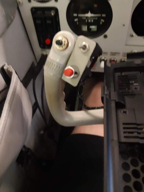
-
Weight and Balance graph profiles
jamesm replied to jamesm's topic in Vintage Mooneys (pre-J models)
Thanks I sort see the error in my ways. Mooney Graph shows 14.5 across bottom X axis and about 6.5 across top X axis. while other application like other People's Mooney's Excel formula and Foreflight shows 7.0 across bottom X axis and about 2.5 across top X axis. Sorry about I guess I need to stare a bit longer to figure it out. Thanks, -
Weight and Balance graph profiles
jamesm replied to jamesm's topic in Vintage Mooneys (pre-J models)
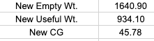
my math seems a little wonky. if new CG of the ~45" plus the graph Foreflight or other People's Mooney' of the same body/model. I can't grasp the why the shapes are so different. -
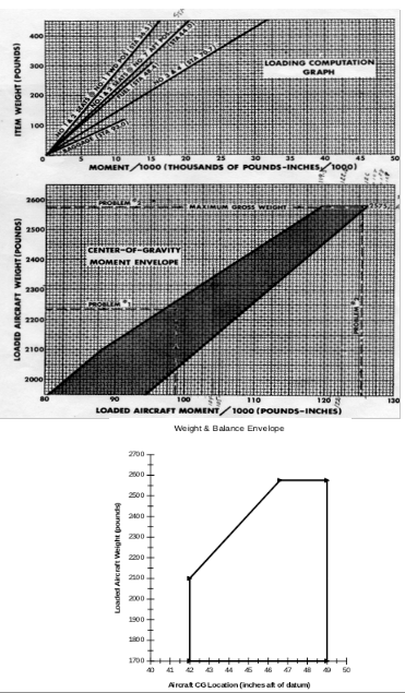
I suppose I should know the answer to this but for the life of me it does not compute. So the Weight and Balance Document that came with the 1967 M20C Mooney aircraft. Shows two graphs "Item weight" versus "moment" and "Loaded aircraft weight" versus "moment". The Weight and Balance Document that came with the airplane gives a couple of sample problems given by Mooney. The Chart /graph shows about 80 and goes to about 126 and is in /1000 Lbs-Inches on the X axis. when plotted/graphed out it looks a fallen trapezoid. While the other documentation for other people's Mooney's and applications like Foreflight starts at 40 ish moment and the plot/graph looks like rectangle missing the upper left corner. also all the Weight Balance records starts around 40 ish go to about 49 inches . My questions are: How would you describe the difference to a DPE if you were going for a check ride. If they ask why does one look like graphs look so different. one being a fallen trapezoid narrow at the top while the other looks like rectangle lobbed of corner? As far as I can tell both charts/graphs appear to both be linear may be distorted in the cut and paste process. I really don't have good answer to these discrepancies or perceived discrepancies. I am assuming the Item weight charts starts zero which I believe zero Datum the goes around the center line of the nose gear truss. so that might explain why one start chart/graph starts 80. but my math doesn't seem quite work out. what I can't explain the difference in shapes between the plotted Mooney and other people's Mooney's and applications like Foreflight. Thanks in Advance, James '67C