

ronr
-
Posts
37 -
Joined
-
Last visited
Content Type
Profiles
Forums
Blogs
Gallery
Downloads
Events
Store
Everything posted by ronr
-
Infinity is good and services many small GA aircraft. Leland Aeroservices is also on the field and has been servicing my Mooney (and many others) for many years. They are also busy but John Leland is very knowledgeable as are the other IA/AP's that work for him there.
-
I've had it happen twice. Once at an FBO / radio shop about 40 years ago. I found it after they had moved it and they picked up the tab for my shop to fix it. I happened again a year or two ago. I have no idea how it happened as it did not "appear" that the aircraft had been moved, and I did not check it after it had been parked on the ramp at a particular airport, but a later inspection done because the steering felt squirrely on the ground revealed that the truss was severely bent and cracked. Insurance paid for that one.
-
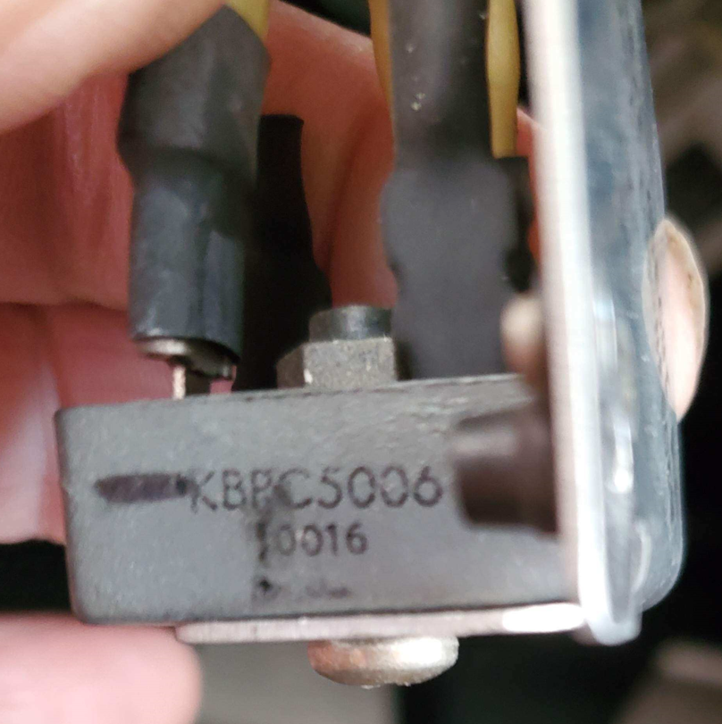
@N201MKTurbo I don't think you can do that. Internally there are four diodes connected in a ring. But it would interesting to measure the voltage output on the other terminals. Unfortunately, I don't have that information.
-
If, when the actual part, not just the bracket, is visualized, it looks like: Then this is my guess -- a part of the standby alternator install:
-
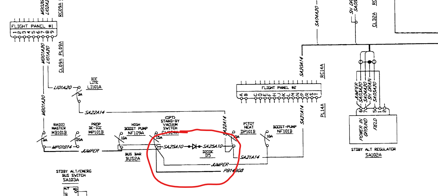
Old thread but I just discovered the possible answer troubleshooting a pitot heat failure in my Ovation. If yours is the same as mine (and your picture has disappeared, that part is a diode (actually a rectifier used as a diode) and is part of the stand-by alternator install. It ensures that circuits not on the "essentials bus" are unpowered during use of the stand-by alternator. It shows up as Diode D5 on the schematic for the stand-by alternator install. There are several of them added for that purpose in various places.
-
That was something we actually considered for a short time. Once we reviewed all the schematics (especially those for the stand-by alternator install), the log books and the specs for the KBPC5006, that clearly could not be the case.
-
In a PM from @StevenL757 to me, he mentioned that the item is used as blocking diode for the standby alternator system. It prevents the non-essential bus from being fed by the standby alternator. The schematic for this installation was not available to me in the documentation I had from Mooney, but I was eventually able to locate a schematic for my Ovation serial number. It seems that when running the standby alternator, this diode will block power to adjacent switches to the left of the Pitot Heat breaker switch, none of which are on the essential bus. But under battery power, there should not be any drop in voltage across this diode. Since we measured a significant drop, my assumption is that this diode has failed. A replacement is on order. Thanks to all. Ron
-
That does not explain the absence of increased current draw when testing this on the ground (which has been present for the five years I have owned this a/c on every pre-flight). There is also no mention of this being a requirement in the AFM or in the TKS supplement of this being a requirement for the routine pre-flight testing of the pitot heat. And where is that pre-flight testing procedure documented?
-
I will do that Monday. But I've got the Install manual and diagrams for the TKS system from CAV, and, although it mentions replacing the pitot heat breaker switch with a different one, there is nothing on that diagram indicating that the power to that switch is anything other than a line from the 28 V bus. No sign of any rectifier, diode or anything else in that line.
-
Thanks, Rich. Yes, I know what it is. And your link is arguably the least expensive. But my question is really if the diagrams I have are just lacking that item? Or if it was put in for some other reason. I don't have my logbooks handy so can't refer to them.
-
2003 M20R DX 29-0289 (28V system) with factory installed TKS FIKI system. Yesterday I turned on Pitot heat and the current draw, which usually increases from about -2A to -9A did not budge at all. Troubleshooting today, we found 11.9V at the input to the Pitot Heat Breaker Switch (unexpected in a 28V system) which dropped to 70-80 mv when the switch was turned on. In the line going to the hot side of the Pitot Heat Breaker Switch, we found a "box" which I could not locate on any of the diagrams I have. This appears to be a rectifier according to the part number and appearance. The voltages read about 23.9 V in and 11.7 V out, so it appears to be faulty. But I can't locate this item in the various maintenance manuals I have, nor does it appear on the electrical diagrams I have access to. I'm guessing it is there to block spikes when turning off the pitot heat switch. Is it a standard Mooney part costing hundreds of dollars? Or something I can buy on line (I've seen them for under $5)? Thanks. Ron

-
@carusoam I've looked at that data. And there are no clues on the voltage readout. It is rock steady at 27.7 volts until there is a sudden drop to 23.2V when the breaker pops. Probably a 2 second interval is too long to capture any fluctuations. And that's the minimum interval on my JPI.
-
@carusoam Finally a probable solution. It wasn't a bad field diode; it was a completely absent field diode! Diagnosed by DMax via email, by the way. Reviewing the logs, the previous owner had replaced the stock Continental alternator with a Plane Power unit. A few months later, the ACU was sent out for "repair". I have no idea the reason for the repair, and the shop where it was done did not have access to the work order. My guess is that the diode was removed with the swap and maybe the ACU was sent out for the FB popping, but that is only a guess. The diode was added. The very next landing the FB popped and the idiot light on the annunciator panel showed that it was due to overvoltage. I had never checked regarding over/under voltage before that time and thought that `o..sh` it didn't work. But the next six landings have all been OK with no further popping of the field breaker. So, hopefully, the good behavior will continue.
-
I look forward to it. First one hr flight today with new engine. Everything seemed nominal except idle speed too high. But that'll be adjusted when they uncowl for the post flight inspection. Seems to be running well. And I'll be looking at the download from my JPI later on.
-
I think in older airplanes, that have mods done over the years, certain things (old cables, conduits, etc) may not get removed, and contribute to inaccuracies in the calculations.
-
I weighed a previous Mooney (an M20E) once, about 30 or so years after it came out of the factory. We did it because my IA just got a set of scales and wanted to try them out. I lost about 70-80 lbs useful load! Hence my reluctance.
-
@StevenL757 or @carusoam Overhauled engine/prop etc finally back and being re-installed. It has the N cylinders. Neither I nor my IA have been able to locate online guidance regarding weight and balance computation. From what I've read, the N is either 18 or 18.3 lbs lighter than then G, but I haven't found anything official about re-computing the W&B when modifying an Ovation with this change. What did you all do? Thanks. Ron
-
The overhaul facility felt that he hadn't seen any more cracks in N vs G cylinders. The Heads are the same. So I've not been too concerned about that. He also thought that he had heard that with less weight on the nose there would be a speed increase. Kind of makes sense theoretically as, with the cg further aft, less down-force needed on the elevator which should equate to less drag. (Whether it is significant or not is beyond me to calculate). Thanks for your thoughts. Ron
-
Steve, Thanks for that. In doing some more research I also note that there has been a change in STC SA02193CH. The STC with my paperwork is ONLY for the installation of the 3-Blade Hartzell prop on the engine. The current STC verbiage is and, instead of being just for the prop install, is described as being for a power increase by virtue of installation of the prop and either a modified io550G or an IO550N. I guess that plus the continental SB pretty well nails down the legality. Ron
-
I am about to have my IO550G-AP (310 HP modification from Midwest) overhauled. Replacing the G cylinders with N cylinders has been recommended (and makes sense to me given the lighter weight and consequent moving of the CG a bit more aft). Also recommended by the overhaul shop, who indicates he had done a number of these in the past. But reading through the verbiage of the engine and propeller STC's, I don't see where that is an allowed modification. The Propeller STC clearly states that it (the Propeller STC) is valid for either a G or an N engine, but I can't seem to locate anything that directly allows the replacement with N cylinders. And the TCDS calls for one of several IO550G's. What am I missing? Thanks
-
@carusoam Thanks for the heads up. I've never had a problem when cycling the alternator switch. And that gets done frequently as it is a step during the pre-flight check of the backup alternator. I'll mention it to my mechanic. But I'm thinking that if it is not due to a strangely placed wire that only shorts out in a particular airframe configuration, that there's probably an issue with the voltage regulator.
-
@PT20J Yes. If there's nothing in the wiring, I suppose sending it out for testing would be the next step. Seems like no one (including my mechanic) has seen this precise scenario before. Doing an overhaul this summer (when our airport at KEPM will be closed), so that would be a good time to check that. @carusoam So far, the only way I've been able to reproduce the event is in the landing configuration with throttle all the way back. And tracing all the wiring requires dropping the lower cowl.
-
@PT20J The only times I've brought the throttle to idle have been on landing and before shutdown. I've not done that immediately after a run-up. I'll give it a try the next time I go out to fly. So far as the overvoltage protection circuitry, I believe it will pop the field breaker. But it seems unlikely that the voltage would surge at low RPM. It doesn't show up on my JPI memory dump, but that is at 2 second intervals so could be easily missed.
-
@EricJ I'll have to take a look at the meter the next time it pops. And it does seem that it is more likely to pop the more load I have on it. But I've landed plenty of times day VFR with it still popping, and occasional instances when it has not. With "everything" on (lights, pitot heat, TKS), however, it's always popped -- but only during rollout. If I taxi to the ramp; then put throttle full aft and idle at 650 or so rpm; and turn everything on -- no popping. @rgpilot Doesn't pop on shutdown; only during landing rollout with low rpm.
-
Thanks. Pulling the wire will probably be the next step, but note that mine does not pop with the engine off -- only during the rollout after landing.

