FlyBoyM20J
-
Posts
184 -
Joined
-
Last visited
Content Type
Profiles
Forums
Blogs
Gallery
Downloads
Media Demo
Events
Everything posted by FlyBoyM20J
-
I see...well, I ordered the clamp-on kind just b/c it looked easy to install but I'll see if I can cancel it now. This kind looks like it needs to be spot-welded on...or do you clamp it through those loops?
-
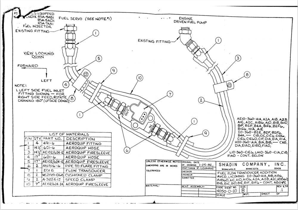
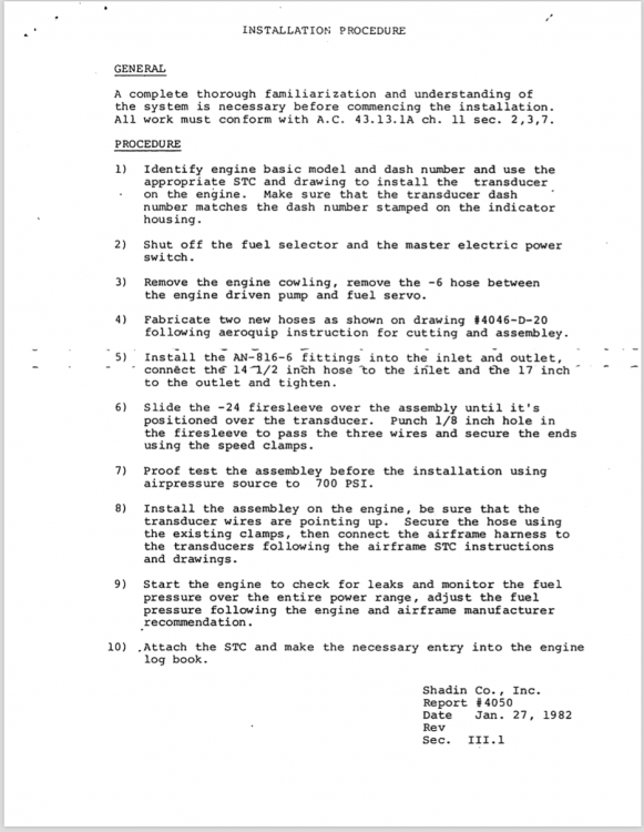
I went through all the paperwork that I received from the previous owner and I found the Shadin STCs, install instructions, and drawings. Here are the relevant diagram and instructions. It looks like Jetdriven's install is 100% per the manual. I suspect that mine was done right originally but when the engine was replaced, someone just did what appeared to make sense when putting it all back together. I wish I could be certain that the hose length between the FF transducer and the servo is 17". I'd just have Spruce fabricate a new set, get some new AN816-6 fittings to eliminate the 45-degree on the inlet, and get this looking nice. I suppose if I'm going to that kind of trouble, I'd replace the transducer, too. This one has been cooked long enough. Can anyone confirm these dimensions on an A3B6D? Cliff
-
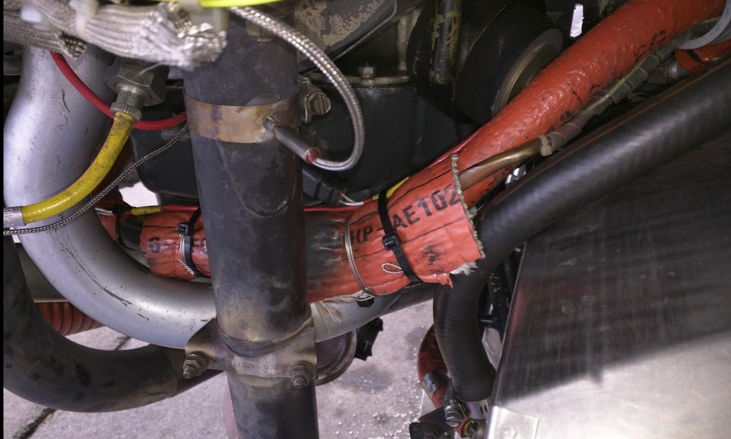
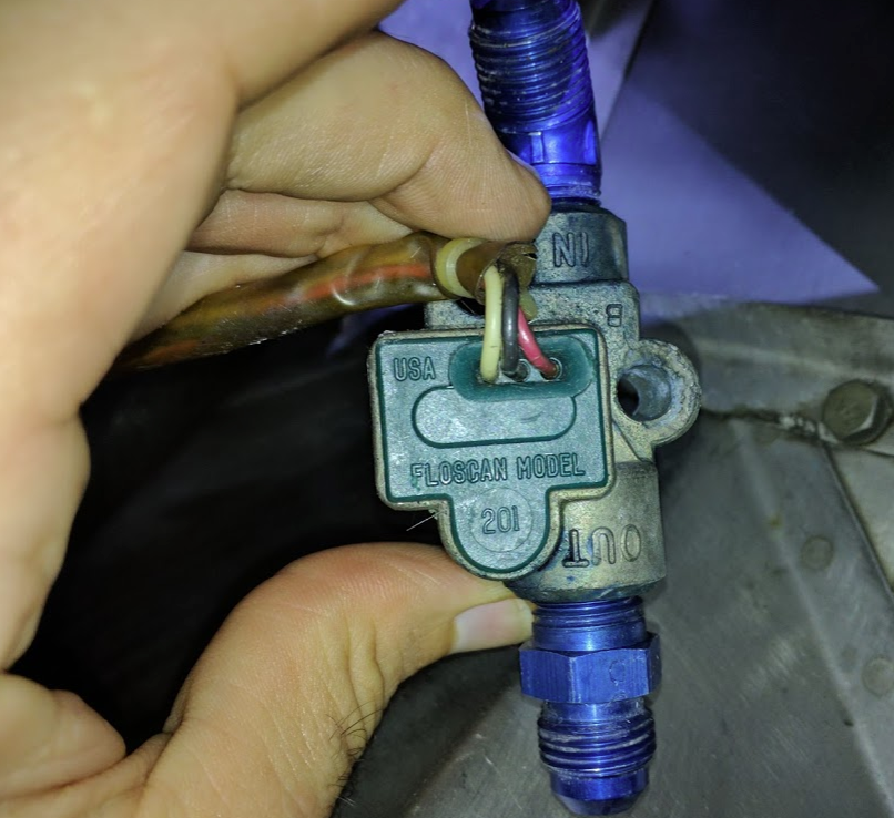
OR75 is correct - I looked at what it would take to move the FF transducer closer to the sump and lower down on the intake tubes. It seems that the fuel hose connecting the output of the FF transducer to the servo is simply too long. I was able to add some Adel clamps and get about 3/4" of clearance from the C4 riser but I would like to get this done properly. These are all nice, certified fire hoses but I think I'd be more comfortable replacing them. If I can make out the "Cure Date" on the metal band on the hose that that is so long it's forcing the FF transducer towards the exhaust, I believe it is 2004. The hose on the other side going to the FP transducer has been resting on the C1 intake tube forever and has a dent in the fireproof material at that point. I think something else should be done there, too. Anyone have a picture of how that side of things should be done, too? @jetdriven I see that you have posted about 124J hoses a lot over time and I'll start by researching what you've written already. And when you suggest a heat shield, are you talking about one of these? https://www.aircraftspruce.com/catalog/eppages/clamponHeatShield.php Thanks, Cliff
-
I bet...I'm not sure how much freedom I will have to get this thing down low like in @jetdriven 's beautiful install (missing exhaust risers as @carusoam noted, so can't determine clearance easily, though it must be worlds better than mine). But if the hose is so long that the assembly ended up too far out to the side, perhaps I have the latitude to redirect it down and away instead. The longer term plan (read: this summer) is to get FF module added to my EDM-700, and for that, I need a reliable transducer and a good installation. So, this is going to be temporary unless this turns out to be a super-stable sensor once relocated away from the riser and once the K-factor is adjusted in the Shadin computer. If I have to replace the transducer, I will work with my mechanic to re-route the fuel lines to locate the transducer near the firewall like others have done. This will require some new hoses.
-
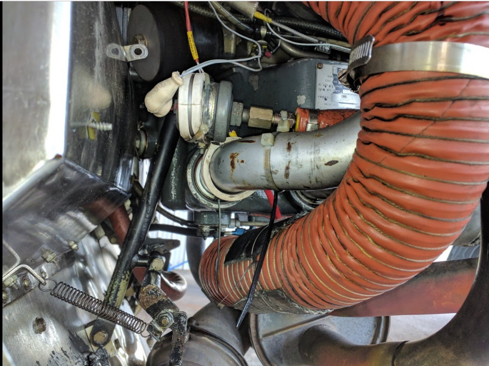
If I didn't know that the NPT fittings are anodized blue, I'd be up all night worrying that they had turned the color from all the leaks...but there really also isn't much on the interior of the fire sleeve (thank goodness). I don't have much faith in this particular sensor and I'm not going to change the fittings on it now. I'll secure it well away from the exhaust riser with Adel clamps tomorrow morning and then see how far off the K factor appears to be. When this was operating last year, it read ~1.7x what was actually consumed. That is, per my notes for a 1.2 hour flight with 2 approaches and a hold (much LOP), the Shadin indicated 16.5 gallons consumed but it took only 9.6 to top it back off to where it was before the flight. Not sure how to adjust the K factor to compensate for this but before I get into that, I'll want to see what the new ratio is now that it's cleaned and operating again. Cliff
-
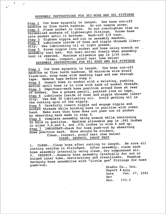
It may not be clear form the picture of the transducer, but the blue inflow NPT fitting is itself a 45 degree elbow. This installation may have been misguided in more ways than one.
-
Good point. Well, this thing has been in this configuration, wires bent, inches away from this exhaust riser for at least 20 years and perhaps 1500 hours of flight...so this is one more bit of luck.
-
You have all that correct. This is a nutty bad location for the fuel line to run and probably even worse to have a bunch of fittings and a mechanical sensor. I have no clue what motivated the original installer. (Incidentally, the reason I created this thread was because I couldn't find the FF transducer...and I was not looking for such a device right next to an exhaust riser.) I noticed that there was just a tiny bit of blue dye on the inner fire sleeve material when I took it off but nothing to indicate a real leak. More like stuff from installation time. That said, the fitting on the outflow was barely finger tight. Yes, I could have loosened it by hand. So the lack of a leak was just good timing in a game of Russian Roulette. I will see about getting my A&P to relocate this thing entirely but in the mean time, I will clean all this up and use Adel clamps to get it down and away from the exhaust riser. There's a good chance that this sensor has been abused beyond salvage...I'll find that out once I fly a bit. All I know at this point is that the setup doesn't leak and that the Shadin computer now reads fuel flow. Cliff
-
Mine is horizontal...per the spec sheet, the wires need to come out of the top of it for venting purposes but they don't call for absolute level or anything. I now have a lot of adel clamps so I'll get it away from the riser. It always looked suspicious to me. In the pics from a month ago, you can see that it didn't really have any clearance before I touched it. So many things about this engine setup are sketchy...sigh.
-
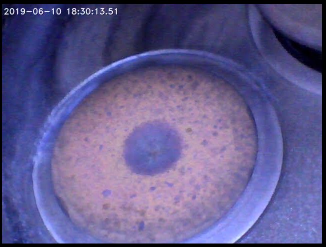
I finally got to take a look at the transducer. It's a Floscan Model 201. It has been sprayed with carb cleaner, soaked in Hoppes #9, and re-installed. It seems to work well now. My only question left is: is it a problem if the fire sleeve bundle actually touches the exhaust riser for C4? It was previously clearing the surface of the riser by perhaps 1 mm (so probably was touching a lot due to vibration) with no damage - just soot. But after re-assembly, it has less clearance and lightly touches the riser. I should mention that there are 2 layers of fire sleeve here, adding at least 1/2" of barrier around the transducer.

-
I really love the comments. Large and medium Adel clamps and bolts and nuts and everything in the parts catalog to deal with securing SCAT ducts has now been ordered. Also, smaller Adel clamps to get the JPI wires away from the magneto wires. Going to need to do something with the Tanis wires, too. The A&P who installed it didn't follow the manual's instructions about *not* bunching up excess wiring, so I think I'll need to get it trimmed to size and get the crimpers from Tanis and all that.
-
Thanks, Skip - I've read about soaking in Hoppes in other threads (e.g., "Hoppes comes in a plastic bottle...so no worries about your plastic impeller"), but I'm not sure which Hoppes product to get at this point. Cliff
-
Thanks, Andy...I'm only a little self-conscious about the setup under the cowl...I know it needs some attention and I'm more interested in getting advice than I am worried about looking like I don't know what I'm doing (because that part is true). I found the part #'s in the M20J parts catalog just now...looks like a couple of MS21919DG26 and -34. I'll get a few smaller ones for the JPI wires. I'll slowly get this mess sorted out. Cliff
-
Where can I find some large Adel clamps to get the scat ducts secured properly? I'm going to obsess about this now... Cliff
-
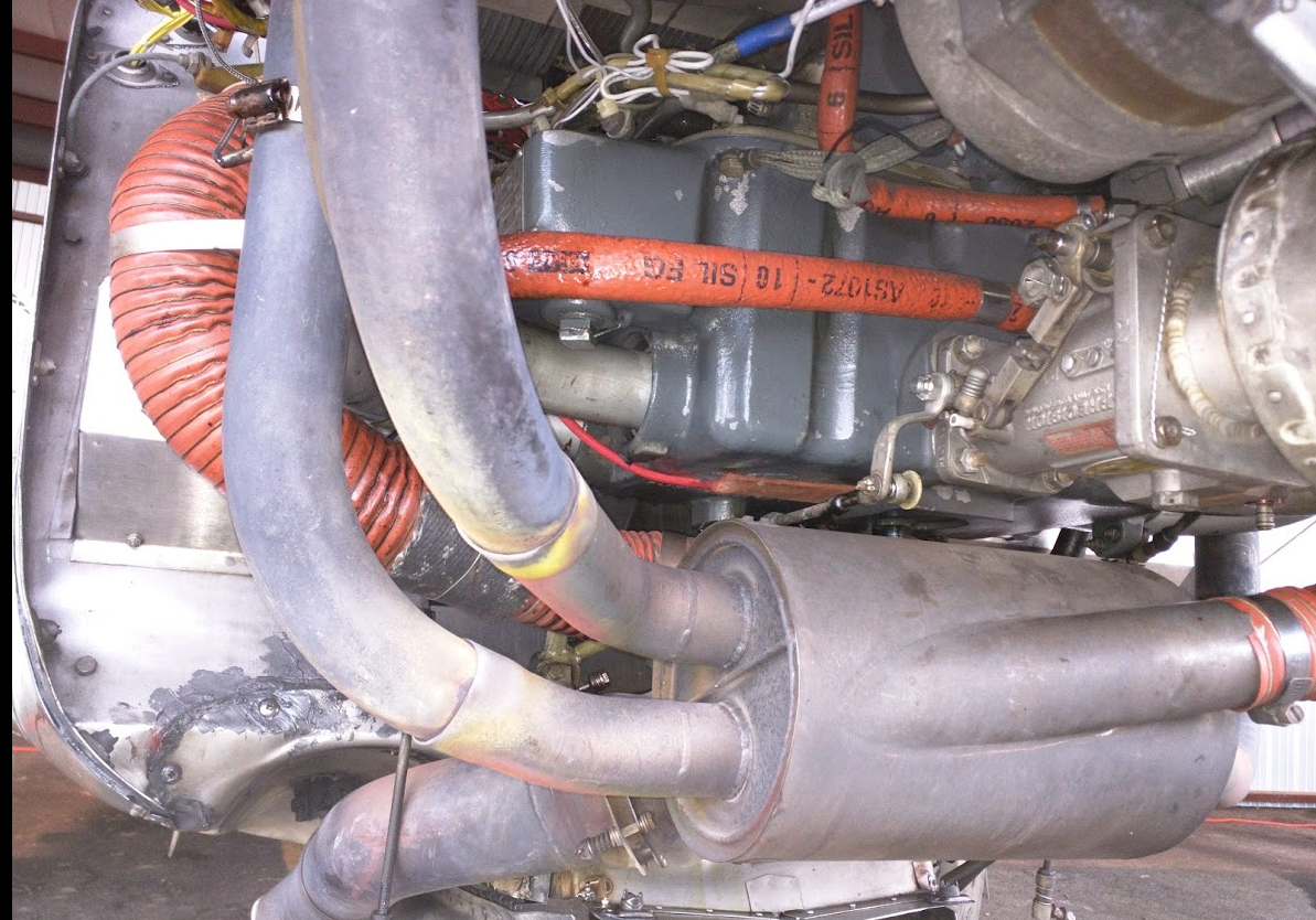
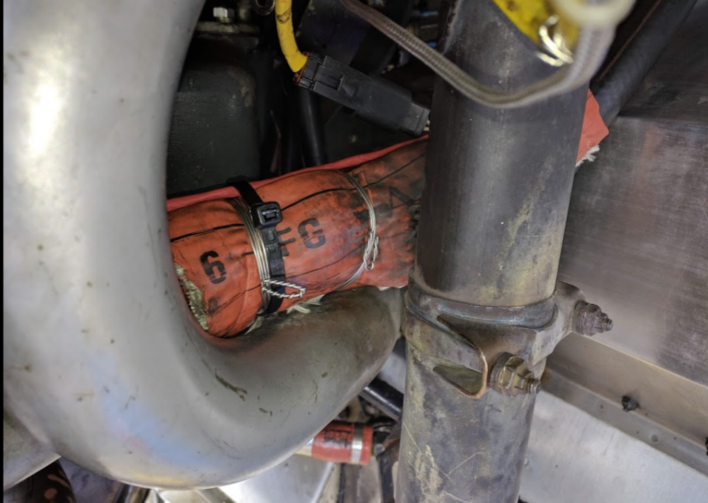
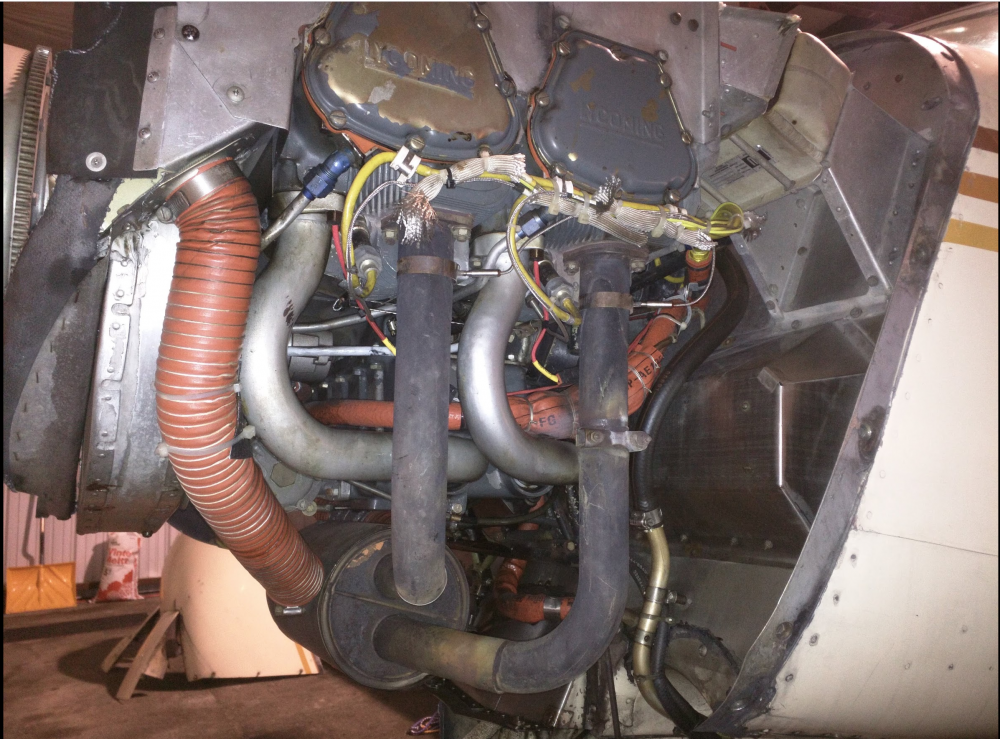
Here's a better view of the heater scat tube. Please keep in mind that the plane came from the previous owner in this configuration and these pictures were from last year, when I'd had the plane in my possession for about 4 months and hadn't done much work or cleaning. I think this might have been from the first oil change I did myself. Historically, the plane was leaking a fair amount of oil from the old rocker cover gaskets, so this was just after I'd had them replaced with silicone ones and some of the old leaking oil is still everywhere. Cliff
-
Fantastic advice, thanks as always! I often wonder if the way this engine was maintained by the previous owner's A&P was quite correct. I've found a number of oddities...some more serious than others.
-
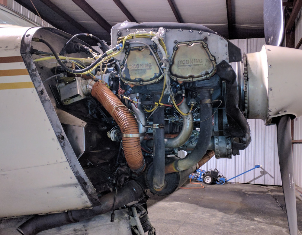
Wow, thanks for all the help! My A&P stood the lower cowl up like that one time and I just decided to copy how he did it. I can see in the picture that it is forcing the cowl hinges to bear a lot of the weight, so I will not do that again. I also see what you mean about the JPI CHT and EGT probe wires being zip-tied to the ignition wiring. Chance of inductive coupling is probably high. I'll correct that. Is there a standard kind of "stand off" that would go into a bundle like that or should I just find a way not to zip-tie the JPI wires to the magneto wires? Cliff
-
It's cleaner now, Tom! This is all from last year when I was looking under the cowl for the first time. But yeah, this plane needs paint in more than one place.
-
Thanks, Steve! I guess it must be in this fat bundle of orange firesleeve under C4 running right next to the exhaust riser.
-
Thanks, Clarence! So, I've been thinking about this backwards...this signal goes to the FP gauge in the cluster set at eye level...and the FF transducer that I'm looking for has yet to be found...by me. I'll look through more of my past pictures. I have a habit of taking lots of pictures from many angles almost every time I have the cowling off. Turns out to be helpful in times like this to go back and browse through them. Cliff
-
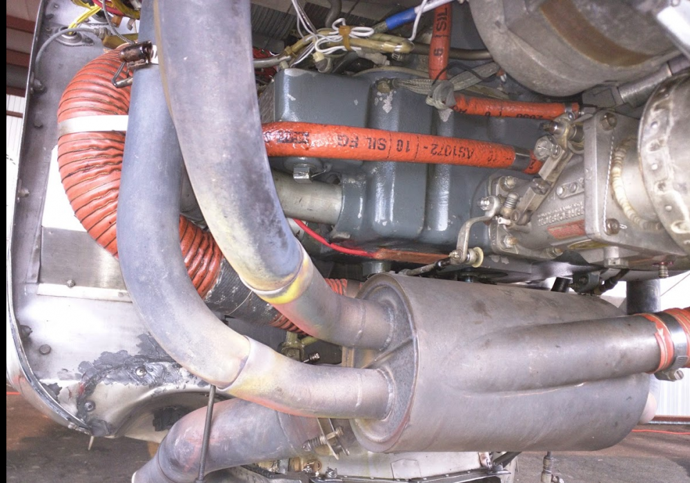
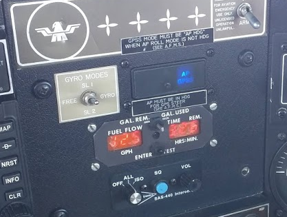
My Shadin (I believe it is a Shadin, pic below) has been flaking out for months, usually reading close to 0 GPH. I've searched for this and found a few threads on here but everyone seems to have an actual fuel flow transducer in a loop fed from the port on the side of the fuel distribution unit. Mine would seem to be a pressure transducer on a dead-end line from the servo. Can anyone tell me more about this sensor? (These are pictures from last year - there's a new muffler and a lot of cleanup since then!) The supply goes back around to the servo here: Here's the FF computer in the panel.
-
Update. I went in again (carefully) with the bore scope and the scratches are gone! The cylinder has had 8.75 hours since the last time I scoped it, when I scratched the deposits with the brass end of the bore scope. Total time on this cylinder is now about 18 hours.

-
Do you carry a personal transport device in your Mooney?
FlyBoyM20J replied to 231LV's topic in Modern Mooney Discussion
I just use a couple of contractor bags from Lowes (ya know, the ones that come in a 50-pack for like $25). They're 3 mil thick and easily hold a 700 cm road bike wheel. I'm also not very tall so I can put my whole road bike frame in another one if I like. Only downside is they smell like someone's idea of how a clean garbage bag should smell. -
That's good to know. I've heard only great things about working with GAMI and I look forward to this process. I should mention that my brief excursions into 65% LOP cruise in the last couple of post break-in flights have shown greater stability farther from peak than I could run prior to GAMIs or the C2 overhaul. I believe I now run 50F to 80F LOP stably at 2400 RPM at 6-7k MSL. That could be GAMIs or could be that C2 no longer has a sticking EV. Or both.
-
Yes, I didn't research my need for GAMIs well enough. I thought that I had a healthy engine that wouldn't run stably past 30F LOP and was sure that installing GAMIs would give me better balance. Sequence was like this: 1) Bought plane April 2018 2) Worked out how to do LOP flying September 2018 3) Determined that engine ran well (without doing inflight LOP mag test, since I didn't know about it at the time), but that LOP was stable usually to 20F and never past 30F LOP. 4) Decided GAMIs were the answer. Put them on the list for stuff to buy soon. 5) C2 EV stuck hard 29 APR 2019, bent push rod, C2 sent to Jewell for overhaul 6) Ordered GAMIs since engine was taken apart and this looked like the time to install 7) Re-installed C2, did break-in for 10 hours 8) Installed GAMIs at 10-hour oil change. Once I installed the GAMIs, I saw very similar ROP behavior to what I saw with stock injectors for ROP, even with the recently overhauled C2. Visually, the graphs on the EDM-700 look more uniform with GAMIs than with stock injectors, but the downloaded data looks about the same for ROP. I never ran LOP for the initial 10 hours of break-in. So, I have lots of JPI data for stock injectors ROP and LOP, but only 3 break-in flights of data for stock injectors and the overhauled C2 prior to installing GAMIs, and all of those break-in hours were ROP. The annotated JPI graph is from post-GAMI flights in which I started to go LOP and do the LOP mag test. I suppose the good news about GAMIs, though, is that I can work with GAMI to get a good balance with the new C2.