

FlyBoyM20J
-
Posts
184 -
Joined
-
Last visited
Content Type
Profiles
Forums
Blogs
Gallery
Downloads
Events
Store
Everything posted by FlyBoyM20J
-
Help identifying air duct for 1982 M20J
FlyBoyM20J replied to FlyBoyM20J's topic in Modern Mooney Discussion
Thanks Clarence! -
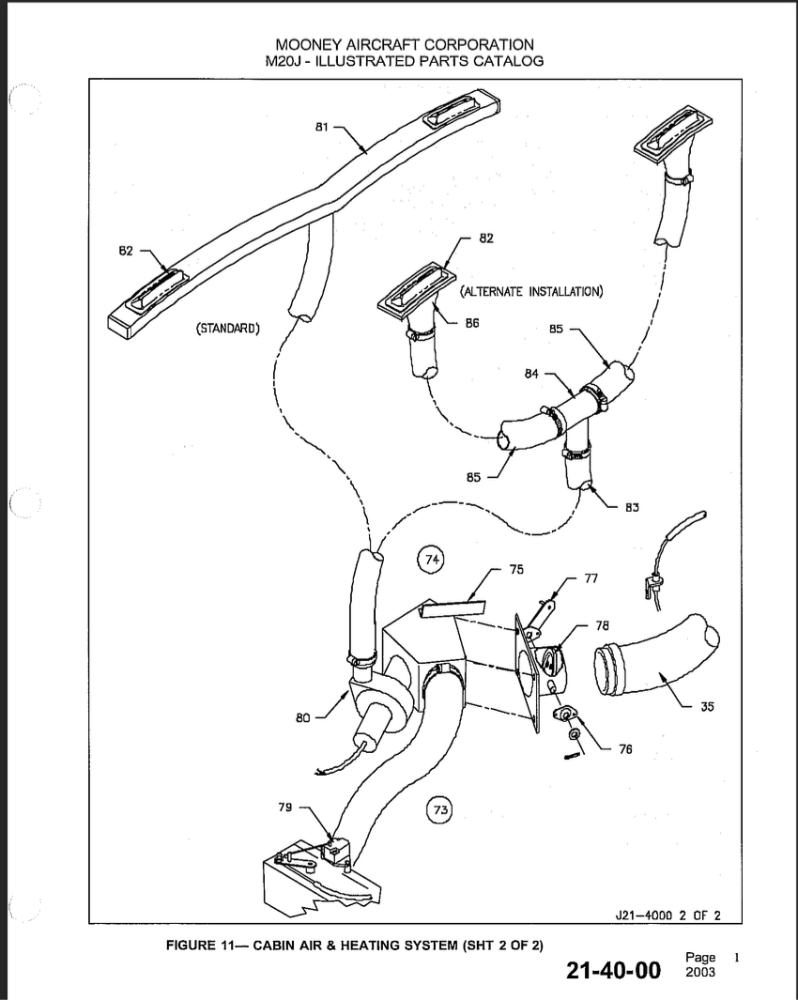
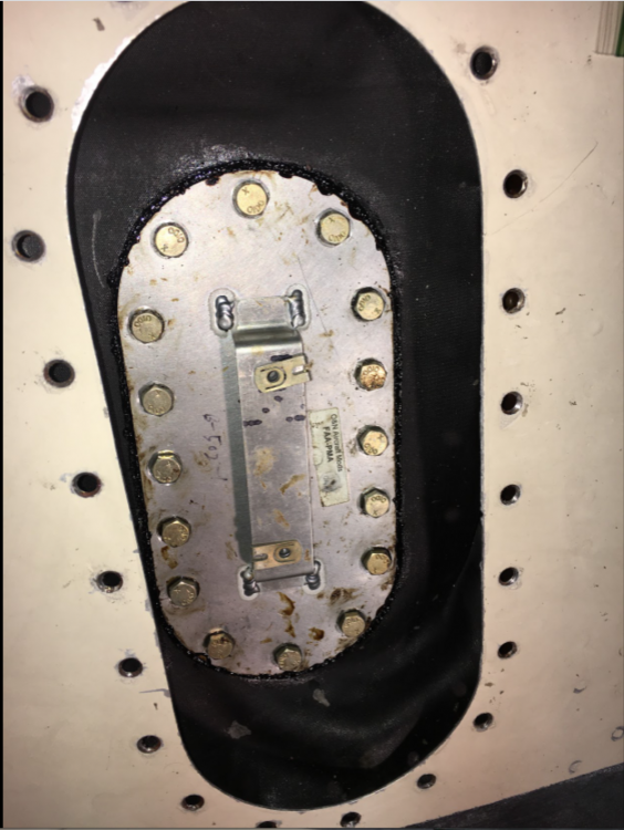
This duct is disintegrating so I didn't want to take it off to see if it has a more complete PN on it. This is co-pilot side, and the plane's SN is 24-1298. I'm not 100% sure which duct it is in the IPC diagrams (attached)...I think it must be item 35, PN 912007-503 but I'm not finding that part online easily. Has anyone had any luck replacing or repairing this duct? Thanks again, Cliff


-
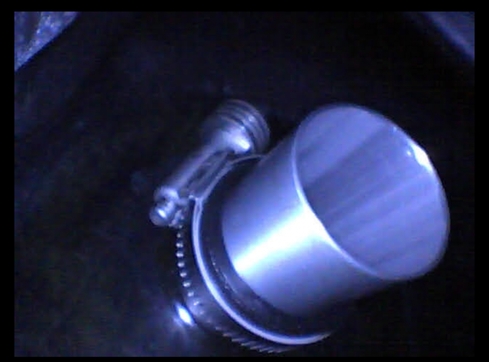
All, my apologies, I got sidetracked since I was able to fly that same day once the problem was solved. It was a bad GND connector on the back of the alternator. I am reviewing everything now because this alternator needs replacing soon if not sooner. Here's the connector...doesn't look too bad, but it also looked uniformly "dusty" as if it hadn't been touched in some time. When we loosened the bolt, lots of mineralized dust fell down from between the washers, the lug, etc. We cleaned it and the other end, and that was that. Perfect charging for 2 startups on the ground and then I took off on a longer XC flight (some 6 hours in 2 legs, no issues at all). Cliff

-
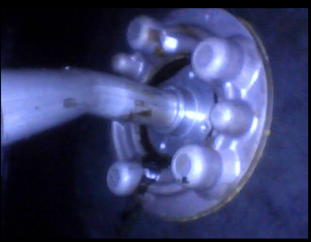
1982 M20J, SN 24-1298 My alternator seems to have kicked the bucket. Intermittent lack of charging last couple of flights that corrected itself once, so I was looking for a bad FIELD connection; cleaned that and tightened it; no luck at run-up this morning. Also, should mention: the belt is in great shape. My A&P and I replaced the belt shortly after I bought this plane about 4 years ago. With engine running on ramp: HIGH/LO VOLTS annunciator is flashing, so per the POH, this is a low-voltage situation. Ammeter is discharging and JPI reports 12.5V. Toggling ALT FLD and ALT breakers and MASTER has no effect on the situation. Back in hangar, FIELD wire looks good, VR looks new (is in excellent position above copilot's left knee). I realize I need to measure the FIELD current to be sure, or at least ring out the wire, but based on the findings above, it seems like time for an alternator and I can ring out the FIELD wire when I replace that. I realize this does not rule out the VR but the visual inspection suggests all is well with VR, wires and FIELD all the way to the stud on the back of the alternator. Also, I'm not sure how a failing VR internal circuit would self-correct like a mechanical system would, or like a bad connection would. But I'm not well versed in these systems. Looking at the logbooks, this alternator (and the VR) seem to be original equipment. No mention of them in the logs. Here's the information plate: The Lycoming IPC has PN LW-14333 for alternator ALY-6420LS for IO-360-A3B6D, and Spruce lists the ALY-6520R as the correct replacement for the LW-14333. But there's also an ALY-6520RLS, below that one, at this location: https://www.aircraftspruce.com/catalog/elpages/electrosysalt1.php?clickkey=504227 Does anyone know whether I should get the ALY-6520RLS version or is the information in Spruce correct, and I should order the ALY-6520R? Thanks again, Cliff

-
Update, 3 weeks later, it is fixed! Thanks a million to Dave & Lisa at Air-Mods in NJ! Perfect fit! Flew home after the install and, if anything, there is less vibration now than at any time in the last couple of years. That said, I will have it balanced ASAP. Thanks, also, to Clarence @M20Doc, who has a part and was going out of his way to help me on his vacation a couple of weeks ago. The local mechanic where I got the plane stuck *thought* he had found a part right away so Clarence said go with my mechanic's find, but that turned out to be the wrong part. Meanwhile, Dave from AIr-Mods had had a chance to visit his Georgia location and brought this one back with him. Thanks, not least, go to the local mechanic but I'm not sure he wants to be on the internet so I'm leaving his name and the field location out of this post. He rocks, though. Cliff
-
We'll never know...this was (in fact) to be the last flight prior to going on jacks for annual. No evidence of cracks at the last oil change, either (30 hours ago), at least, nothing that caught my eye. Annual under an IA's watchful eye might have caught it...I'd like to think so.
-
Thanks, Clarence! I saw your DM and will email you...enjoy vacation! Cliff
-
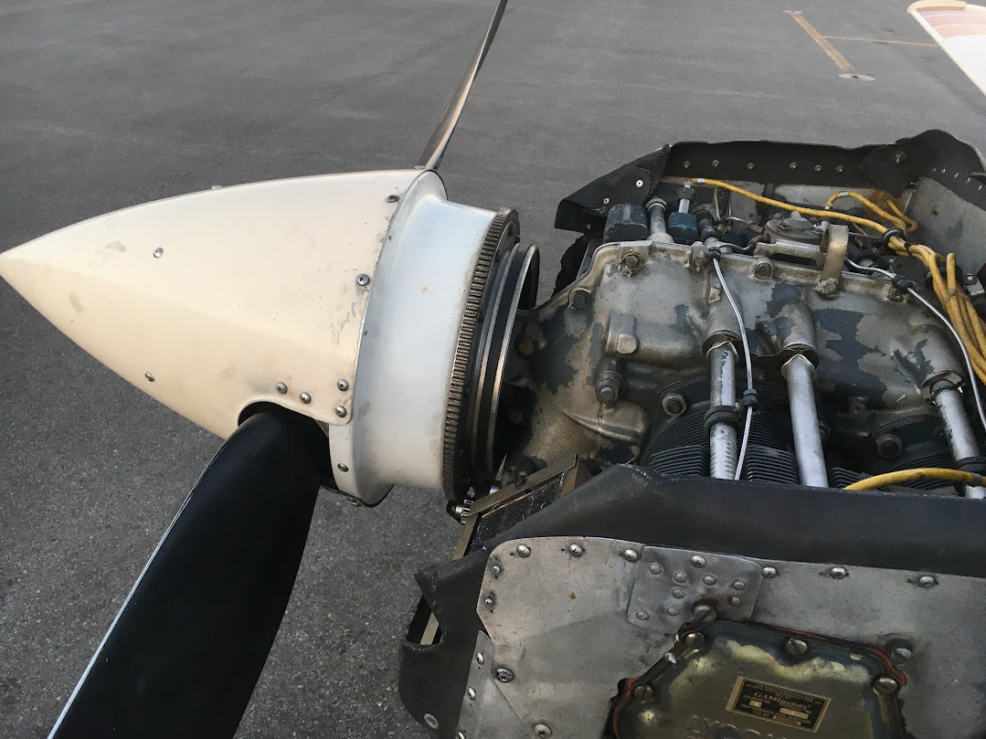
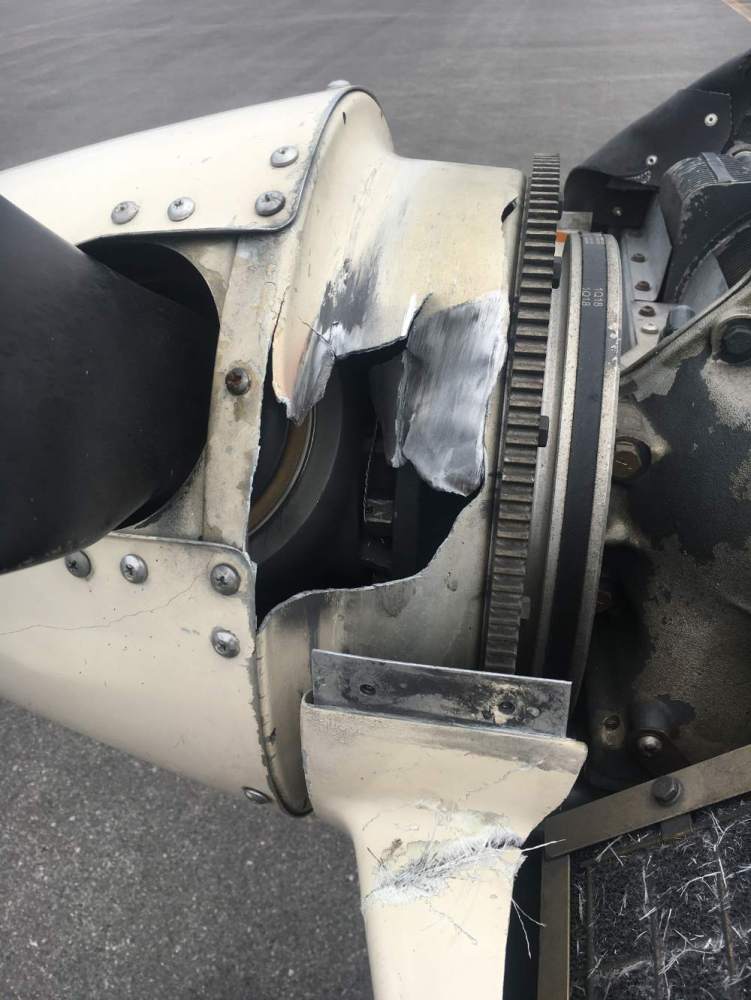
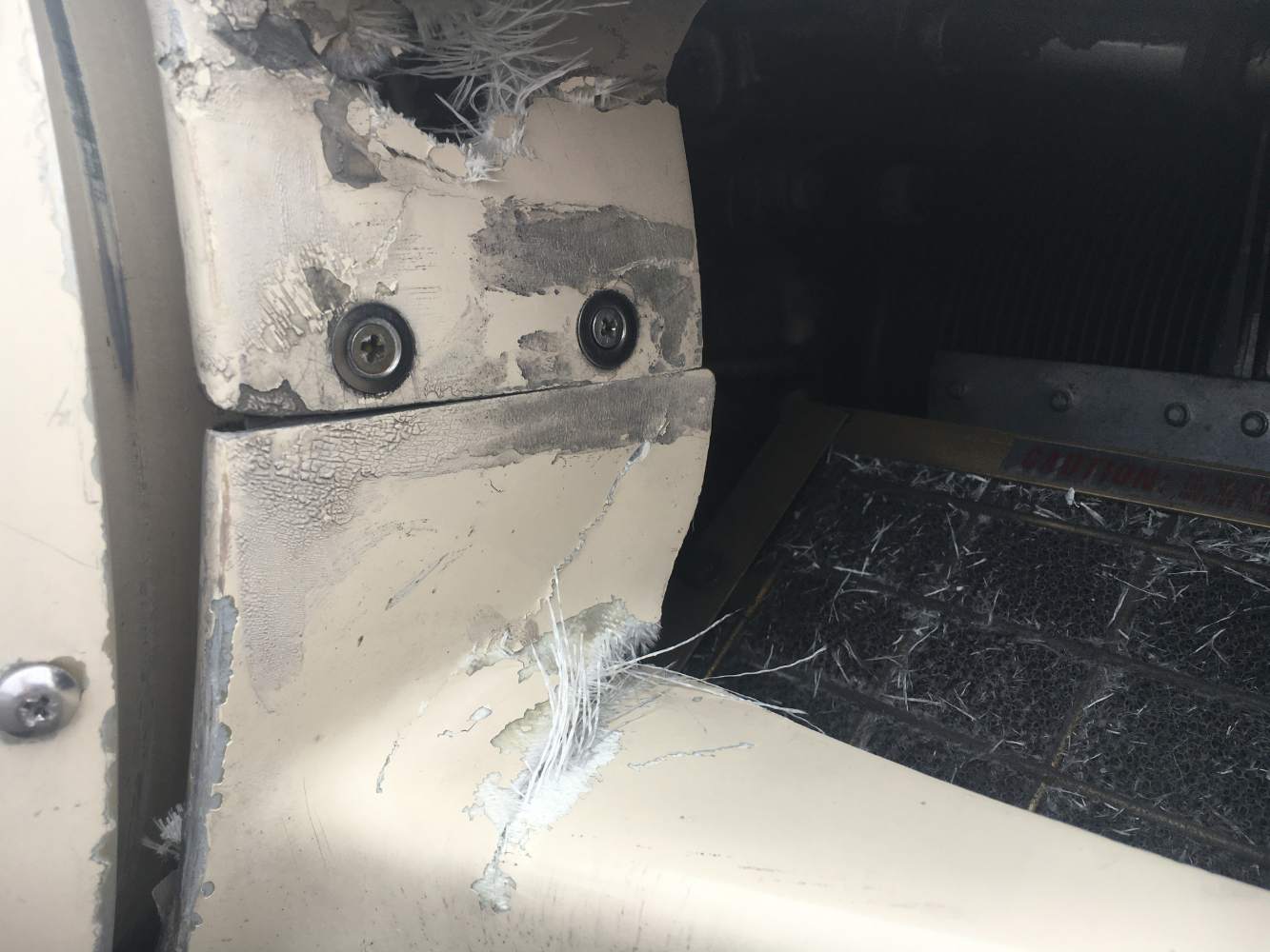
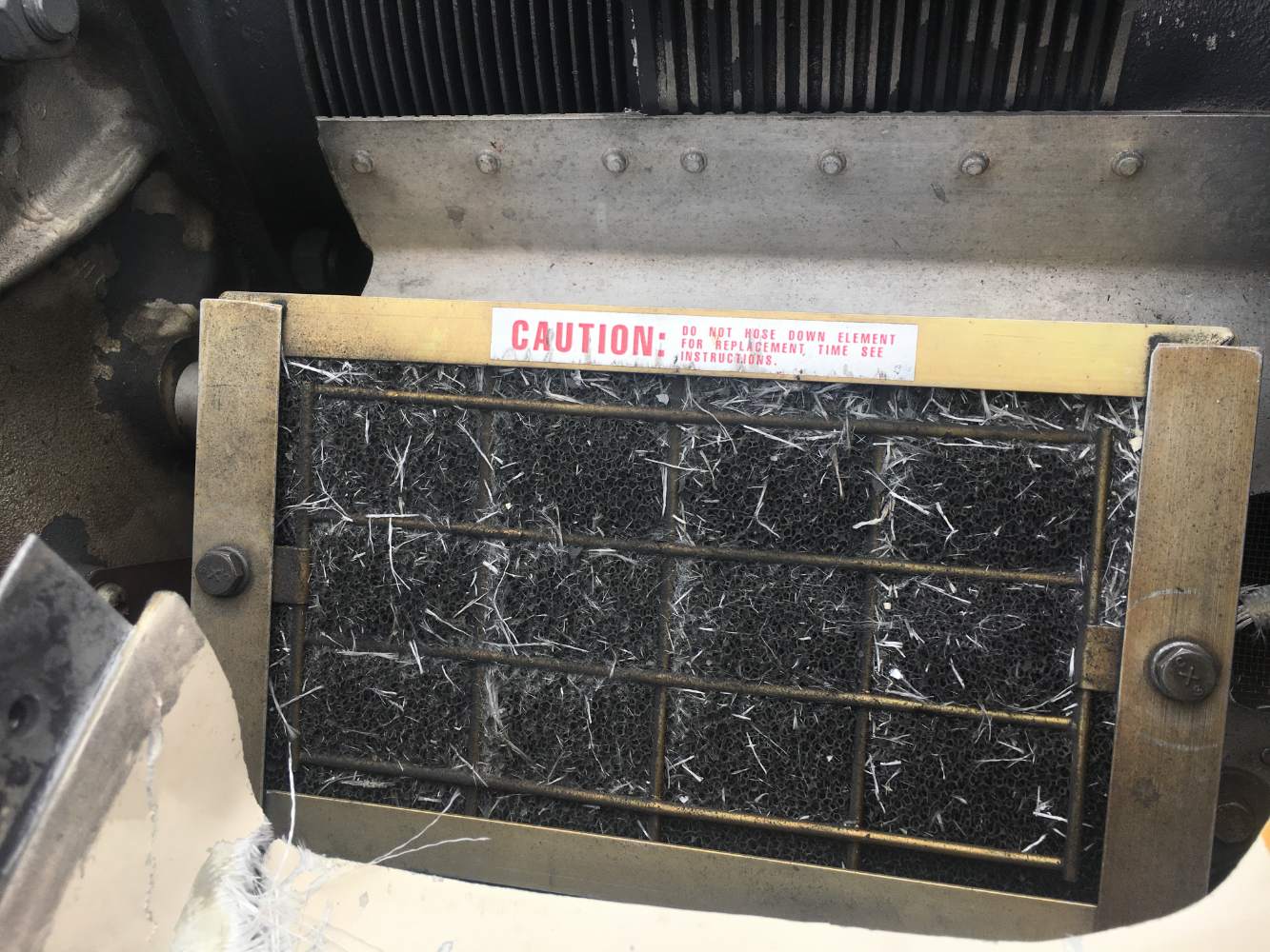
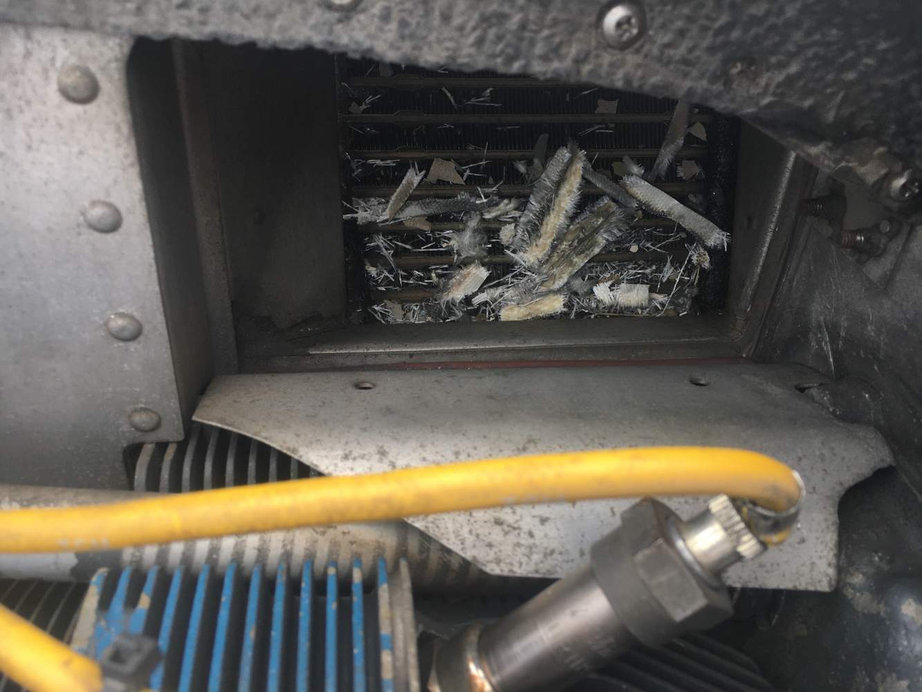
The plane is a 1982 M20J, SN 24-1298. I and a safety pilot were up for some approach work yesterday when we both heard a loud noise from the engine...no real vibrations (going along at ~25.5", 2550, 160 kts TAS, 4k MSL, VMC), but the noise got louder over perhaps 20 seconds such that I and my co-pilot agreed that it was real...and I was sure I had never heard it before. It sounded like a chainsaw engine revved up and getting closer (growing louder, but constant pitch). About that time, we could both smell a whiff of smoke. I removed the hood (yeah, this was fun to figure out with that thing on right at the beginning), and there appeared to be a tiny bit of smoke coming from behind the spinner, so I immediately pulled power back, checked pressures, temperatures, JPI graphs, all good, and the noise lessened with lower RPMs. I notified ATC and diverted to the field right below us, did uneventful landing in VFR conditions, and pulled the top cowl on the ramp for a closer look. This is what we found...no other issues anywhere on the plane, no more oil on the gear doors than I'd expect for an hour of flight, etc. And a fair bit of chewed up fiberglass stuff in the intake filter and at the oil cooler. JPI engine data from this flight looks like any other recent flight. Engine unaffected, at least, in the couple of minutes that it was running between pulling back power and shutting down on the ramp. So, looks like I need a new bulkhead. Given my SN, this would be PN 680031-017. Any leads? I have already talked to Dave @ AirMods and he thinks he has one in his GA "warehouse". But that's uncertain and he's not going there for a while. Looks like I am going to need some fiberglass work, too. The top cowl got a hole punched through it (see pic) and there's one on the opposite side but it is otherwise undamaged and assembles like it always did. Bottom cowl has some minor damage. Cheers, Cliff
-
Just saw this...I don't have any fluctuations as long as I've manipulated the spade connectors on the back of the master switch recently. Meaning, every 6 months or so, I start to see the ammeter needle move slightly and so I generally take the spade connectors off the back of the 4 spade lugs, inspect, and put back on...and problem solved until a few months later. I can only assume some oxide is building up but I can never see anything. Most recently, I didn't even remove the connectors. I simply touched them and the needle stopped moving. That was a couple of months ago, so I expect I'm about due. Cliff
-
Both wing strobes suddenly no longer work
FlyBoyM20J replied to FlyBoyM20J's topic in Modern Mooney Discussion
This sounds perfect...is the STC included? Cliff -
Both wing strobes suddenly no longer work
FlyBoyM20J replied to FlyBoyM20J's topic in Modern Mooney Discussion
Thank you! I am away from my plane for a few days...back at it next week, and if I decide to stay with Xenon tubes and Hoskins, I'd be grateful for a working Hoskins unit. I'll dm you my phone number at that point...don't want to make you dig through your parts unless I'm going that route. Cliff -
Both wing strobes suddenly no longer work
FlyBoyM20J replied to FlyBoyM20J's topic in Modern Mooney Discussion
This looks perfect! I have the same wing tip extensions/fairings...Will check website, but I'm assuming that the way to wire these LEDs would be to bypass the Hoskins units in the wings...would be nice to remove them but they don't seem to cause much of a problem. Cliff -
Both wing strobes suddenly no longer work
FlyBoyM20J replied to FlyBoyM20J's topic in Modern Mooney Discussion
I found this, so I guess I can fix the broken PS (thanks NicoN!), but I'm leaning toward LEDs at this point... Cliff -
Both wing strobes suddenly no longer work
FlyBoyM20J replied to FlyBoyM20J's topic in Modern Mooney Discussion
Has anybody done this with Lasar wing farings? I have those on this plane.... -
Both wing strobes suddenly no longer work
FlyBoyM20J replied to FlyBoyM20J's topic in Modern Mooney Discussion
This is what is in the maintenance manual...so...likely a bad Hoskins PS that can be isolated by disconnecting SYNC as N201MKTurbo suggests?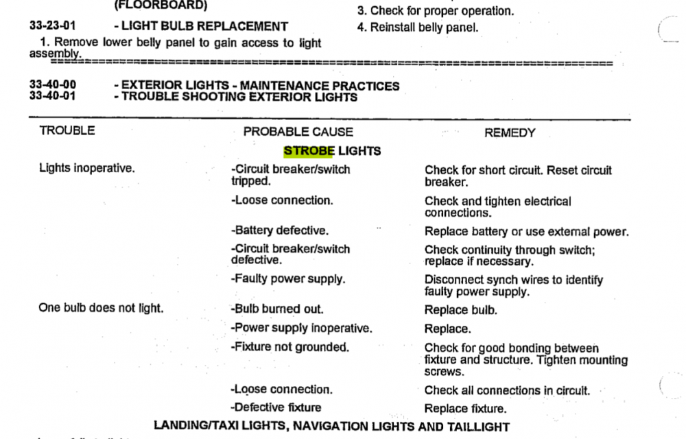
-
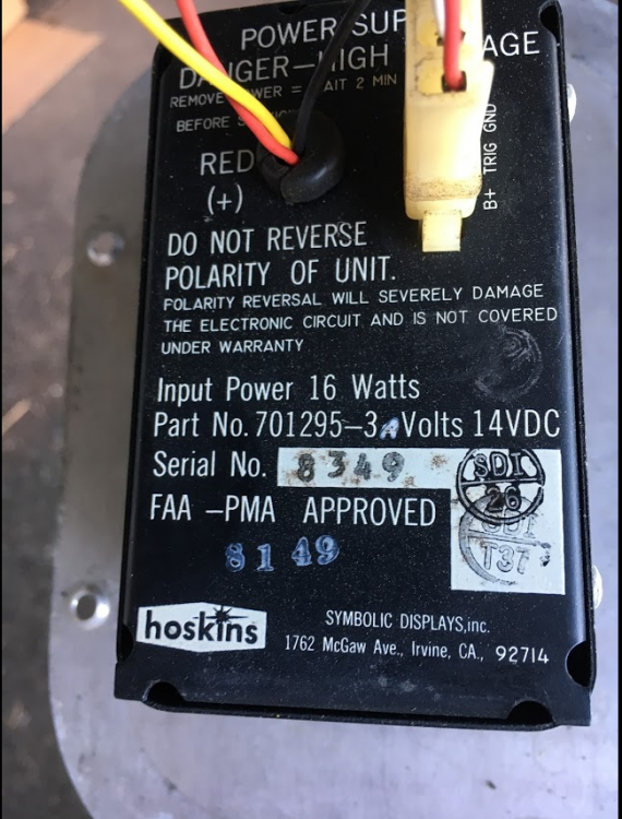
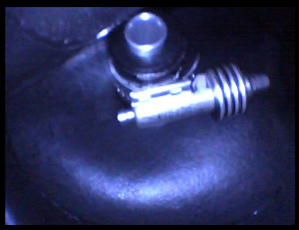
I always check the lights during preflight and one day last week, no strobes. The day before, they were fine. I got a chance to look at this today and the voltage coming out of the Klixon breaker is > 12V, and the power reaching each of the Hoskins strobe PSs in the wings is > 12V. The B+ wire for the right-hand strobe measures around +500V DC and the B+ wire for the left-hand strobe is about +470V DC. Nothing on the Trig lines going to either strobe tube, and nothing on the SYNC line coming into either PS. GND is good at PS inputs and at strobe molexes. No tail strobe light on this plane, but the strobe PS is in the tail cone. Didn't measure anything at it but nothing looks amiss looking from the vicinity of the battery. Is it possible that *both* of my strobe tubes died at the same time? Or does one dead tube inhibit the other PS via the SYNC line? Cliff Pic of a PS in the wing (both are same):
-
Leaky fuel bladders in 1982 M20J
FlyBoyM20J replied to FlyBoyM20J's topic in Modern Mooney Discussion
An update for anyone who was wondering: it was indeed the CT clamp on the 1.5" interconnect between B and A cells in the picture above. Before I corrected this, I talked with Nate at Griggs and he said that clamps on this interconnect in particular are known to come loose over time and that 90% of the time, the only thing they do when faced with a leak in their shop is open up the cells and tighten all the clamps. They do not try to locate the source of the leak most of the time, as that is not easy and can take a lot of time. It now looks like this: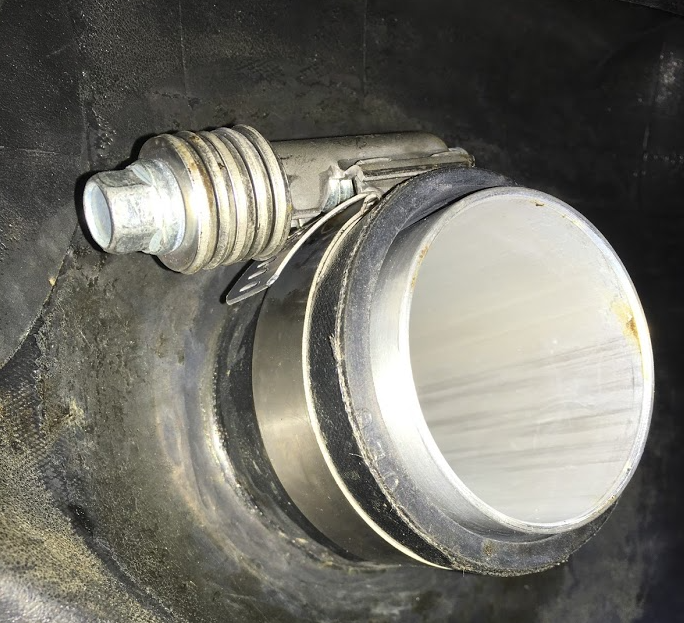
-
Leaky fuel bladders in 1982 M20J
FlyBoyM20J replied to FlyBoyM20J's topic in Modern Mooney Discussion
And...the bladder access panels are open! The Permatex was not as pervasive as I feared and it was possible to use a plastic putty knife between the gasket and the fuel bladder...no real pressure required and slowly things came apart. Inner cell: Middle cell: Most of the clamps appeared correctly installed except for this one which is on the 1" mid-height pipe between the middle and inner bladders, as seen from inside the middle bladder looking toward the inner (cabin side). My mechanic will inspect before I move forward. Cliff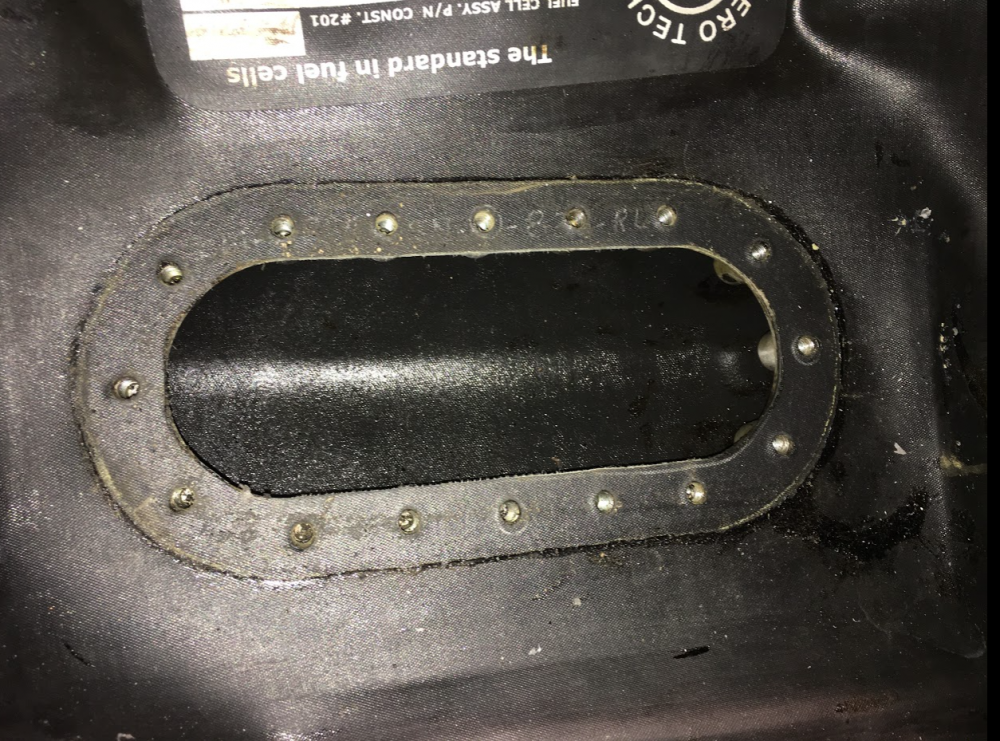
-
Leaky fuel bladders in 1982 M20J
FlyBoyM20J replied to FlyBoyM20J's topic in Modern Mooney Discussion
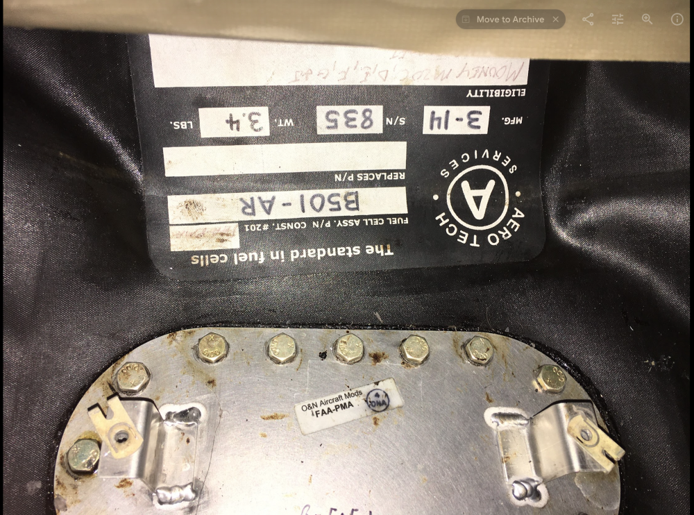
There's a bag on eBay right now that was refurbished by O&N, and the pictured receipt shows about 40% of an AMU. From perhaps 5 years ago. I'll get mine repaired if necessary but at the moment, I am willing to believe that a single interconnect clamp requires torqueing. The trick is to access the clamp without damaging the bladder. I believe I can remove the Permatex-infused cork and with some very careful clean-up, keep things in good shape. I just talked to Griggs to order some more gaskets at $20 each. Arriving in a day or 2. -
Leaky fuel bladders in 1982 M20J
FlyBoyM20J replied to FlyBoyM20J's topic in Modern Mooney Discussion
Thanks! I've been to Griggs a couple of times. Those are some great and talented people. I'm pretty sure I'm looking at a good quantity of Permatex No. 3 here. These bladders were installed by the mechanic used most often by the previous owner...and that mechanic is fond of Permatex No. 3. You can see the stuff ran down the inside of the fuel sender in the borescope picture, as well. I would bet that if that particular mechanic installed anything that had a cork gasket, he'd Permatex it up for good measure. Wonderful guy, though. The next step is to open the access panels to allow inspection and torqueing of interconnects. If I had to open only one bladder panel, it would be the inner (cabin side) since that's the chamber with the odor of fuel and barring a perforation at the bottom of the cell, odds are it's an interconnect clamp accessible from that cell. I'll call Griggs later this morning and ask if they'll sell me a set of cork gaskets. I already have a full set of CT clamps coming in case I open up a bladder and see something amiss. Cliff -
Leaky fuel bladders in 1982 M20J
FlyBoyM20J replied to FlyBoyM20J's topic in Modern Mooney Discussion
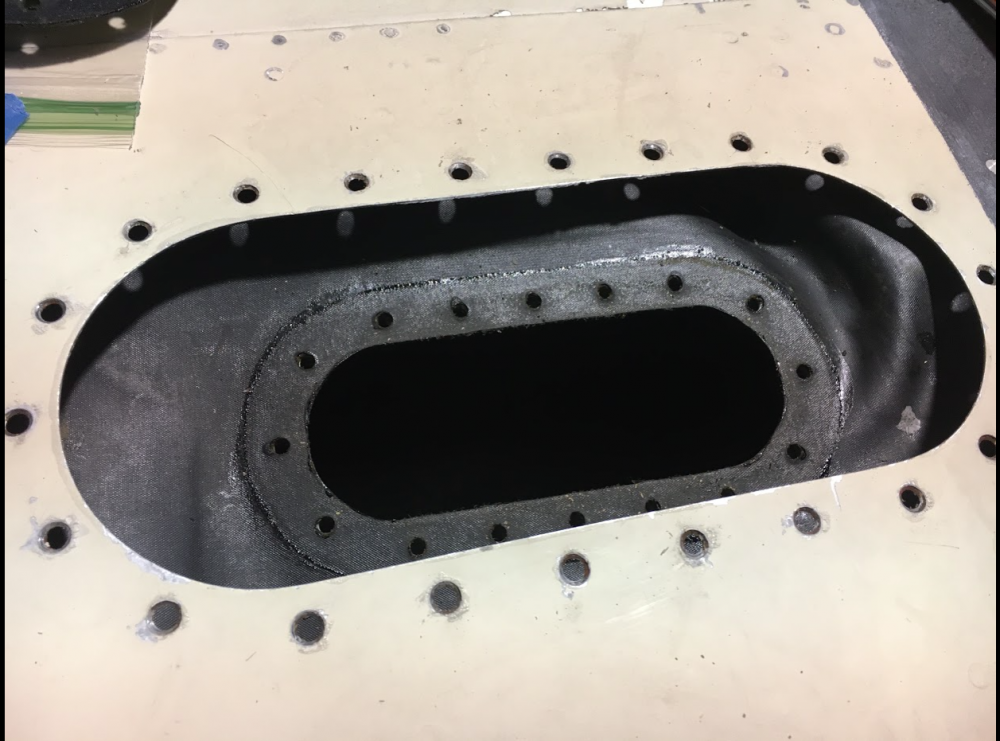
Panels opened today. Borsecoped outermost cell via fuel filler opening. Looks good so far but there's no indication that the problem is with the outer cell. Fuel smell inside innermost cabin-side cell chamber, which makes sense given the locations of the leaks on the bottom of the wing. No fuel cell access panels show signs of weeping, likely because the installer used Permatex on the cork gaskets. Suspect an interconnect clamp on upper or mid pipe between inner (cabin-side) and middle cells. But...so much Permatex on the cork. Did not attempt to defeat yet and it's clear I'm going to need replacement cork gaskets at a minimum. Going to talk to Griggs tomorrow about those.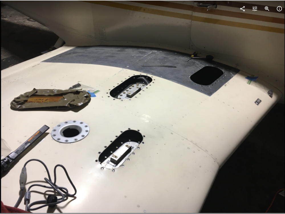
-
Leaky fuel bladders in 1982 M20J
FlyBoyM20J replied to FlyBoyM20J's topic in Modern Mooney Discussion
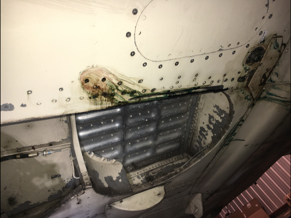
Yes, it does leak out at the sump drain but doesn't seem to be originating from there. The browner stain farther outboard is the first indication of fuel leaking along the wing - the lighting isn't good in this photo, but that is basically goo that flowed with leaking fuel. It seems to flow downhill from there inside the wing and drip out at the opening around the sump drain...and past that down to seams in belly panels. As it happens, the cover plate at the sump drain has a cutout that allows one to see the nipple and the hose clamp...and would allow any leaks to drip out immediate at the drain rather than build up. Also, any leaks that originate elsewhere are likely to make their way down to that point and drip. The drip isn't constant or even evident, though. I think that the leak stops after the fuel level drops by 3 or 4 gallons, so that would also rule out the sump connection itself. I do know the mechanic who installed it for the previous owner. I talked with the previous owner just yesterday and he recalled that there was some leaking just after the bladders were installed, and that the mechanic had to add some clamps to interconnects. Unknown which side or which cells. So there's that anecdote. I also have met the gents at Griggs (current STC holders) and 76N is not far from my usual routes. But they are very busy and my local mechanic thought it would be good experience for me to work on this one and report back to him. Now that I have emptied the cells, I will pull access panels and check for any evidence of exterior seeping. I hope to see something but failing that, will just retorque interconnect clamps and clean everything prior to refilling to check for leaks. Cliff -
Leaky fuel bladders in 1982 M20J
FlyBoyM20J replied to FlyBoyM20J's topic in Modern Mooney Discussion
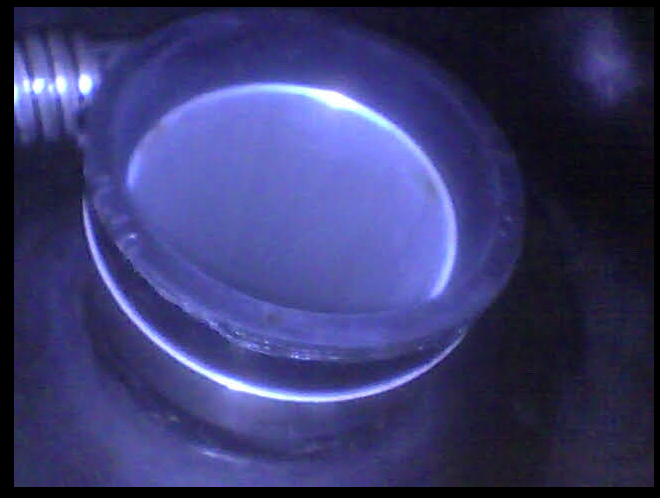
I had a look at this today but needed to get the fuel out of the bladders, so didn't get the access panels open (other than the outermost one next to filler cap). There was no evidence of seeping at that access port. Also, after sitting for almost 2 weeks in the hangar after being filled to the top, this wing ended up still having approx. 23 gallons. It would seem the leak is near the top of a cell, since the apparent low level is reached soon after filling and the leak seems to stop or slow after that. I have some exterior photos below. I'll get borescope pics and open access panels tomorrow. I can also say that the problem is a bit unlikely to be the fuel sender since it is affixed to the outermost (and highest) side of the outermost cell. But I'll open that panel tomorrow, too, so as to view the other side. Here's the view from the top: And the view of the leaks from bottom. The outermost leak appears along the line between the middle and innermost cells, roughly along the outer line of the tread paint.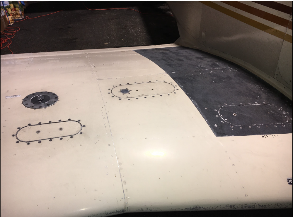
-
Leaky fuel bladders in 1982 M20J
FlyBoyM20J replied to FlyBoyM20J's topic in Modern Mooney Discussion
No fuel dye is evident on top of wing and the access panels installed in 2104 on top and bottom appear sound and sealed still. The telltale blue dye is around seams near the flap juncture at the back of the wing about 12" out from the sump...and of course, continues down to the sump (where it drips slightly) and on down to the nearby belly panels. As I mention above in response to @INA201, I think that this may be a case of a fuel sender gasket since the leak seems to happen most when the tank is full and I find the level of fuel has decreased only a few inches until the float arm is about level after a few days of sitting. But it doesn't seem to leak quickly past that point. Cliff -
Leaky fuel bladders in 1982 M20J
FlyBoyM20J replied to FlyBoyM20J's topic in Modern Mooney Discussion
This is a strong possibility...the leak seems to happen only when the right tank is full and I always find the fuel level is down a few inches from the filler cap with the float arm roughly level a few days later. The leak then seems to slow or cease at that level. Cliff


