

rotheroe
-
Posts
6 -
Joined
-
Last visited
Content Type
Profiles
Forums
Blogs
Gallery
Downloads
Events
Store
Everything posted by rotheroe
-
Repairing a Hoskin Strobe power supply (P/N 701295 3A14VDC)
rotheroe replied to NicoN's topic in General Mooney Talk
Thanks, btw I forgot to include the Littelfuse CG230 gas discharge tube that goes from the 0.22uF capacitor ("sync" input) to ground. This device will trigger (short to ground) once the lower 200uF capacitor has reached 230VDC and dump the charge from the 0.22uF capacitor into the step-up transformer (located in the strobe light assembly) to trigger a flash. The yellow sync leads from all three power supplies (wingtips and tail) are connected together so that whichever supply's CG230 first reaches 230VDC will trigger a flash on all three synchronously. If the yellow sync lead is simply left open (e.g. power supply bench test), this small gas discharge tube is what will trigger a flash. -
Repairing a Hoskin Strobe power supply (P/N 701295 3A14VDC)
rotheroe replied to NicoN's topic in General Mooney Talk
Here's a hand sketched reverse engineered schematic in case of use to anyone else repairing these themselves. I've had to replace the two big capacitors twice on one unit, since I neglected to reform the identical (Sprague 39D series) "new old stock" replacement units I bought from Mouser. The first (not reformed) set shorted out after a few months in service. The second set I reformed overnight on a high voltage power supply before installing them, so hopefully they'll last longer. The original soldered leaded small glass fuses are Bussmann GFA-4 and quite expensive.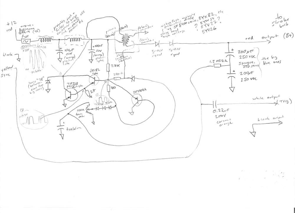
-
The top tip is a smaller diameter black plastic piece that needs its smaller diameter to slide into the narrow black plastic insert at the very top of the indicator panel slot. Unfortunately that means not just painting the tip of the rod black. The main rod measures less than 3/16" diameter, but more than 1/8". There is a small spot on the side that suggests injection molding instead of just standard size rod, which would be strange considering the low volumes involved. At any rate the rod is the maximum diameter that will slide into the indicator panel slot, so I'd have to go with 1/8" if fabricating the part. An original is about $70 (!) from Mooney, but there is no stock availability.
-
Thanks for sharing. Here's what it looks like in a 1980's M20J (SN 24-1169 to 24-3410). The first picture is from the rear, showing the trim and flap indicator screwed onto the backside of the plastic center console cover, with the illumination light socket on top. The indicator rods are round plastic on these years, with a small black plastic tip glued onto the top. On my M20J the flap indicator plastic rod snapped off at the base where it joins onto the wire (at the top of the red heat shrink in the photos). I glued it with epoxy as a temporary fix and am now looking for a new indicator rod. There is some tension on the wire cables (pushing towards the cockpit along the pitch axis) which is probably what eventually led to the plastic rod cracking and breaking off. -Pete


-
Larryb, it seems his was sold. He listed both this -511 as well as a -503 in a different posting last year and both are sold. My 1983 M20J uses the -511. Were all gauges on yours working when removed, especially the CHT gauge (my immediate need)? Is yours also complete with cable harness and connector? Would you send me a picture(s) rotheroe3-at-aol.com? -Pete
-
Hello, is your M20J gauge cluster still available? Pete Rotheroe rotheroe3 at aol.com


