Search the Community
Showing results for tags 'dome light'.
-
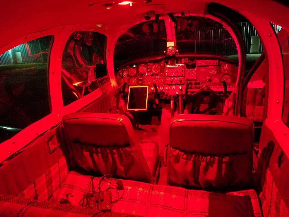
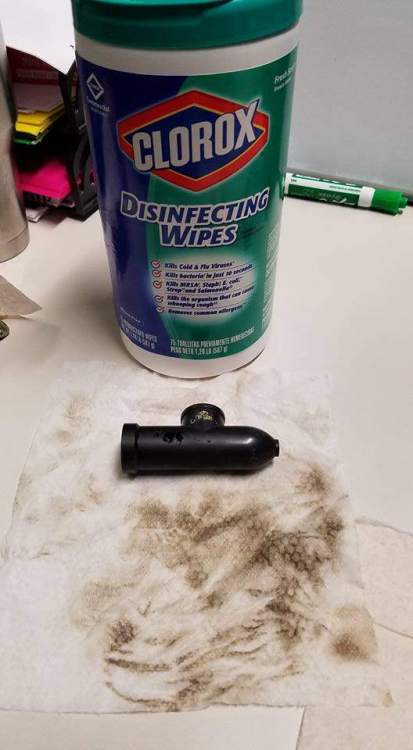
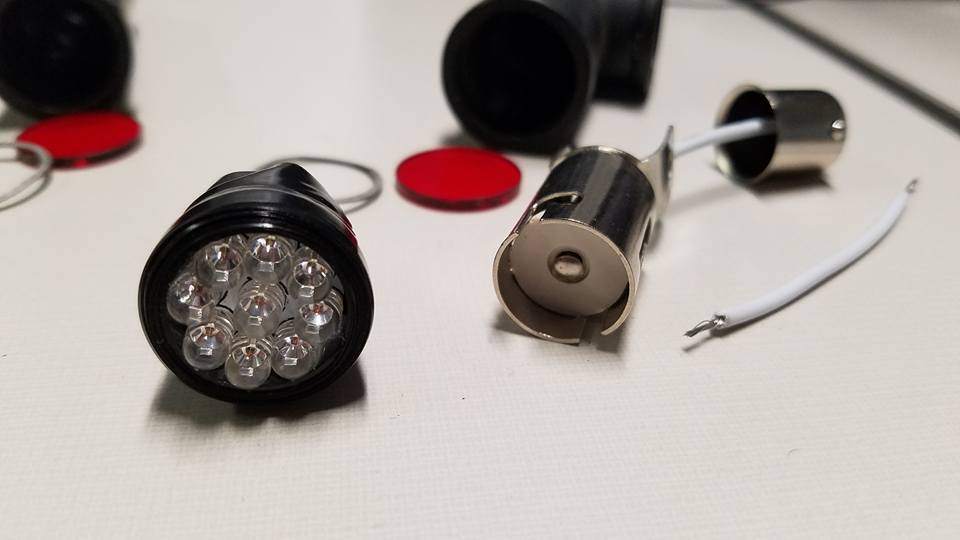
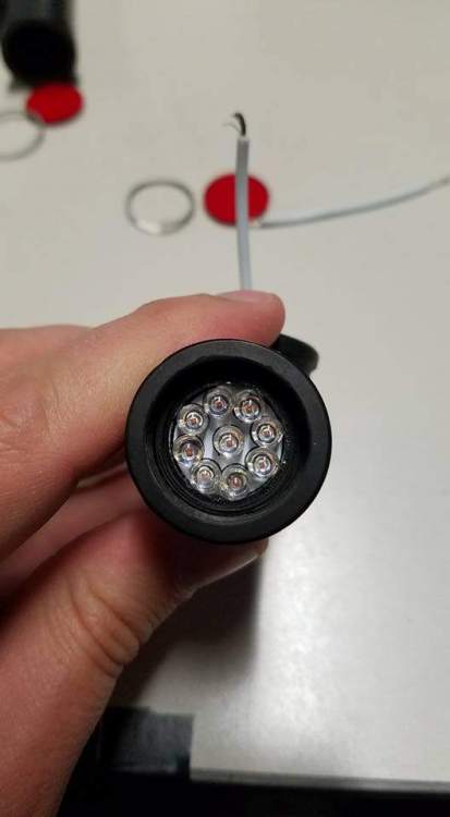
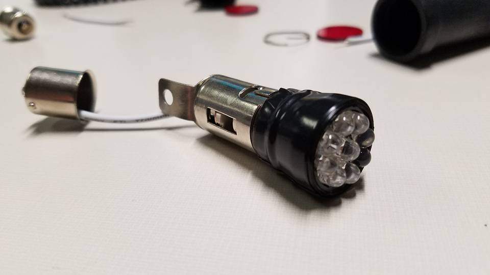
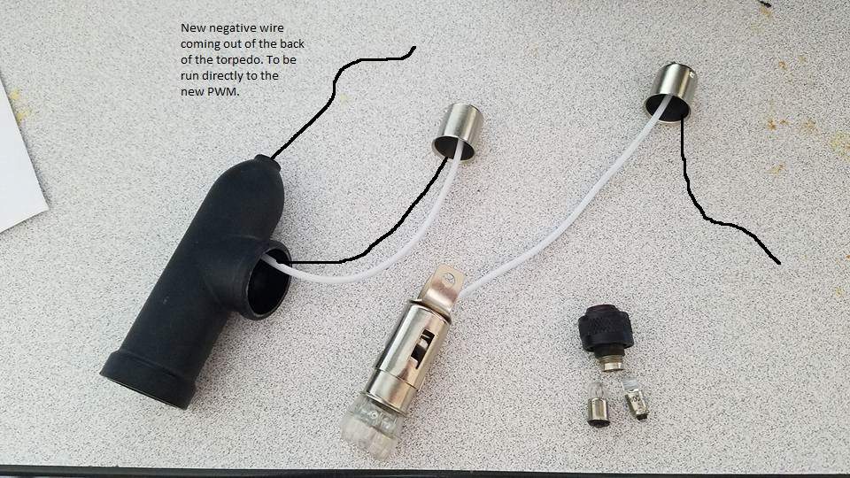
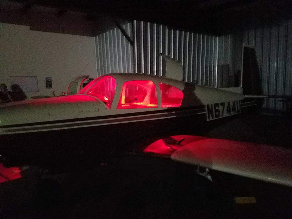
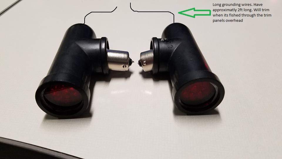
I did this a while ago but seem to be getting a lot of private messages on finding it, so I've consolidated the pictures and will be making a "how-to" in its own thread which can be searched. This is a purely informational post about the possibilities of LEDs and is tested on a grounded aircraft and is no way airworthy pending your IA, local FAA DAR, or 337 modification. This requires rewiring and removal of the old overhead rheostat that controls the lights. Approx time to complete: 2-4 hours. |Approx cost: $50 Parts needed: (I ordered my parts from SuperBrightLEDs.com, but some of these have since gone out of stock. You will need to source them elsewhere) Note: The wiring layout in these pictures is incorrect when I took them. I later rewired them. I have edited the photos that needed new wiring since taking them. Refer to the final wiring diagram at the bottom of this post. 2x BA15S Empty Bases (BA15S-EB) 2x BA15 1156 wired sockets (BA15S-SW) 2x BA15/1156 LEDs (67-R15) LED PWM Dimmer (Oznium makes a great product that is small enough to fit where the old one goes) Soldering Iron Solder Electrical tape Knife or another pointed object Wire strippers/dikes Thin (20+AWG) wiring approx 2 feet 1.)Pop the existing torpedo's off the stock lamps by gently pulling them off. Twist and remove the 1156 bulb. 2.) Using a knife, gently pry up one end of the retaining clip holding on the red lens. Remove the red lens. 3.) Turn the focusing ring counterclockwise until it stops. Using a pair of pliers, grip the twist knob and continue to turn counterclockwise. You will feel resistance, you will be ripping apart the solder holding it to the clip inside. *THIS WILL RESULT IN PERMANENT DESTRUCTION OF THE OEM FOCUSING LENS*. Once it is broken off, tap the insides out. 4.) Now that everything is disassembled, clean everything good. You'll have 50 years of crap over everything. 5.) Using the electrical tape, wrap it around the 1156 bulb about 8-10 times. Keep test fitting in the housing, it should slide back into the torpedo and fit snugly. 6.) Bend the two tabs of the wired sockets back about 85 degrees. You want a little bit of flare in them as they will press against the inside of the case to hold the fixture in place. 7.)Solder the positive 12v+ lead into the center electrode. Add some solder to the inside of the empty base and attach your 22AWG wire to that. Leave about 2 feet of dangling wire as we will need to fish through the overhead panel. Insert the soldered base into the torpedo, fishing it out through the side hole. Run the (-) wire out of the back of the torpedo. Slide the rest of the LED into the unit, and reinstall red lens and clip. Put the units back together and they should look something like this. I recommend having another 4-5 inches between the torpedo and the base socket. These were ultimately too short as you have to twist-lock the bases with the torpedo out of the way before you slide the torpedo back onto its mount Now for the hard part. (Again, please have an A&P handy for this if you are not versed in 12v applications. Of course, this is not a legal modification for flying aircraft and appropriate documentation and paperwork needs to be filed before flying). I don't have any pictures of this process but its simple once you see what I am talking about. You'll need to drop the overhead trim panel and find your old rheostat. Remove it but carefully identify which wires are which. You should have a positive and negative ship input, and one positive output (the factory map lights are grounded at the sockets. We cannot have that- they need to be grounded at the PWM hence the new wire). Remove the old rheostat and install the new one. Run factory wires into the INPUT terminals of your PWM. Run the factory output (+) wire into the appropriate terminal. Fish your 2 foot long ground wire through the steel roll cage and all the trim pieces, and then trim it down and attach to the PWM. Flick on the master, and with the PWM in the OFF position, nothing should happen. If the LEDs come on full brightness, they are prematurely grounding somewhere else. Turn the rotary dial on. It has a duty cycle of 5-100% variable and the LEDs should correspond. If this works, you have completed it. Put everything back and enjoy. (In the following pictures, I also changed out the cargo compartment dome light with a simple 3156 LED that replaces the old bulb. This is full-brightness output and can be dimmed by 95%). Any questions, feel free to PM me. -Alex
-
Dear Friends: On Tuesday, I flew my 1966 M20C Mark 21 from Fort Leonard Wood, MO to Louisville, KY (actually Jeffersonville, IN because I couldn't get into Louisville VFR despite extraordinary assistance from the Louisville Approach controller, but that's another story...). Anyway, I used both radios (King KX 170B and KX 175B TSO) on the way out and most of the way back, but after the final handoff for continued flight following to my home airport, I couldn't contact Center on either radio, but I continued to receive just fine on both radios. Perhaps unrelated, after sunset, I turned on the twin cabin ceiling red lens spotlights which illuminate the instrument panel, and when I rotated the on/off rheostat knob to the full stop brightest setting, both spotlights flashed off simultaneously. Subsequently, the single white light cabin ceiling light failed to illuminate when I tried turning it on. It worked fine the last time I used it a few weeks ago. None of the circuit breakers popped. The filament in the single, panel-mounted fuse appears fine. I found three (there may be more) wire-in-line fuses under the instrument panel. Each appears to have a spare fuse taped to a wire adjacent to the fuse in use that it is apparently intended to replace. I need to return my daughter to Jeffersonville, IN (her car is parked there because of my diversion from Louisville to Jeffersonville) on Tuesday, and really would like to have a least one operational radio for such a long VFR flight. The cabin lights are less critical and time sensitive. What's the most likely reason for both radios to stop transmitting simultaneously, yet continue receiving just fine? Are the cabin ceiling spotlights and the cabin ceiling dome light on a shared electrical circuit with a fuse located under the instrument panel? Thank you, Bobby (573) 337-3447 Sent from my iPad
- 6 replies
-
- KX 170B
- KX 175B TSO
-
(and 6 more)
Tagged with:

