

ed
-
Posts
13 -
Joined
-
Last visited
ed's Achievements
")


-
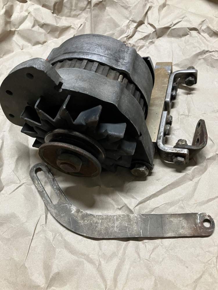
Selling used alternator setup removed from m20C O360 wide deck. It was working when removed Oct 2016. Replaced it because CB had tripped twice in two months or so. Finally found the issue when it was all being removed, there was an unshielded ground wire under panel that sometimes vibrated over and caused a short. Was not the fault of any of the parts, but had already purchased replacement system so installed it. InterAV PN 015-01237 12v. 50 amps SN 625-61623 new 9-1996. IRAN by interAv 1-16-2008, had new brushes installed and a new regulator SN 14125 purchased. Has 300 hours since then, about 1100 TT on it. Comes with manual and over voltage parts has mounting brackets, apparently a narrow deck bracket adapted to mount on wide deck engine. Asking $500 OBO. Baffle rubbed on case so rubbed part of label off.


-
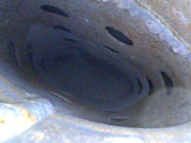
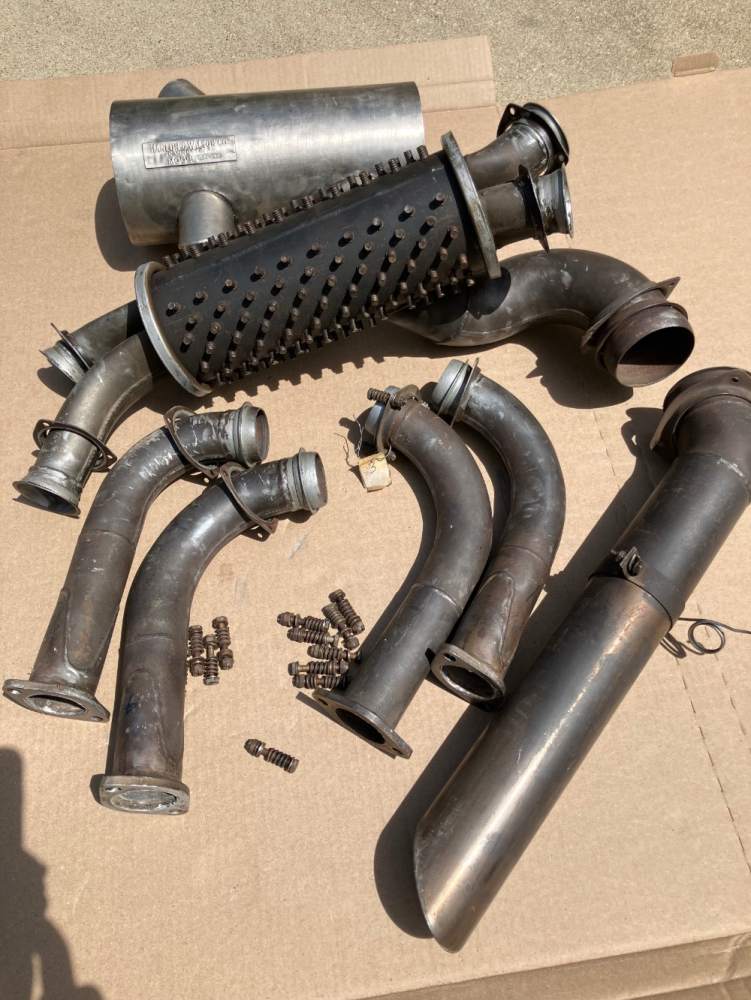
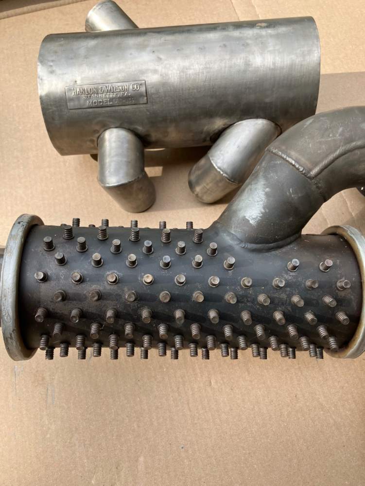
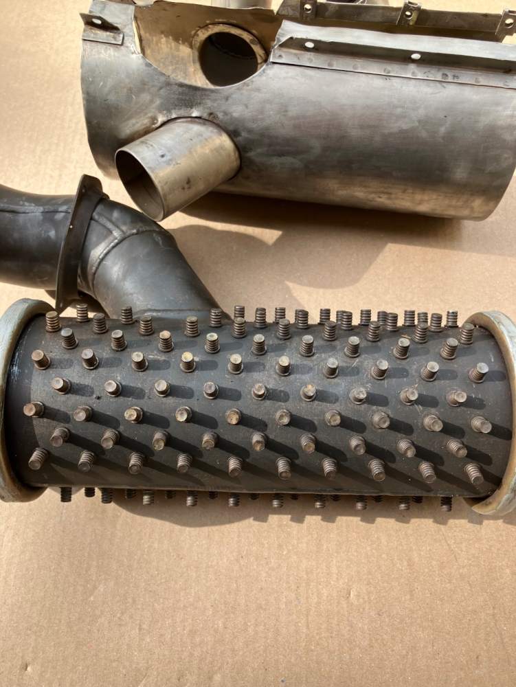
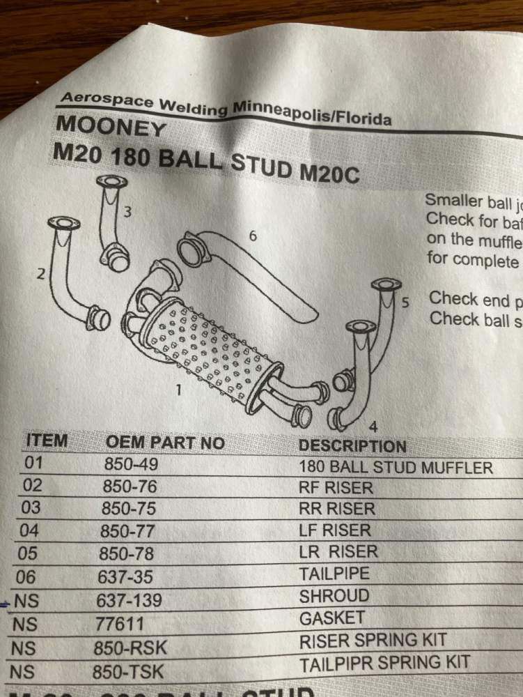
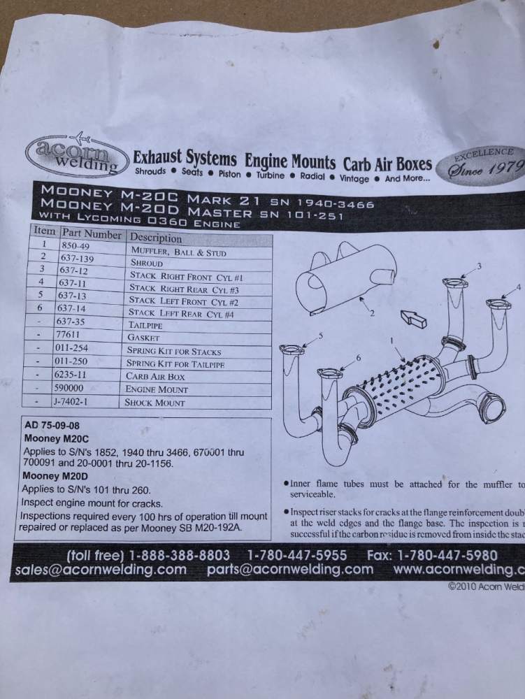
Here are 4 pictures of the flame tubes, one picture of each intake port in the muffler
-
Sold my m20C last year, had this for a spare, stored last 14 years. In excellent condition. For lyc 0360 180 hp. See two different exhaust pictures vendors fortheir part numbers. Asking $1500. Located central Texas. Flame cones look ok, can get some bore scope camera shots if needed


-
Hank, as noted in my post, this fuel selector is only used on the B's and early C's & D's. See the SN's there. If you have a 1970 C, that is likely the later style fuel system which is much different (has the pull chain drain/sample). I wonder if this early style is just a stainless steel ball and spring seat? Thought some here might know. Mine was dripping a little after taking a sample, but I took a few more and it stopped so maybe just a bit of grit under whatever type of seal it uses.
-
Anyone know what type of seal is used under the quick drain of fuel selector valve 6152? Parts book only shows the valve number. It was made by H&E. The drain is the type you have to push a metal rod up into that small pipe to drain it. here is a picture of it from bottom. There is a full valve like it for sale on ebay (BAS sales) for more pictures. I will have it apart later in month but would like to have the seal on hand. This is used on early B's and C's (SN 1701-2622) D's (SN 101-200)

-
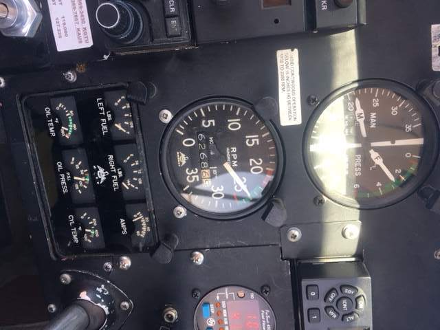
I dug out the POH , it shows to only use electric boost pump for takeoff so the factory apparently saw no need for it on extended climbs. I will show 4 PSI on ground. Near 0 on full power climb. At lower power curse, at 4500 or 5500 (forget when this pic was taken), fuel pressure shows about 2.5 psi, at 22 inches MP and 2400 RPM. So that is in the normal green range. So all that seems normal. JPI fuel usage showed 11.0 gal, and it took 10.4 gal, all from left tank. I did the self adjust method to tweak the K factor, as it is still reading a little high on 1.3 tach hours. not sure why the picture gets rotated
-
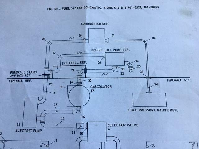
Well, the other place where fittings could restrict flow would be the T at 28 and the inlet to the carb at #30 in the drawing. I am quite sure I saw no restriction at the T, I would have to pull the hose off the carb at 30 to check that.
-
47U, I realize now that, with the fuel transducer in fuel line #29 in the picture I posted, that it ONLY measures fuel going into the carb. So even if some fuel was back flowing thru the electric pump (with it off) that would NOT affect the JPI FS450 fuel flow. As an aside, my fuel flow over the last few years was always showing high by about 9% when I did the re-calibration math here at annual. So I have adjusted the K factor. I just need to do some longer flights to see if it is more accurate now. It use to be off about 1 GPH so maybe read 3 gallons high after a 3 to 3.5 hour flight. I had left it that way on purpose as it was "conservative" as there was always more fuel left in the tank then than what the FS450 would show. It should be closer now with the adjusted K factor. I also found in the manual the FS450 can adjust the K factor at each fill up automatically, but you have to go through the right sequence of steps on the power up of it to do that.
-
Hammdo, I looked at the log pdf you posted. I know for certain that the two fuel pump fittings (in and out) of my mechanical pump (same PN as you have) do NOT have any restriction. They are stock "fuel pump fittings" that you can see on ACspruce if you search for that in quotes. Mine has a 45 degree into the pump and a 45 degree out of the pump. I also installed two new teflon hoses from PHT in Tulsa. I know restrictors are put on the fuel pressure fitting and oil pressure fittings as those don't flow any fluids, they just fill up and indicate pressure and if one of those hoses break then you don't want a lot of fuel or oil pumping overboard, so most have solder with a small hole drilled in them. But no reason to have that in the main fuel lines. I think the low pressure 4 PSI pump just results in a low reading at high power (max fuel consumption) and with the nose up high for climb it has to do more work to pull the full. I need to find my POH (its in the plane) to double check, but it likely recommends boost pump on for climb. I kind of avoid using it as it does bypass the gascolator (partially as some fuel likely going thru there and the mechanical pump and the extra thru the electric boost pump). I was mainly looking to see if others see similar pressures in climb on these carburetor engines.
-
I have a 1963 M20C (a D that was converted to a C just after leaving factory). 180 HP, carb so the Low Pressure mechanical fuel pump (4 PSI). Mechanical pump holds 4 PSI in level flight. In full power climbs FP drops to near zero on the gauge but engine runs OK. If I turn on the electric boost pump on climb, then pressure is higher, but not quite the full 4 PSI. On ground electric pump holds a full 4 PSI as does the mechanical pump. Also seems like it uses more fuel thru fuel totalizer than actual. I put on new mechanical pump and did not change anything. I am wondering if fuel could be going back thru the electric pump into the tank? See picture. This is the fuel system on B, C , SN 1701 thru 2622 and D SN 101-200. Its an odd design, in that the boost pump path bypasses the gas-colator. Also I don't see any check valve to prevent fuel from going back thru the electric pump. So the elect pump must have some internal flow back restriction method. Item 11 is a short fuel hose. You can see that the T on the firewall connects the electric pump path and the mechanical pump path. I think it has always been this way on the pressure but was curious what others see. Only way that fuel could go back into tank would be if whatever device is in the electric pump to prevent flow back is leaking.
-
NTSB preliminary report. note that both wings were folded up prior to impact. Also “ A 6-inch section of the main wing spar upper cap splice was found about 300 ft southwest of the accident site.” That seems to clearly show main spar failed at center section well before impact
-
BTW, you need to look at the valve lifter faces for any pitting (called spalling), very common on Lyc. The second from rear and second from front lobes are the worst as they operate two of the lifters so are very stressed. Also run your finger over the cam lobe as you can feel any bad lobe easier than looking at it. Also, be vary careful you get the rocker arm's back on correctly. The exhaust rockers are "squirters" as they squirt oil onto the exhaust valve to cool it. The intakes don't squirt oil (not drilled thru). If you mix them up then you may suck oil in thru the intake valve guides and burn up the exhaust guides. Believe me, I have seen A&P's screw this up. I know its that way on all the parallel Lyc, so should be similar on the angle valve (200 HP) version.
-
You should be using the mooney manual and follow the directions there on how to reseal. All the sealants can be obtained from SealPak directly in Wichita KS See name/number below. There are multiple products needed, two types of sealant, separate sealant (removable) for the access doors, and the top coat of latex. Get the stripper from RPM Technologies in NJ. Its great stuff, called polygone if I recall, does not burn and is designed to strip the polysuffide. The right tank is the hardest due to more doublers for the wing walk inside the tank. I have all the notes at the airport, but that's what I recall. SEALPAK CO INC (316) 942-6211 2614 S Hoover Rd Wichita, Kansas 672151299 , USA
