

Wingover
-
Posts
152 -
Joined
-
Last visited
Content Type
Profiles
Forums
Blogs
Gallery
Downloads
Events
Store
Everything posted by Wingover
-
My electrical guy (not available for a few months) said there is an amplifier (my J is 28v) like this one: Mooney M20J TRANSDUCER AMPLIFIER P/N 950D0311-001 - 800331-984 FUEL PRESSURE AMP | eBay Here is the wiring diagram:

-
@PT20J I can confirm that I have the RSA fuel servo. I also checked the voltage, and I have zero. A couple of days ago when I checked (while the transducer wires were connected as well), I saw 7v between the red and black but noting today. I understand that there is an amplifier between the gauge and transducer. Not sure how to check that....
-
That’s $25 per hour flight…. For a part that probably cost them $20 to make? I get that it’s aviation and unique part but $2550 ??
-
I’m wondering if leaving the mixture and throttle pushed in after shutdown can eliminate the pressure spike?
-
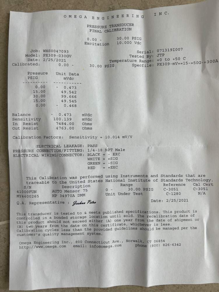
I am not sure where you see the 3x safety margin. The link you provided is the 0-100 PSI transducer. Looking at mine (30 PSI) I could not find the info.
-
I have a rebuilt engine but pretty sure it's RSA. I will be doing oil change tomorrow so will check again and let you know.
-
I believe I have the RSA servo. It is interesting you mention that. The Omega tech support asked if there was a way to build pressure above 30 psi since that will kill the transducer.
-
Thank you @PT20J as always! Could you please look at the attached and help me identify the pin numbers based on the wire colours?
-
Hi All, My fuel pressure sender in my 1987 J stopped working a while ago so based on the reading here, bought the Omega (model PX309). It has worked fine but after a couple of months I noticed that it would not work or start fluctuating until it stopped completely. I checked the wire connections between the sender and harness going to the panel and it seems fine. Can someone tell me how to check if it is the sender, amplifier, broken wire or gauge?
-
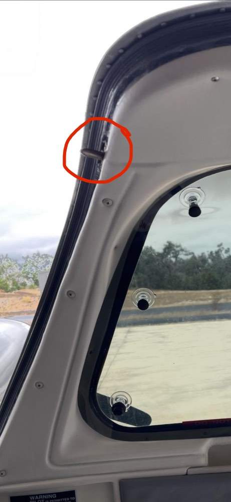
Looks like the bushing (guide) the rib is worn or missing?? Sometimes the tube might have a wrap around it for protection..
-
Pictures of Newly Upholstered Seats
Wingover replied to Speed Merchant's topic in Modern Mooney Discussion
Mine….

-
The only difficulty I had was holding the seal in place on the forward part of the door, it kept sliding off. I managed to keep it in place after all. Doing an oil change so won’t get a chance to fly it until next week.
-
Finished mine

-
@LANCECASPER I just noticed that your door has a pin on the front side..see picture. My 1987 J doesn’t have it. What model was yours?
-
Hi @tomgo2, Is it possible to get this (maybe PDF) by email or DM? I am not sure if I am missing the lower right part of your picture. I see the number 5 as 22" distance to where to drill but also see "5" at the bottom right of the picture but the rest of it is cut off.
-
Thanks! Hoping others might have more information or pictures if the install (especially the grey hose)
-
Sorry, I am talking about the little grey piece tube that is part of the seal itself. It has to somehow go inside the door frame.
-
Looking for help from people who installed the Bob field seal on their M20J. I am specifically looking for help on where did you locate the little grey hose (that connects to the pump hose) that is part of the seal? Did you locate it down below the part of the door or on the side (closer to the hinge side)? Do you need to drill a hole to route it into the door? Any help would be greatly appreciated. Understand how to glue it and how to trim the plastic door cover if needed for space.
-
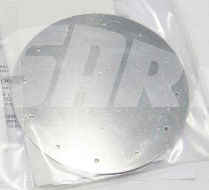
Yes, I have no problem with Fiberglass work (used to do it for a living) I was just curious if the aluminum round plate was meant to fit into the rivets holes of the ram air intake that will be removed. I guess it is not I will fabricate a slightly larger one to go over the old main intake hole and rivets holes.
-
Does anyone have the dimensions (diameter and thickness) and hole spacing for the ram air delete plate? Lasar doesn't have stock but I can have a machine shop make one for me, just need a drawing or specific info. I attached a picture of the plate.
-
Just educating myself to make sure I understand the process. Used to gap the points and adjust car engine distributors so I have an understanding of the mechanism but new to aircraft magnetos.
-
Thank you. When my engine is set (on the #1 ) at 25 BTDC with the flywheel and line between the two engine case halves the letter L (not K) is lined up with the mark on the top of the magneto and I can see the red line in the side hole.
-
Thank you for that and the link. It’s what I was after.
-
Thanks everyone for the replies. I was more curious as to what the letters are on the top hole. I tried looking for the manual online but the ones I found do not talk about that. I understand that the same mag can be set internally for the 20 or 25 engines.
-
Trying to find the info on setting timing on the dual mag. There are a few letter like "L" in the top hole of the mag and the side hole that shows the red mark on the gear teeth. I am reading the it should be the letter "K" on top but can't verify. Does anyone have any pictures/instructions and what letter should be aligned on the top hole when the 25 degree mark on the back of starter ring is lined up with the top of the engine case halves while the #1 is on the compression stroke?

