

kinser
-
Posts
16 -
Joined
-
Last visited
kinser's Achievements
")


-
Good point. I swung by a nearby MSC today that mentioned some of the same points. Their suggestion, and my next step before replacing anything will be pulling out the interior panels again watching the backside of the window for water coming in while my poor wife pours water on the bits that might be leaking. Hopefully that would be a pretty direct way to see and identify the area... possibly allowing for a patch instead of a replacement.
-
Is this the stuff? The b2 / red variant? https://skygeek.com/flamemaster-cs-3330b2-sealant-6-oz.html
-
BWAHAHAHA!!! Just goes to show the value of this forum... I tried so so many other places and finally found my answer in a can of CS3330.
-
I do love working on things myself, but given the need to get this done fast, I will almost certainly end up hiring someone to do the work. I mostly just wanted to get an idea for the level of effort involved to see if it was even within reason... the posts on some other / older models makes it look waaay more involved. I've got a couple MSC locations within reach, so I'll ping them to see what it would cost and if they aren't available, then I'll be going to see @jetdriven in person.
-
Thank you!!
-
Does anyone know the process for replacing the rear windows on an Eagle or Ovation? I've been able to find posts about doing this work on other models, but the design is certainly different on those. I've got a water leak on my rear and am debating on just replacing the entire thing with grey / tinted units instead of the clear that is currently there.
-

M20R / M20S Boost Pump Regulator Voltages
kinser replied to kinser's topic in Modern Mooney Discussion
Hey @Dominik_B -- there are two components there, the rectifier (2 legs) and the bipolar transistor (3 legs). I'll link to the ones I used below. And just in case someone is reading this years in the future and the reseller has removed their product pages, the rectifier is MUR1540G and the transistor is 2N6668 PBFREE. https://www.mouser.com/ProductDetail/onsemi/mur1540g/?qs=Gev%2bmEvV0iZq6LchZ03NqA%3D%3D&countrycode=US¤cycode=USD https://www.mouser.com/ProductDetail/Central-Semiconductor/2N6668-PBFREE?qs=l7cgNqFNU1ijRYXR1DLWNQ%3D%3D&countrycode=US¤cycode=USD -
M20R / M20S Boost Pump Regulator Voltages
kinser replied to kinser's topic in Modern Mooney Discussion
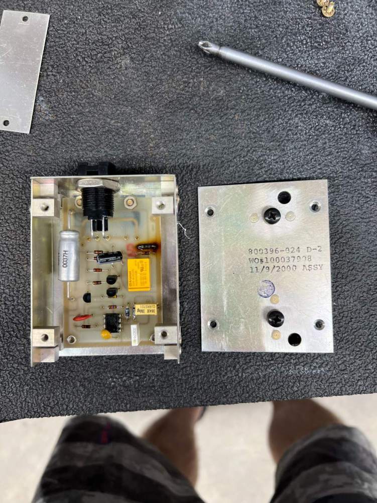
Oh don't worry, there is a rebuilt unit from an approved shop on the way for the actual aircraft. I just couldn't see a board that looks this straightforward and not try to resolve it. The pump itself is rated at 28v, which it gets when the high boost rocker switch is activated. This regulator is just used for low boost, hence the need for the lower voltage to achieve a lower output. Oh it's definitely a regulator. The transistors are on the backside. It kind of looks like what I would make for science projects in high school. And not just the board itself, but also the box containing it. It looks just like what radio shack used to sell as "project boxes". You hit the nail on the head with regard to the low vs high boost aspect. As for the transistors, they're mounted on the backside of the board and use the metal case itself for heat dissipation. That design does make things cumbersome though, because the transistor cannot ground to the case, despite mounting to it. So they couldn't use normal thermal paste for the backside of the transistor and instead has to use fiberglass based thermal pads and plastic screw insulation shims and mounts. It seems... sketchy. Ah, so no set voltage, just whatever is necessary to achieve to desired pressure. Thank you!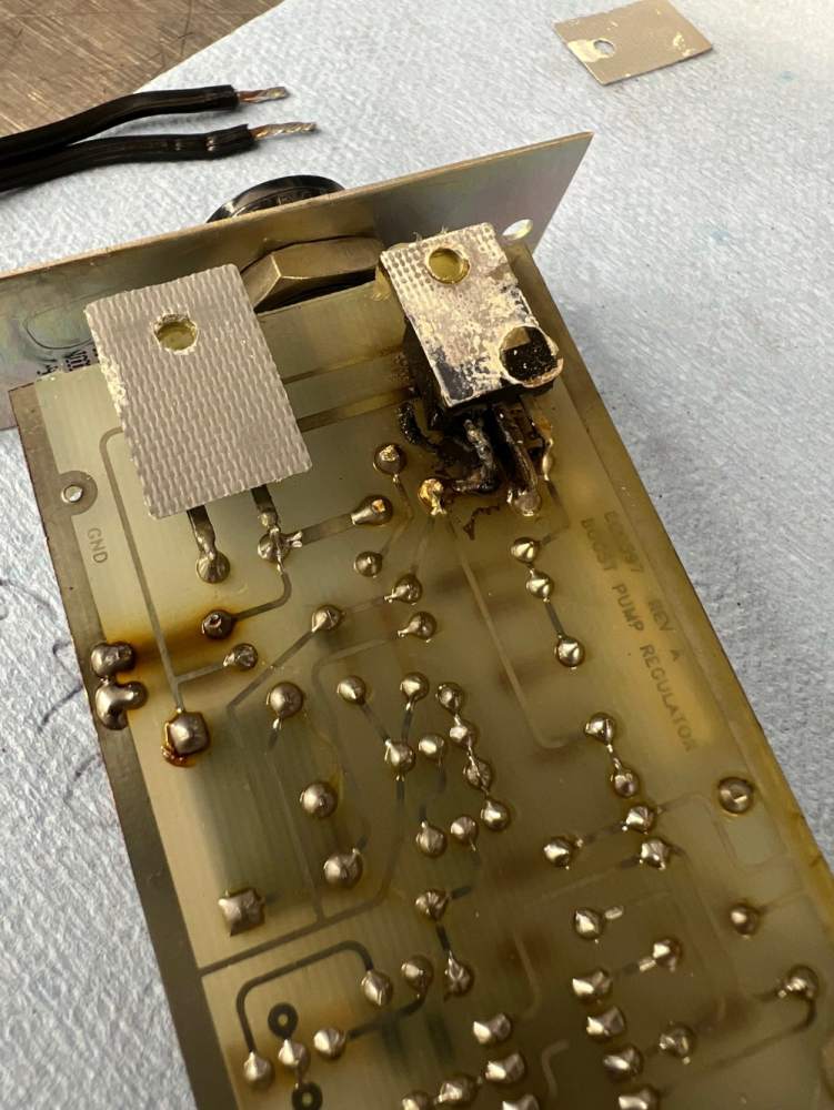
-
Recently had a boost pump regulator go out on me and just replaced the blown diode and transistor to get it back up and going. I'd like to sanity check the voltages coming out of the regulator though... what is considered normal from an output perspective? It is all adjustable via a trimmer potentiometer, just wondering where to start.


-
I've got a close friend (non-forum member) that is very interested. He has seen my M20S up close and personal a bunch, so he's got the Mooney bug. I'll shoot you a private message to get some contact info. We're based down in Charleston and can fly up to Rock Hill to take a look as early as this Friday.
