BrianW
-
Posts
64 -
Joined
-
Last visited
Content Type
Profiles
Forums
Blogs
Gallery
Downloads
Events
Store
Everything posted by BrianW
-
I just called Dodson. They haven't received a salvage M20J in years. None of their older scrap Mooneys have glareshields.
-
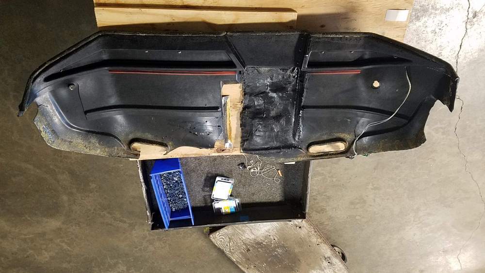
I think the glareshield was in the sun for many years before getting repaired and eventually covered in vinyl. The plane is a 1979 M20J. New glareshield from Mooney is over $3000, is a special order, and takes several weeks cuz Mooney has to fabricate them when odered (non-stocking item). Ashby won't work cuz my glareshield has the bump for the annunciator, and Ashby doesn't have the bumped up section for the annunciator I called a salvage place in Tennessee and LASAR. They didn't have used or new glareshields. I don't know any other salvage place for M20Js. Yes, the underside section is the light brow and the brow extends back to form the stiffener ribs. The brow and stiffeners are one formed piece of ABS plastic.
-
Hi, I have an M20J with a glareshield that's cracking apart. I contacted Hector at Aerocomfort and he looked my photos. He said it was beyond repair. Luckily he had a new M20J glareshield available. He previously covered it in leather for a project but now it was just sitting around. He offered to sell it, so I bought it. It looked great but didn't fit. It appears that it's about 1/2" to 3/4" long (but l guess all new glareshields need to be trimmed to length). But more importantly, the underside section is missing. The underside section is molded to stiffen, match the profile of the panel, and hold the panel lights. Without this underside section of the glareshield, there's a 3/4" gap between the glareshield and the panel. I contacted Hector. He said it didn't come with the underside section. I am thinking that I could make a mold of the underside section from my old glareshield. Then I can have a part vacuum molded to use in the new glareshield. Making the mold pattern from my old broken glareshield will be difficult and take time. Any tips, options, or advice would be appreciated. Thanks, Brian P.S. The first photo is the underside of my broken glareshield. The second and third photos are the new glareshield.


-

Engine recently seems to be leaking oil
BrianW replied to BrianW's topic in Modern Mooney Discussion
I really appreciate the comments about how normal belly oil is...and the good products for cleaning it off. Thanks ☺ -
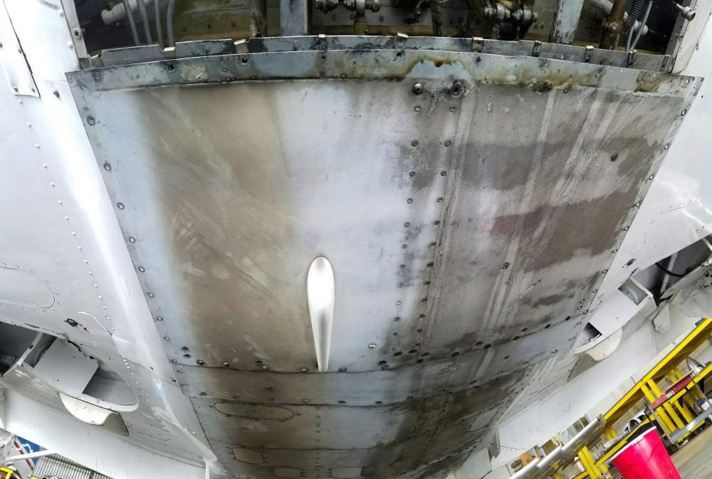
Hi, I have a 1979 M20J with a Lycoming A360 engine, approx 1000 SMOH. I have it serviced at a MSC. The oil is tested each time I have it changed and everything has been normal. However, since my last oil change last July to now the engine started to leak oil at cylinder 4 by the guide tubes and slight leak around cylinder 1 exhaust manifold. The lower spark plug on cylinder 4 regularly is oil fouled but I can clear it at run-up. At my tie down there are no noticable oil drip spot. The engine breather tube seems wet but that could be the oil dripping on the tubes from cylinder 4 above. The senior mechanic says the oil leak is very small and not to worry about it. This is my first plane and I've had it for 2 years. Coming from an automotive background seeing an engine leak oil bothers me. I keep my plane clean and now the belly has oil and exhaust marking. I've attached a picture of the white belly panel (looking towards the tail) before it was removed for its annual. The exhaust stain may not be related because the exhaust pipe was rotated a bit closer to the belly last annual since the exhaust pipe was interfering with closing the cowl flaps during flight. The exhaust pipe doesn't have much of a bend at the tip so the exhaust isn't blowing as far away from the plane as before. I am told the tiny amount of oil leaking at cylinder 4 isn't worth the estimated $1500 to have the cylinder pulled at this time. He suggests I add wiping the belly after flights for now (he said it was something he had to do with his 172). The mechanic and the shop know I don't have deep pockets. And this annual is going to be very expensive already with us replacing the old instruments with a JPI EDM900 and CIES fuel senders. I'm on the fence on what to do. Financially, I can't do all the work I want in one visit. I prioritize the things that must get done over the things I want to get done. I then I do the tasks that need to get done, and if funds allow, I'll tackle a few of my wants. With the JPI, I hope the I can more accurately lean the engine to prevent running rich, which may help with the exhaust stain (perhaps even help with the oil consumption).
-
Garmin or Aspen EFIS options to work with Century Autopilot
BrianW replied to BrianW's topic in Modern Mooney Discussion
Or perhaps I need only the one G5 connected to the GAD29B. Maybe the single G5 provides both attitude AND directional info to the GAD29B to output to the Century 41. -
Garmin or Aspen EFIS options to work with Century Autopilot
BrianW replied to BrianW's topic in Modern Mooney Discussion
Hi All, Some added info: My M20J doesn't have a flight director. It has the common Century attitude indicator and directional gyro (not an HSI - my mistake in the initial description). The GAD29B has 2 input ports to which the G5 units can connect. I assumed my autopilot receives it's input from my current directional gyro via the heading bug for my heading. And my AI provides attitude input. I'm not sure how the Century 41 receives altitude info. However I thought the G5 in HSI mode would provide direction and the second G5 would provide the attitude input. I assumed I needed the two G5 to provide input to the GAD29B, which processed and provided output to the Century 41. I need to look into this in more detail to see if using the Garmins would reduce functionality of the Autopilot. ☺ -
Hi, I have a 1979 M20J with steam guages and factory installed Century 41 autopilot. When the time comes, I'd like to eventually upgrade my attitude indicator and HSI, but the AI and HSI provide output to drive the autopilot. One EFIS solution may be the Aspen E5 with ACU which can output to legacy autopilots for $5995. The other EFIS option is to install two Garmin G5 units (one set as AI and the other setup to display HSI). My preliminary research led me to believe installing the new Garmin GAD29B module provides autopilot legacy output for my autopilot. The Garmin G5 primary set as AI costs $2149, the G5 primary set as HSI with the GAD29B costs $3154. The 3 unit Garmin setup totals $5203. Is one better or preferrable over the other? Aspen has cleaner installed look The Garmins can provide redundency for each other. Both are well established trusted vendors. I'm not sure about the installation time and cost for either option. Its hard to find reviews that compare the Garmin vs Aspen configured to be equivalent (an apple to apple comparison). I'd like to know the estimated difficulty and installation time for both options. Cost of owning, maintaining and upgradability is important to me. Which setup would you choose and why?
-
I agree with you whether it is 4130 or A36, the steel would probably be stronger than my foot could bend. However, the 4130 material is specified right on the drawing for the pedal extension. And 4130 is significantly stronger than common A36 steel. So I would have to use thicker A36 steel to be as strong as 4130. I could calculate it how much thicker it would have to be to be equivalent to the specified part, but why when 4130 could be bought. I found a metal supplier that had 4130 1.5"x1"x0.065"wall. Simple-trace-cut-drill-paint and match Mooney spec easily. I can then proove my owner-made part is the same as Mooney's to my A&P or anyone else. Otherwise, if I or someone else crashes and the impact bends the pedal, I don't want some investigator saying the owner-made-part may be inferior, and possibly then blame my part for the cause.
-
I could build a set but I would prefer the precision of using 4130 structural tube 1.5" x 1" with 0.065 wall and cut the one part out - rather than use sheet and try to make 2 parallel folds. I tried to do the folds and was a 1/32" too wide. A lot of work to toss out and using tube having the perfect 90 degree bends with a 1.5" width would be infinitely easier. Unfortunately, all the steel suppliers are out of the 4130 tube till at least November. I'd sure appreciate it if someone has or knows who currently has stock of a foot of 4130 structural tube 1.5" x 1" with 0.065 wall available. Otherwise paying more to buy a used set of the 3" pedal extensions is the next best option for me.
-
Hi All, Again, if anyone has the 3" pilot extensions and wants to sell them please let me know. ☺ Thanks, Brian
-
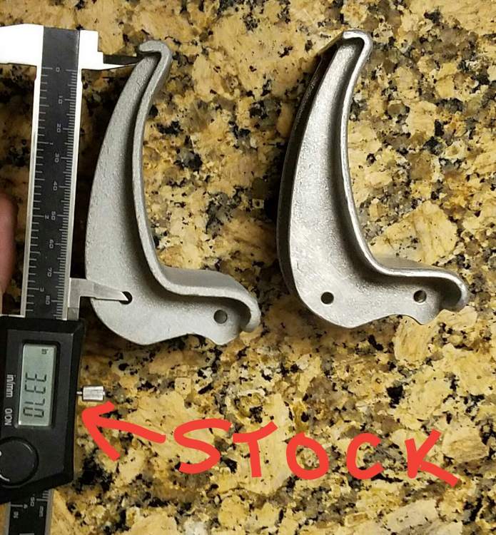
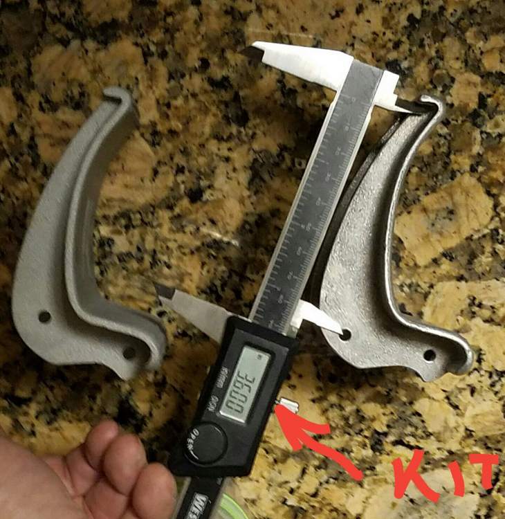
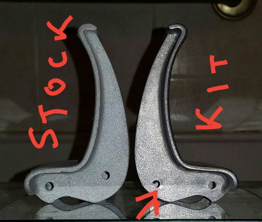
When I bought the Mooney copilot kit, it came with the new pedal all parts and drawings. The difference in the mounting hole location is 3.600 - 3.370 = 0.23 inches. Almost a 1/4" lower, which relatively speaking tilts the angle at the top back, as compared to re-using the stock pedal.
-
Hi John M, I was wondering if you used the 3" extensions with your stock pedals? If you did, that would explain why the top of the pedal is angled down more. Mooney's 3" kit includes new pedals with the holes in different locations from the stock locations (see my photos above to compare side by side stock and kit pedals).
-
Hi Ragsf15e, If it turns out you have the 3 inch pedal extensions, and you are going to remove them, I'd be willing to buy them. Because now that I installed extensions on the copilot side, I'd like to install a set on the pilot side as well. Thanks, BrianW
-
Looking for input to modify Mooney for short copilot
BrianW replied to BrianW's topic in General Mooney Talk
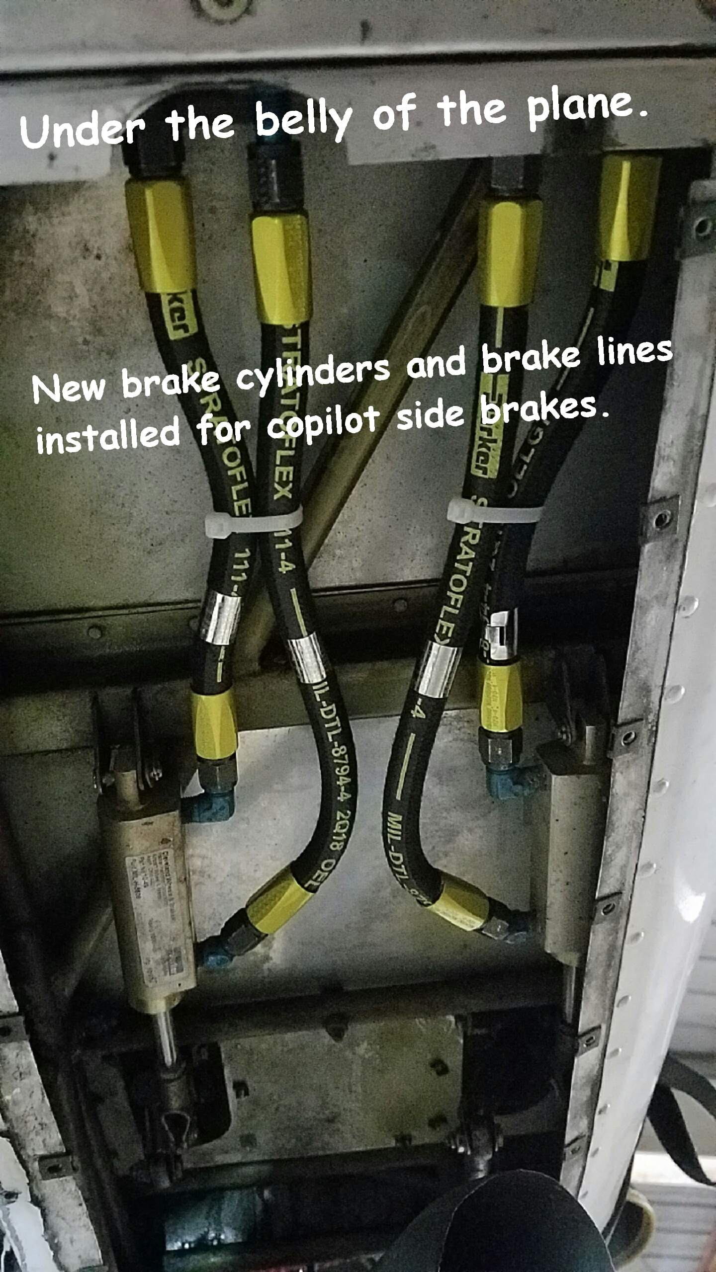
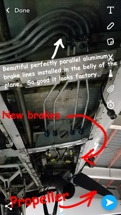
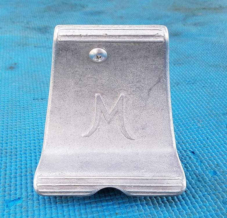
Hi All, I was able to buy a complete copilot brake kit used for $450. I installed the brake kit under supervision of my A&P. For me the most time consuming part was the bending and forming of the 4 metal brake lines to be perfectly in position, parallel, and straight...looks like a perfect factory installation. LASAR had a sale on the 3" copilot brake extension kit for $250 each, so for authentic Mooney parts, I went for it. NOTE: Mooney brake extension kit includes new pedals! Yes, they are cast the same as stock pedals. But the hole for the brake linkage is drilled in a different spot (see photos). Changing the hole location changes how the pedals align and mount in the Mooney. Building the extension brackets yourself would require you to either accept toebrake pedals shifted more aft - meaning you could accidentally depress the brakes when you are on the rudders, or you would have to know how to reposition the holes in your fabricated extension, and if you did then they would not match the original part specification. So $250 with a new pedal seemed like a good deal. Since, I was doing all the work, rather than reuse the original copilot rubber hoses, I decided to install new rubber lines. And if I'm ordering new rubber lines for copilot, it seemed a good idea to replace my old rubber pilot side brake lines as well. After installation, I left it to my A&P to do the adjustments and testing to the new brakes. They look and move great. I can't wait to see how happy my wife will be when she can reach the pedals and be able to stop the Mooney. Now if I could only find a reasonably priced articulating seat base. Brian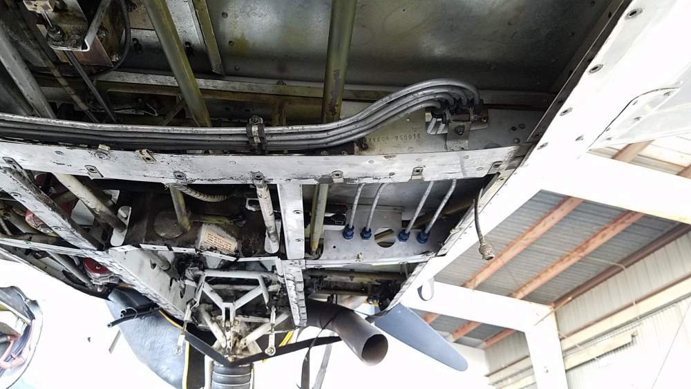


-
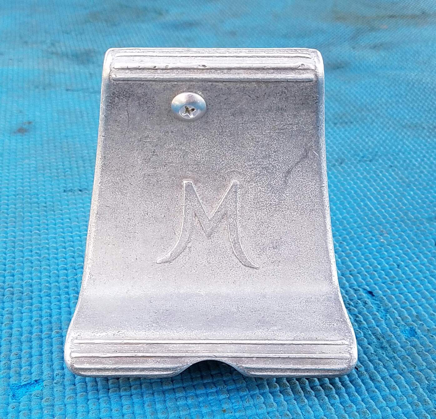
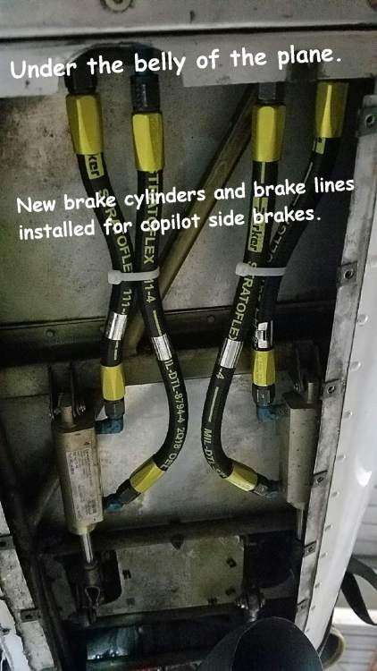
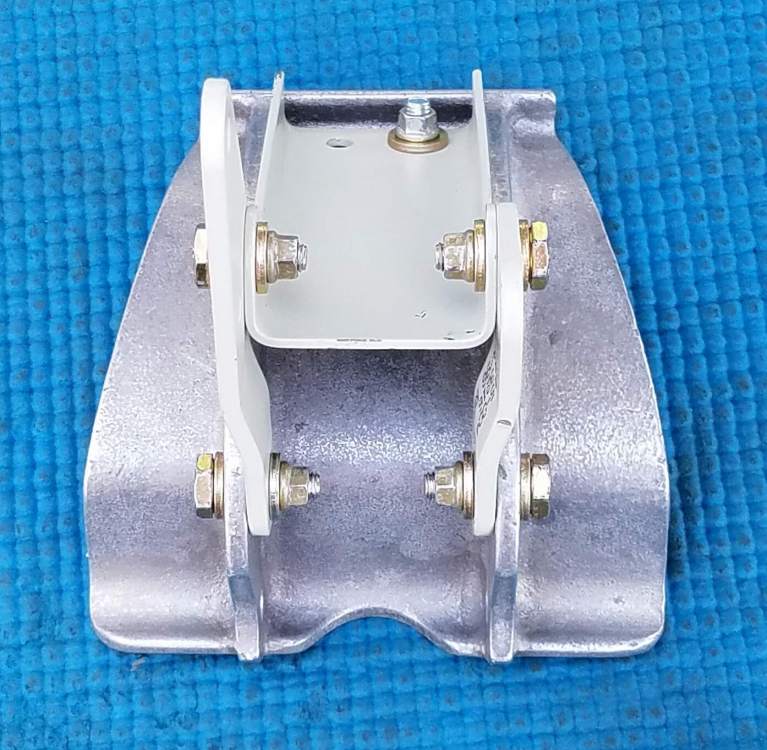
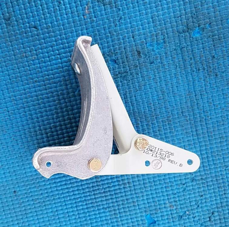
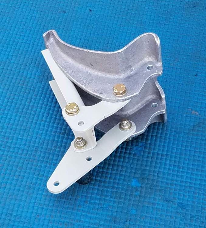
Here are the front, back, oblique, and side view of the assembled extension assembled on the new kit pedal. Notice in the side view that the mounting holes are in a straight line with extension bracket holes.


-
The drawings are good to produce the parts but the pedal supplied in the kit is different from the stock pedal. It is from the same casting but the rear hole location is slightly lower (see photos). You'd have to redrilled a lower hole or shorten the c-channel link. Otherwise when put together on the stick pedal the angle of the brake would be closer making it easier to accidentally apply pressure to brakes when you want to be off the brakes. Brian


-
Looking for input to modify Mooney for short copilot
BrianW replied to BrianW's topic in General Mooney Talk
Thank you guys for the helpful info. Yeah, I am leaning towards augmented cushions. I think I'll find upholstery foam and shape it to match the contours of the current seat. Then I'll upholster them into a seat cover so they stay put and match the interior. As for the rudder pedal extension, the copilot side doesn't have the break pedal linkage. It is a simple tee bar. I could make something that fits the simple cross tube of the copilot rudder pedal, but I prefer not to reinvent the wheel. I'm sure there must be an easy proven solution but I couldn't find any image for the brakeless copilot rudder pedal extension anywhere. I even looked allover Lasar and couldn't find an image. As for the midget comment, nope she isn't. She is simply a petite woman. But she is at the tiny end of the spectrum when compared to the size of the normal European man-size that the plane was designed around. -
Hi all, My wife and I wanted to learn to fly and get our own plane. She thought it would be great to visit all the States since we are trying to run a marathon in each State. Flight training for two people would be expensive. But we thought one way to reduce cost in the long run would be if we bought the plane we'd eventally want anyway, and take lessons in it, and not rent all those hours. She agreed, and we bought a Mooney M20J a little over a year ago. We really love it. I recently got my pilot's licence and my wife is getting close to completing hers (she's not using the Mooney for her lessons). My wife is 5'-1" and has trouble reaching the pedals. She'd like me to make adjustments to the copilot's side to fit her better. I see Lasar has an item "copilot side pedal extension". But since the copilot's side is just rudder and no brake, I'm not sure what a brakeless rudder pedal extension would look like? Does anyone have a picture of the copilots side rudder pedal extension? Another thought I had was, if I have to buy pedal extensions maybe for a bit more money for used parts I could modify her side to add copilot brakes. I think this would add value to the plane too. I've read in searches here that some have added copilot brakes using used parts. One question; are the pedals, arms, and linkages the same as the pilot's side? Could I buy a used set of pilot side brake pedals and mount them (with labor to add the attachment points) on the copilot's side? As for the seat, she needs 3 to 4 inches added to the butt and back. There doesn't seem to be an inexpensive way to get an articulating seat base, if one could be found at all. Any tips? My low cost thought was to buy 4" thick foam, and make seat bottom and back cushions. I'd sure appeciate hearing other's ideas and solutions. Thanks Brian
-
Help! Too much slack in the trim wheel chain
BrianW replied to BrianW's topic in Modern Mooney Discussion
My plane had about 3500 hours on the airframe. There were no specific entries regarding lube of the trim chain. However the old chain was lubricated and moved freely. Perhaps after the decades of holding the tail up and vibrating during flight, maybe it just became worn out. Thanks to everyone for their responses! Brian☺ -
Help! Too much slack in the trim wheel chain
BrianW replied to BrianW's topic in Modern Mooney Discussion
By the way, I was sent the drawings for the various parts. The adjustment does not move the gear box in a slot. It is simply an oversized hole that the gearbox can slide from upper extreme of the hole to the lower extreme of the hole (allowing about 0.1" of travel). The stock NAS adjusting bolt allows adjustment for the full range of travel. A longer bolt wouldn't gain any more travel. -
Help! Too much slack in the trim wheel chain
BrianW replied to BrianW's topic in Modern Mooney Discussion
I removed the old chain by disconnecting the master link. I laid it on a table beside the new chain and tape measure. The old chain was worn and "stretched out". (for the nit-pickers, yes, I know the metal doesn't actuallty stretch. The wear allows links to move apart. But figuratively, stretch is easier to visualize). The #25 roller chain is 1/4" pitch. The second pic show the new chain with 1/4" pitch and the old one was longer. A close up in picture 2 shows the old chain closer to the tape measure and the new chain below it. The new chain is not "cut" to size in the photo, I rotated the link at the same number of links as the original. Both chains are even at the beginning, but by the 1 foot 4-3/4", the new chain still maintained 1/4" pitch. The old chain was an 1/8" longer. I installed the new chain with the same number of links as the original and voila, it was able to be adjusted properly. Yea, no more slop. I tightened the 4 mounting nuts on the gear box, and then the mechanic inspected the finished assembly. DONE!

-
Help! Too much slack in the trim wheel chain
BrianW replied to BrianW's topic in Modern Mooney Discussion
The electric trim in my plane works fine and doesn't have slack. The amount of travel in the trim mechanism that I would need to take up the chain slack would be an eighth of an inch more travel than I have. N201MKTurbo mentioned using a longer adjustment screw. We thought it was a good solution, and gave it a try. When we backed out the original screws, we saw they were a standard machine screw design. So that meant they could only push the trim mechanism down to tighten. With the adjustment bolts removed, and the mounting nuts loose, I moved the trim block from as high as it could go, to as low as it could go. I expected something like a 1/2" travel, but it was only about 3/32". The longer screws wouldn't help because the trim mechanism was already against the limits of its slot. A longer screw wouldn't be able to push it any further than the current original screws. FYI, although I use the term "bicycle chain", this is not bicycle chain. It is called roller chain and comes in lots of sizes with various strengths by size. Bike chain is #41 and 1/2" pitch. Ours is #25 and 1/4" pitch. #41 roller chain is twice as strong as our #25 roller chain. But then the trim wheel didn't need to be that strong and heavy. I'll have the chance to work on the plane tomorrow. I'll see how it goes -
Help! Too much slack in the trim wheel chain
BrianW replied to BrianW's topic in Modern Mooney Discussion
Here is the info thus far: The lower mounting bolts have a normal phillips head on the one side and an 11/32" locking nut on the other side. The upper mounting bolts are different. They are called hi-lok bolts. These have a 3/8" locking nut and use a small Allen wrench on the same side as the nut to hold the bolt from spinning! Once these are loosened, the trim mechanism body can move up and down by only approximately 3/32". This only allows you to adjust a chain length of only 3/16" of length. That's not even enough to allow removing one of the 1/4" pitch links from the #25 roller chain. By the way, since the chain pitch is 1/4", in order to use a standard connecting link (connecting the two narrow ends of a chain), you have to remove a wide and narrow chain segment. This shortens the chain in increments of 1/2" (ie 2 x 1/4=1/2"). If you use what is known as a half link, or offset link, then you can shorten the chain by 1/4" increments (allows connection from the narrow end of the chain to a wide chain segment). I found the #25 chain with connector link, a pack of half links and the chain link separator tool shipped direct to the shop for $48. I figure it is inexpensive enough to just replace the chain with new. And between the limited adjustment and the new roller chain, I hope the new chain can be snugged up without needing to replace sprockets just yet. Hopefully my explanation makes sense for those looking for trim mechanism details. I'll post the results when done... BrianW -
Help! Too much slack in the trim wheel chain
BrianW replied to BrianW's topic in Modern Mooney Discussion
Thanks for the service pictures and advice! I loosened the 2 lower mounting bolts no problem. However the 2 upper mounting bolts are difficult to loosen. I can get the ratchet wrench on the nuts but the chain on the other side blocks me from getting a phillips on the bolt head, so the nut and bolt just spin and don't loosen. Am I missing a step? Do I need to remove the chain to be able to loosen the upper bolts? Thanks BrianW